Gebali F. Analysis Of Computer And Communication Networks
Подождите немного. Документ загружается.

562 15 Switch Modeling
a banyan network, then m = 2. If we had an ADMN network, then m = 3. If we
had an ILN network, then m = lg N + 1, where N is the number of input ports of
the switch.
The packet arrival probability at each of the m links for an output queue is de-
noted by a
2
. We obtain a value for a
2
using the flow conservation principle which
states that
Total traffic into switching fabric ≈ Total traffic out of switching fabric
The above equation is true only if we ignore packet loss flow in the switch, which
is reasonable for most high-performance switches. Mathematically, we could write
this as
N × Th
1
≈ Nma
2
(15.45)
Therefore, a
2
is given by
a
2
=
Th
1
m
=
p
a
(
1 −be
1
)
m
(15.46)
Thus, if we are able to determine the throughput of the input buffers, we will be
able to proceed with the study of the output queues.
The probability of i packets arriving at an output queue is given by
r
i
=
m
i
a
i
2
(1 −a
2
)
m−i
(15.47)
where m is the maximum number of packets that could arrive at an output queue in
one time step. The departure probability of the output queue is really simple
c
2
= 1 (15.48)
Output Queue State Transition Matrix
Having found the probability r
i
that i packets arrive at each output port, we are now
able to write down the state transition matrix for the tagged output queue. This is a
lower Hessenberg matrix of dimension
(
B
2
+1
)
×
(
B
2
+1
)
with m subdiagonals.
15.3 Output Queuing Switch 563
For the special case when m = 3 and B
2
= 6, P
2
is 7 ×7 and is given by
P
2
=
⎡
⎢
⎢
⎢
⎢
⎢
⎢
⎢
⎢
⎣
r
0
+r
1
r
0
0000 0
r
2
r
1
r
0
000 0
r
3
r
2
r
1
r
0
000
0 r
3
r
2
r
1
r
0
00
00r
3
r
2
r
1
r
0
0
000r
3
r
2
r
1
r
0
0000r
3
p
2
p
1
⎤
⎥
⎥
⎥
⎥
⎥
⎥
⎥
⎥
⎦
(15.49)
where the terms p
i
at the bottom row are such that the sum of each column must
add to unity. It was assumed that packets could be served in the same time step at
which they arrive. This explains the double term for element p
11
of the matrix.
We are now able to derive the output queue performance once we solve for the
equilibrium distribution vector. The equation we have to solve is
P
2
s = s (15.50)
This is an eigenvalue problem or we can convert it to a system of homogeneous
linear equations:
(
P
2
−I
)
s = 0 (15.51)
Since we have a lower Hessenberg matrix, we use forward substitution by as-
suming a value for s
0
= 1, say. The above matrix gives us all the other components
of s. To get the true value for the state vector s, we use the normalizing equation
5
i=0
s
i
= 1 (15.52)
Let us assume that the sum of the components that we obtained for the vector s
gives
5
i=0
s
i
= x (15.53)
Then we must divide each value of s by x to get the true normalized vector that
we desire.
Output Queue Performance
The throughput of the output queue Th
2
(packets/time step) is obtained from the
equation
Th
2
=
(
1 −e
2
)
+e
2
(
1 −r
0
)
(15.54)
564 15 Switch Modeling
where e
2
is the probability that the output queue is empty. The first term on the RHS
is the probability that a packet leaves the queue, given that the output queue is not
empty. In that case, the statistics of packet arrival do not matter. The second term on
the right-hand side is the probability that a packet leaves the queue, given that it was
empty and one or more packets arrived at the output queue. Simplifying, we get
Th
2
= 1 −r
0
e
2
packets/time step (15.55)
To find the efficiency of the output queue, we must estimate the input traffic at
that queue in units of packets/time step. The average number of packets arriving at
the tagged output is given by
N
a,2
(in) =
m
i=0
ir
i
(15.56)
= a
2
m (15.57)
= Th
1
packets/time step (15.58)
The efficiency of the output queue is given by
η
2
=
Th
2
N
a,2
(in)
=
Th
2
Th
1
=
1 −r
0
e
2
p
a
(
1 −be
1
)
(15.59)
According to our assumptions, packets are lost at an output queue if more than
one packet arrive when the queue is starting to fill. The maximum number of arriving
packets depends on the details of the interconnection network. To find the lost traffic
at the tagged output queue, we must first find the traffic at its input. It is a lot more
simpler to estimate the lost traffic using the traffic conservation principle:
N
a,2
(lost) = N
a,2
(in) − Th
2
= Th
1
−Th
2
packets/time step (15.60)
15.3 Output Queuing Switch 565
The packet loss probability is
L
2
=
N
a,2
(lost)
N
a,2
(in)
= 1 −
Th
2
Th
1
= 1 −
1 −r
0
e
2
p
a
(
1 −be
1
)
(15.61)
The average queue size is given by the equation
Q
2
=
B
2
i=0
is
i
packets (15.62)
where s
i
is the probability that there are i packets in the output queue.
We can invoke Little’s result to estimate the average wait time (number of time
steps) a packet spends in the input queue before it is routed as
Q
2
= W
2
×Th
2
packets (15.63)
where W
2
is the average number of time steps that a packet spends in the queue.
W
2
=
Q
2
Th
2
time steps (15.64)
15.3.3 Putting It All Together
The throughput of the switch per output port equals the throughput of the output
queue
Th = Th
2
= 1 −r
0
e
2
packets/time step (15.65)
The efficiency of the switch is given by
η =
N
a,2
(out)
N
a,1
(in)
=
Th
2
a
=
1 −r
0
e
2
a
(15.66)
566 15 Switch Modeling
The lost traffic for the switch is given by
N
a
(lost) = N
a,1
(in) − N
a,2
(out)
= a − Th
2
= a − 1 +r
0
e
2
packets/time step (15.67)
Because the events of packet loss in the input buffer and output queue are not
mutually exclusive, the total packet loss probability is given by
L = L
1
+ L
2
− L
1
L
2
=
N
a
(lost)
N
a
(in)
= 1 −
1 −r
0
e
2
a
(15.68)
The average queue length is given by
Q
a
= Q
1
+ Q
2
packets (15.69)
The total delay of packets within the switch is given by
W = W
1
+ W
2
time steps (15.70)
15.3.4 Performance Bounds on Output Queuing Switch
Under full load conditions, the input queue switch becomes full and we can assume
a → 1 (15.71)
e
1
→ 0 (15.72)
a
2
→ p
a
/m (15.73)
e
2
→ (15.74)
Q
1
→ B
1
(15.75)
Q
2
→ B
2
(15.76)
where 0 < 1.
The maximum throughput is found from (15.65) when e
2
= and a = 1:
Th(max) = 1 −
1 −
p
a
N
N
≈ 1 − e
−p
a
packets/time step (15.77)
15.3 Output Queuing Switch 567
The minimum efficiency of the switch is given from (15.66) by
η(min) =
Th(max)
N
a
(in)
max
= 1 −
1 −
p
a
m
m
≈ 1 − e
−p
a
(15.78)
The maximum lost traffic is given from (15.67) by
N
a
(lost)
max
= N
a
(in)
max
−Th(max)
=
1 −
p
a
m
m
≈ e
−p
a
packets/time step (15.79)
where we assumed at maximum load N
a
(in)
max
= 1.
Maximum packet loss probability in (15.68) is be given by
L(max) =
N
a
(lost)
max
N
a
(in)
max
= e
−p
a
(15.80)
The maximum queue size is given by
Q(max) = B
1
+ B
2
(15.81)
The maximum wait time is given from (15.70) by
W(max) =
B
1
p
a
+
B
2
1 − e
−p
a
(15.82)
We see the importance of designing a good switching fabric (i.e., high packet
acceptance probability p
a
→ 1) as a prerequisite for designing a high-performance
switch.
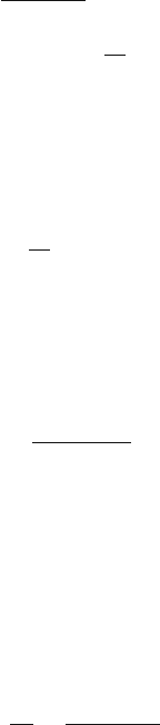
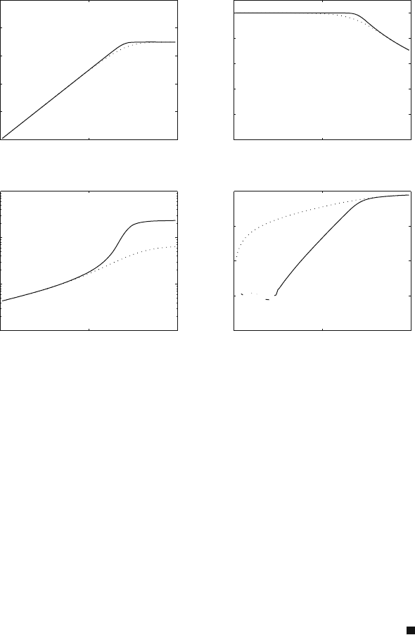
Example 15.2 Plot the output queuing switch performance for switches; one has
B
1
= 16 and B
2
= 64 and the other has B
1
= 4 and B
2
= 16. Assume the SF is an
ADMN network with packet acceptance probability p
a
= 0.7.
For an ADMN network, m = 3. Figure 15.6 shows the switch throughput,
efficiency, and loss probability for the switch with two input queue sizes. The solid
line is for a switch with B
1
= 16 and B
2
= 64. The dotted line is for a switch with
B
1
= 4 and B
2
= 16.
We note that the switch throughput saturates at a maximum value Th = p
a
as
soon as a approaches p
a
. This trend is the same irrespective of the buffer size.
568 15 Switch Modeling
0 0.5 1
0
0.2
0.4
0.6
0.8
1
Input traffic
Throughput
0 0.5 1
0
0.2
0.4
0.6
0.8
1
Input traffic
Efficiency
0 0.5 1
10
−1
10
0
10
1
10
2
Input traffic
Delay
0 0.5 1
10
−20
10
−15
10
−10
10
−5
10
0
Input traffic
Loss probability
Fig. 15.6 Performance of an output queuing switch versus the input traffic. Switch throughput,
efficiency, delay, and loss probability are plotted against input traffic. The solid line is for a switch
with B
1
= 16 and B
2
= 64. The dotted line is for a switch with B
1
= 4andB
2
= 16. An ADMN
network is assumed with p
a
= 0.7
The switch efficiency is 100% for most of the input traffic as long as a ≤ p
a
.
When the input traffic is a ≈ p
a
, the efficiency of both switches decreases at ap-
proximately the same rate. However, the efficiency of the switch with smaller input
and output queues starts its decrease slightly before a approaches p
a
.
The delay of both switches increases with increased input traffic since the input
queues start to fill up. As soon as the arrival probability approaches the SF accep-
tance probability (a ≈ p
a
), we see that the delay of both switches saturates at its
maximum value. The switch with larger buffers shows higher delay as shown.
The switch with smaller input and output queues shows higher packet loss prob-
ability even for very small values of a. As soon as a ≈ p
a
, both switches give very
high and equal cell loss probabilities.
Although the previous example was crude and employed several simplifications,
we can make one very important conclusion. The throughput of the input queu-
ing switch is limited by the performance of the switch fabric it is using. The best
throughput we can hope to achieve is given by
Th(max) ≤ p
a
(15.83)
15.4 Shared Buffer Switch 569
And the packet loss probability is given from the conservation of flow by
L = 1 −Th = 1 − p
a
(15.84)
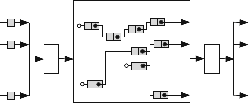
15.4 Shared Buffer Switch
Figure 15.7 shows a shared buffer switch. In a shared buffer switch, there is one
common memory that is accessed by all input and output ports. The memory is
organized, using linked lists, into several FIFO queues such that each output port
has associated with it at least one queue. At the beginning of each time step, packets
arrive at the inputs and are temporarily stored in a small buffer at each input port
until the shared memory controller services them. The shared memory controller
scans each input port in turn and appends incoming packets to the correct FIFO
queue associated with each output port.
We make the following assumptions to simplify our analysis:
1. The shared buffer is divided into N linked lists (or queues) such that each linked
list is associated with an output port.
2. The maximum size of each linked list is B and the total size of the shared memory
is NB.
3. Each queue has N inputs and one output.
4. a is the packet arrival probability at any input of the switch.
5. Packet departure probability from any queue is 1.
6. Packets could be served in the same time step at which they arrive.
7. Each arriving packet has equal probability 1/N of being appended at the end of
any linked list associated with an output port.
8. Data broadcast or multicast are not implemented.
9. Packets will be lost when more than one packet are destined to an output port
whose linked list is full.
N
1
Shared Buffer
Write
Controller
2
N
1
2
Inputs
Outputs
Read
Controller
N
1
2
Fig. 15.7 The shared buffer switch
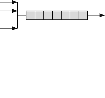
570 15 Switch Modeling
Fig. 15.8 The arrival and
departure probabilities for
one linked list associated
with an output port. The
arrival and departure
probabilities are shown
c = 1
Output lin
k
Queue size = B
...
x = a/N
1
2
N
Figure 15.8 shows one linked list associated with an output port. The arrival and
departure probabilities are shown.
Under these assumptions, we can model the shared buffer as a collection of inde-
pendent M
N
/M/1/B queues. We study one linked list belonging to an output port.
We call this the tagged output port. The probability that an input port has a packet
destined to the tagged output is
x =
a
N
(15.85)
The probability that the tagged output port receives i packets in one time slot is
given by
r
i
=
N
i
x
i
(1 − x)
N−i
(15.86)
where 0 ≤ i ≤ N.
According to our assumptions, the departure probability from the linked list is
c = 1 (15.87)
Having found the arrival and departure probabilities, we are now able to write
down the state transition matrix for the tagged linked list. This is a lower Hessenberg
matrix of dimension
(
B +1
)
×
(
B +1
)
with B subdiagonals.
For the special case when B = 6, P is given by
P =
⎡
⎢
⎢
⎢
⎢
⎢
⎢
⎢
⎢
⎣
r
0
+r
1
r
0
00000
r
2
r
1
r
0
0000
r
3
r
2
r
1
r
0
000
r
4
r
3
r
2
r
1
r
0
00
r
5
r
4
r
3
r
2
r
1
r
0
0
r
6
r
5
r
4
r
3
r
2
r
1
r
0
0 p
5
p
4
p
3
p
2
p
1
p
0
⎤
⎥
⎥
⎥
⎥
⎥
⎥
⎥
⎥
⎦
(15.88)
where the terms p
i
at the bottom row are given by
p
i
= 1 −
i
j=0
r
j
(15.89)

15.4 Shared Buffer Switch 571
This ensures that that the sum of each column of the transition matrix is unity.
For example, p
2
is given by
p
2
= 1 −
(
r
0
+r
1
+r
2
)
(15.90)
The solution to the state vector is simply found by assuming a value for s
0
and
then using forward substitution to find all the other components. The normalizing
condition is invoked to obtain the true value for the state vector. Once the state
vector is determined using numerical techniques, the switch performance can be
calculated.
Shared buffer performance
The throughput of the tagged output Th is given by
Th = (1 −s
0
) +s
0
(1 −r
0
) (15.91)
where s
0
is the probability that the linked list is empty. The first term on the RHS is
the probability that a packet leaves the queue given that the queue is not empty. In
that case, the statistics of packet arrival do not matter. The second term on the RHS
is the probability that a packet leaves the queue, given that it was empty and one or
more packets arrived at the queue input. Simplifying, we get
Th = 1 −s
0
r
0
packets/time step (15.92)
To find the efficiency of the shared buffer switch, we must first find the traffic
arriving at the tagged linked list. The average number of packets arriving at the
tagged output is given by
N
a
(in) =
N
i=0
ir
i
= xN
= a packets/time step (15.93)
The efficiency of the input queuing switch is defined as the ratio between output
traffic and input traffic:
η =
N
a
(out)
N
a
(in)
=
1 −s
0
r
0
a
(15.94)
According to our assumptions, packets are lost in a shared buffer switch if more
than one packet arrive when the tagged linked list is starting to fill. To find the lost