Gebali F. Analysis Of Computer And Communication Networks
Подождите немного. Документ загружается.

14.10 Augmented Data Manipulator Network (ADMN) 531
Table 14.3 SE settings for path in ADMN network from input 6 to output 1 based on decimal
value of routing vector
r
0
= (r
0
± N)modN
Stage i = 0 i = 1 i = 2 i = 3
δ
i
= 2
n−i−1
421NA
μ
i
0 −1 −1NA
Input routing vector (
r
i
)3310
Output routing vector (
r
i+1
)3100
Entry row location of packet (R
i
)6 6 0 1
Exit row location of packet (R
i+1
)6 8≡ 01 1
For our case, the new routing vector will be
r
0
= (−5 +8) mod 8 = 3 (14.62)
Let us illustrate this routing algorithm by finding how a path is established be-
tween input at row 6 and output at row 1 when
r
0
= 3. The routing decisions at each
stage are explained in Table 14.3.
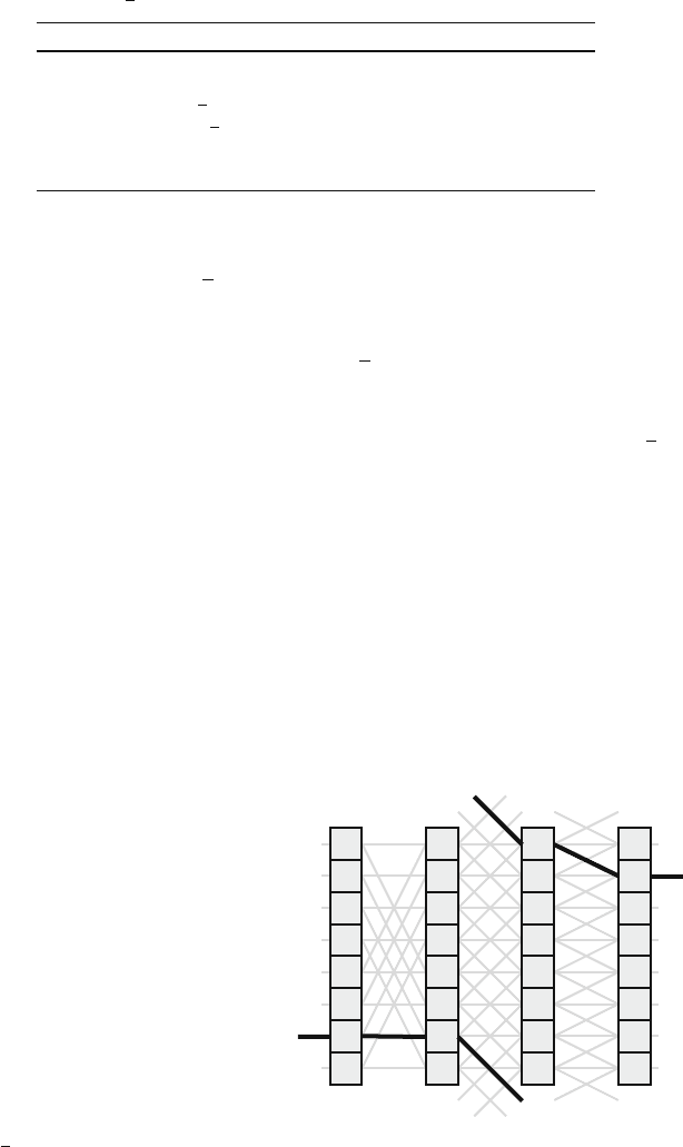
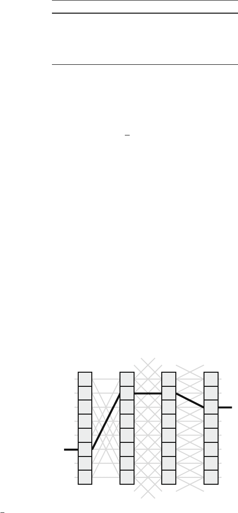
Figure 14.15 shows the path chosen to route a packet from input at row 6 to
output at row 1 based on modulo operation on decimal value of routing vector
r
0
.
The maximum shift that a packet experiences using this network is ±(N − 1).
This implies that there is only one possible route when R = D. This problem could
be solved by introducing double links for the straight connection and changing our
SEs to 4 ×4 switches instead of 3 ×3 ones.
14.10.3 Second ADMN Routing Algorithm
The first routing algorithms discussed in the previous section required addition and
subtraction operations—and these operations were repeated at each stage. Needless
Fig. 14.15 Path chosen in the
ADMN network to route a
packet from input at row 6 to
output at row 1 based on
modulo operation on routing
vector
r
0
= 3
0 1 2 3Stage:
Inputs
Outputs
0
1
2
4
3
5
6
7
0
1
2
4
3
5
6
7
0
1
2
4
3
5
6
7
0
1
2
4
3
5
6
7
a
b
d
c
f
e
a
b
d
c
f
e

532 14 Interconnection Networks
Table 14.4 SE settings for
path establishment in ADMN
network based on 2’s
complement number format
Sign bit value Bit value Connection type
0 0 Straight
01Up
1 0 Straight
1 1 Down
to say, these operations are complex and slow compared to the operations required
of the second routing algorithm discussed here. This routing algorithm is also dis-
tributed among the SEs and relies on 2’s complement representation of the routing
vector. Calculating the routing vector is done only once at the input stage. The rest
of the stages merely scan the bits of the routing vector to make up their routing
decisions.
To establish a path from a source address at an input port location S to a destina-
tion address at an output port location D, we calculate r as
r = D − S (14.63)
where r is represented in
(
n + 1
)
-bit 2’s complement notation.
A switching element at stage i will have to scan two bits of the routing vector:
the sign bit (which is bit n) and bit n −i − 1. Therefore, an SE at stage 0 scans the
sign bit and bit n − 1. An SE at stage 1 scans the sign bit and bit n − 2, and so on.
Finally, an SE at stage n − 1 scans the sign bit and bit 0. The SE settings for path
establishment are based on the rules explained in Table 14.4.
As an example, assume S = 7 and D = 2. In that case, r is given as
r = D − S =−5 (14.64)
The routing vector in n +1-bit 2’s complement notation will be
r =
1011
(14.65)
The path selected is explained in Table 14.5, and Fig. 14.16 shows the path cho-
sen to route a packet from input at row 7 to output at row 2 based on 2’s complement
representation of routing vector r.
Table 14.5 SE settings for path in ADMN network from input S = 7 to output D = 2 based on
the 2’s complement representation of the routing vector r. The sign bit for routing vector is r
n
= 1
Stage i = 0 i = 1 i = 2 i = 3
Bit scanned r
2
= 0 r
1
= 1 r
0
= 1NA
SE connection Straight Down Down NA
Row location (R
i
)7 7 1 2
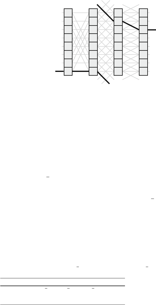
14.10 Augmented Data Manipulator Network (ADMN) 533
Fig. 14.16 Path chosen in the
ADMN network to route a
packet from input at row 7 to
output at row 2 based on 2’s
complement representation of
routing vector
0 1 2 3
Stage:
Inputs
Outputs
0
1
2
4
3
5
6
7
0
1
2
4
3
5
6
7
0
1
2
4
3
5
6
7
0
1
2
4
3
5
6
7
a
b
d
c
f
e
a
b
d
c
f
e
Finding the Alternative Route
To find an alternative route for the incoming packet, we calculate the routing vector,
as in the previous section, then we find the 2’s complement of the routing vector.
For our case, the original routing vector is
r =
1011
(14.66)
The 2’s complement of this vector is
r =
0101
(14.67)
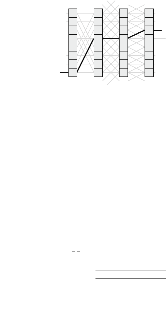
The path selected is explained in Table 14.6, and Fig. 14.17 shows the path chosen
to route a packet from input at row 7 to output at row 2 based on routing vector
r.
14.10.4 Third ADMN Routing Algorithm
The third ADMN routing algorithm is also distributed among the SEs and relies on
combining RSD with modulo operation. Calculating the routing vector is done only
Table 14.6 SE settings for path in ADMN network from input S = 7 to output D = 2 based on
the 2’s complement representation of the routing vector
r. The sign bit for routing vector is r
n
= 0
Stage i = 0 i = 1 i = 2 i = 3
Bit scanned r
2
= 1 r
1
= 0 r
0
= 1NA
SE connection Up Straight Up NA
Row location (R
i
)7 3 3 2
534 14 Interconnection Networks
Fig. 14.17 Path chosen in the
ADMN network to route a
packet from input at row 7 to
output at row 2 based on
routing vector
r
0 1 2 3Stage:
Inputs
Outputs
a
b
d
c
f
e
a
b
d
c
f
e
0
1
2
4
3
5
6
7
0
1
2
4
3
5
6
7
0
1
2
4
3
5
6
7
0
1
2
4
3
5
6
7
once at the input stage. The rest of the stages merely scan the bits of the routing
vector to make up their routing decisions.
To establish a path from a source address at an input port location S to a destina-
tion address at an output port location D, we need to calculate the routing vector r
as given by the formula
r = D − S (14.68)
where r is now represented in an n-bit RSD notation. The bits of the resulting RSD
number are examined starting with the MSB first. So bit n−1 is examined by SEs at
stage 0. Bit n −2 is examined by SEs at stage 1, and so on. Finally, bit 0 is examined
by SEs at stage n −1. The SE settings for path establishment are based on the rules
explained in Table 14.7.
As an example, assume S = 5 and D = 2. In that case r is given as
r = D − S =−3 (14.69)
The routing vector in n-bit RSD notation will be
r =
0
1 1
(14.70)
Table 14.7 SE settings for
path establishment in ADMN
network based on RSD
number format
Bit value Connection type
1Up
0 Straight
1Down
14.10 Augmented Data Manipulator Network (ADMN) 535
Table 14.8 SE alternative
settings for path in ADMN
network from input 5 to
output 2 based on RSD
number format
Stage 0 1 2
Bit scanned r
2
r
1
r
0
Bit value 0 1 1
Connection type Straight Up Up
The path selected is explained in Table 14.8.
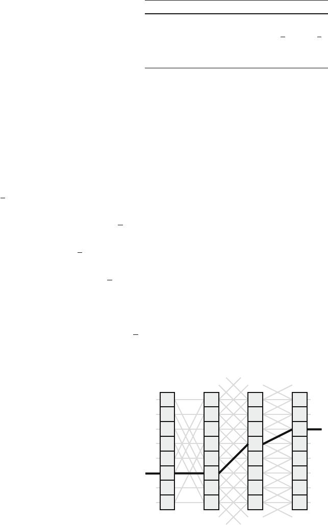
Figure 14.18 shows the path chosen to route a packet from input at row 5 to
output at row 2 based on RSD number format of the routing vector r.
Finding the Alternative Route
The alternative route using the RSD number format is obtained by finding the value
of
r according to the formula
r =
(
r ± N
)
mod N (14.71)
The alternate path
r is
r = (−3 +8) mod 8 = 5 (14.72)
which corresponds to the routing vector
r =
101
(14.73)
Fig. 14.18 Path chosen in the
ADMN network to route a
packet from input at row 5 to
output at row 2 based on RSD
number format of the routing
vector r
0 1 2 3Stage:
Inputs
Outputs
0
1
2
4
3
5
6
7
0
1
2
4
3
5
6
7
0
1
2
4
3
5
6
7
0
1
2
4
3
5
6
7
a
b
d
c
f
e
a
b
d
c
f
e
536 14 Interconnection Networks
Table 14.9 SE alternative
settings for path in ADMN
network from input 5 to
output 2 based on RSD
number format
Stage i = 0 i = 1 i = 2
Bit scanned r
2
r
1
r
0
Bit value 1 0 1
Connection type Down Straight Down
The path selected is explained in Table 14.9. Note that each stage scans one bit
in descending order.
Figure 14.19 shows the path chosen to route a packet from input at row 5 to
output at row 2 based on RSD value of routing vector
r.
The maximum shift that a packet experiences using this network is ±(N − 1).
This implies that there is only one possible route when R = D. This problem could
be solved by introducing double links for the straight connection and changing our
SEs to 4 ×4 switches instead of 3 ×3 ones.
14.10.5 Analysis of ADMN Network
An N × N ADMN network is built using 1-to-3 selectors in the input stage (i = 0),
3 × 3 crossbar SEs in n − 1 internal stages (0 < i < n), and 3-to-1 concentrators
in the output stage (i = n). Therefore, we can use the results we obtained for the
banyan network after some modifications.
Because we have 1-to-3 selectors at stage 0, the packet arrival and departure
probabilities at each selector are given by
Fig. 14.19 Path chosen in the
ADMN network to route a
packet from input at row 5 to
output at row 2 based on RSD
number format for the
alternative routing vector
r
0 1 2 3
Stage:
Inputs
Outputs
0
1
2
4
3
5
6
7
0
1
2
4
3
5
6
7
0
1
2
4
3
5
6
7
0
1
2
4
3
5
6
7
a
b
d
c
f
e
a
b
d
c
f
e

14.10 Augmented Data Manipulator Network (ADMN) 537
a
0
(in) = a (14.74)
a
0
(out) =
a
3
(14.75)
For the SEs at the internal stages (0 < i < n), we use the expression for the
throughput in (14.5) with N = 3
a
i
(in) = a
i−1
(out) (14.76)
a
i
(out) = 1 −
1 −
a
i
(in)
3
3
(14.77)
At the output stage (i = n), we have 3-to-1 concentrators. For an ADMN network
whose output concentrator accepts m packets (1 ≤ m ≤ 3), we can write the arrival
and departure probabilities at the output as
a
n
(in) = a
n−1
(out) (14.78)
a
n
(out) =
m−1
j=1
jx
j
+m
3
j=m
x
j
(14.79)
where 1 ≤ m ≤ 3 is the maximum number of packets that could be accepted at the
output in one time step and x
j
is the probability that j packets arrived
x
j
=
3
j
a
j
n
(in)
[
1 −a
n
(in)
]
3−j
(14.80)
According to (14.3), we can write the traffic at the input of the ADMN network
as
N
a
(in) = a (14.81)
and the output traffic at the tagged output of the network is
N
a
(out) = a
n
(out) (14.82)
where a
n
(out) is given by (14.79).
The throughput of the ADMN network is given by
Th = N
a
(out) = a
n
(out) (14.83)
The packet acceptance probability for the ADMN network is given by
p
a
=
Th
N
a
(in)
(14.84)
538 14 Interconnection Networks
The delay of the ADMN network is defined as the average number of attempts
to access the desired output. The probability that the packet succeeds after k tries is
given by the geometric distribution
p(k) = p
a
(
1 − p
a
)
k
(14.85)
The average delay time is
n
a
=
∞
k=0
kp(k)
=
∞
k=0
kp
a
(
1 − p
a
)
k
=
1 − p
a
p
a
(14.86)
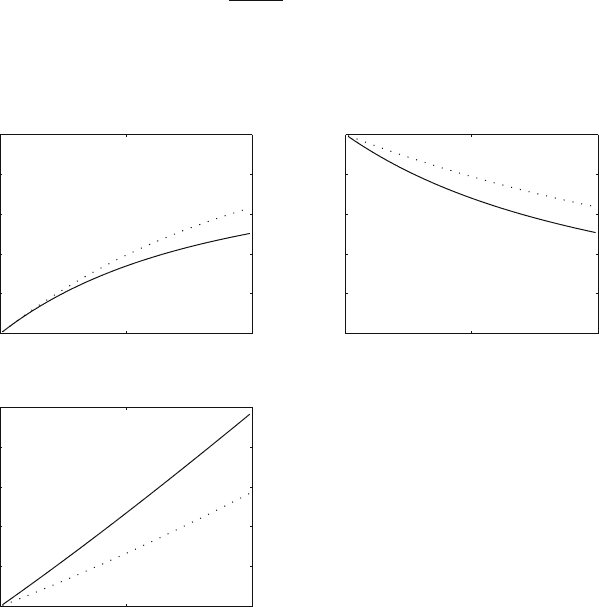
Example 14.4 Plot the throughput (Th), the access probability ( p
a
), and the aver-
age delay (n
a
) for the ADMN network versus the input traffic when the size of
0 0.5 1
0
0.2
0.4
0.6
0.8
1
Input traffic
Throughput
0 0.5 1
0
0.2
0.4
0.6
0.8
1
Input traffic
Acceptance probability
0 0.5 1
0
0.2
0.4
0.6
0.8
1
Input traffic
Delay
Fig. 14.20 Variation of the throughput, the packet acceptance probability, and the delay with the
input traffic when N = 64 for the ADMN network (solid line) and the similar-sized crossbar
network (dotted line). The output concentrator accepts only one packet
14.11 Improved Logical Neighborhood (ILN) 539
the network is N = 64 and compare this with the similar-sized crossbar network.
Assume an output concentrator that accepts only one packet.
We evaluate the expressions for throughput, packet acceptance probability, and
delay when N = 64 and a is varied for both the ADMN network and the cross-
bar network. Figure 14.20 shows the variation of throughput, the packet acceptance
probability, and the delay with the input traffic when N = 64 for the ADMN net-
work (solid line) and the crossbar network (dotted line). We see that the crossbar
network shows superior performance for the same number of input and output ports
as expected.
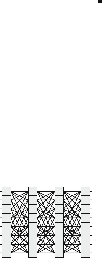
14.11 Improved Logical Neighborhood (ILN)
This family of networks is based on the data manipulator network but has much
better fault tolerance capability [22]. Figure 14.21 shows an 8 ×8 ILN network. For
an N × N network, the number of stages is n + 1 where n = lg N, and the number
of SEs in each stage is N. Each SE is an (n + 1) ×(n + 1) crossbar switch and the
number of links between the stages is (n + 1)N.
An N × N ILN network is built using 1-to-(n + 1) selectors in the input
stage (i = 0) and all internal stages (0 < i < n) have identical SEs that are
(n + 1) × (n + 1) crossbar switches. The output stage (i = n) has (n + 1)-to-1
concentrators.
The ILN network provides n! alternate paths between any input and any out-
put. For the 8 × 8 case, we have six alternate paths. As such, the network is
very fault tolerant and the blocking probability is much smaller than other MIN
networks.
SE(i, j) is connected to SE(i + 1, k) such that k is given by
Fig. 14.21 An improved
logical neighborhood
network (ILN) for N = 8and
n = lg 8 = 3
01 2 3Stage:
Inputs
Outputs
0
1
2
4
3
5
6
7
0
1
2
4
3
5
6
7
0
1
2
4
3
5
6
7
0
1
2
4
3
5
6
7
540 14 Interconnection Networks
k =
⎧
⎪
⎪
⎪
⎪
⎪
⎪
⎪
⎪
⎨
⎪
⎪
⎪
⎪
⎪
⎪
⎪
⎪
⎩
j straight connection
C
0
(
j
)
0-cube connection
C
1
(
j
)
1-cube connection
C
2
(
j
)
2-cube connection
(14.87)
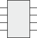
where 0 ≤ i < n. Figure 14.22 shows the four outputs of the switch and the opera-
tions they do on incoming packets.
14.11.1 Routing Algorithm for ILN Network
We discuss here one distributed routing algorithm that does not involve arithmetic
operations and relies only on bitwise XOR operations involving the source address
S and the destination address D. This leads to very fast routing decisions at each SE
and is very compatible with high-performance switches.
The routing vector r is given by
r = XOR
(
S, D
)
(14.88)
where the routing vector r carries the information about the desired path. The path
selected corrects the routing vector r such that all its bits are zeros to indicate that
the packet has reached the destination row address.
Each SE is able to correct a “1” bit located at any position in r. In addition, any
SE is also able to destroy an already-existing “0” in r by changing it to a “1”. This
action might be necessary in order to select an alternative route in case of contention.
The reason for this strategy will be explained in the next section.
Table 14.10 shows the outputs that should be used to establish the path based on
the numerical value of r. The number of bits that need correction by proper selection
of the output ports varies between 0 and 3. For example, if the input address were
010 and the destination address were 010, then the routing vector is r = 000 and
the straight connection should be chosen through all stages. On the other hand, if
the source address were 010 and the destination address were 101, then the routing
Fig. 14.22 Each output of an
ILN switching element
SE(i, j) performs a different
function on j
S (straight) connection
C
0
connection
C
1
connection
C
2
connection
SE(i,j)
0
1
3
2
Inputs