FTA (изд-во). Flexography: Principles And Practices. Vol.1-6
Подождите немного. Документ загружается.


66 FLEXOGRAPHY: PRINCIPLES AND PRACTICES
T
he following section will outline
the minimum mechanical re-
quirements needed to achieve
satisfactory results from mount-
ing and proofing equipment.
Machinery used for mounting
and proofing halftone process color work
requires the smallest mechanical tolerances
achievable.
EQUIPMENT CALIBRATION
The following inspection checks and cor-
rective adjustments should be carried out in
the order listed to ensure proper mechanical
function.
Leveling the Machine
Accurate leveling avoids proofing prob-
lems. The machine must be level along the
plate cylinder pedestal-support beam and
transversely across the side frames. An out-
of-level machine will have a twist, causing the
plate cylinder to be out of parallel with the
impression cylinder. As a result, the optical
mirrors will show error from left to right and
the reference straightedge will not be true.
To level the equipment correctly, all for-
eign matter, dust and dirt must be cleaned
from the machine. For side-to-side leveling,
a properly calibrated and adjusted machin-
ist’s level should be placed on the top of the
impression cylinder and square with the
scribe line. For front-to-back leveling, the
level should be placed on each of the end
support frame (in many models, the level is
built into these frames). The adjustable feet
are raised or lowered as necessary. On older
models, it is important to specifically check
the level of the plate cylinder compared to
the impression cylinder.
Impression Cylinder Concentricity
The impression cylinder usually cannot be
adjusted within the end-support frames
which hold it, and becomes the object
against which all other parts must be judged.
The impression cylinder must be as nearly
perfect in concentricity and surface condi-
tion as possible with zero taper.
Once the impression cylinder is absolutely
level, it should be checked using a dial indi-
cator. A dial indicator, capable of showing
deviations of 0.0001", mounted on a magnet-
ic base, should be used to take concentricity
readings in the middle and about 5" from
each end of the cylinder.
Total concentricity run-out should not
exceed 0.0005". If the excess run-out is con-
stant, it may be possible to rotate or change
impression-cylinder bearings to improve the
condition.
Using an outside diameter micrometer, the
cylinder is measured for taper, with readings
taken every few inches along the cylinder
length. Deviations should not exceed
0.0005".
Condition of Plate Cylinders
Plate-cylinder walls must be clean and free
of foreign matter, including ink and grease.
They should also be free of cuts, nicks, dents
Preparing for
Mounting and Proofing

or other surface damage. Plate-cylinder jour-
nals, as well, must be clean and free of sur-
face damage. Check the concentricity of the
plate cylinder using a dial indicator. The
total indicated run-out (TIR) should not
exceed 0.001" for line work and 0.0005" for
process work. Surface nicks and scratches
can be buffed out with fine 400- to 600-grit
emery paper.
Note: Each time a plate cylinder is used
it should be checked for concentricity with
a dial indicator before mounting. Damage
which affects cylinder concentricity could
have occurred since its last use.
Check the plate-cylinder diameter and
taper following the same procedure as
above for checking taper of the impression
cylinder. Deviation should not exceed 0.001"
across the entire face of the cylinder.
Normally, the diameter and taper check
need only be made as new cylinders are
received or as used ones are re-machined or
resized to correct surface damage.
When a sleeve-cylinder system is used, the
concentricity of the sleeve, the shaft and the
complete assembly must be checked very
closely. Each assembly and subsequent
change of assembly can affect final concen-
tricity of the plate-mounting surface.
Plate-Cylinder-to-
Impression-Cylinder Relationship
The mechanical relationship between the
impression cylinder and the plate cylinder
must be such that repeated proofs under the
same settings will yield the same results.
This requires the elimination of lost motion
by adjusting screws, plate cylinder and bear-
ings, as well as any devices that hold the
plate cylinders and the impression cylinder
in position. Older equipment can develop
excess wear and warrants being inspected
for possible refurbishment.
The plate-cylinder journals and bearing
supports, or pedestals, must always be par-
allel to the impression cylinder. Parallelism
is essential to detecting nonuniform areas in
the plates, such as low spots or nonprinting
areas, during proofing.
A suitable method of testing parallelism on
adjustable-plate cylinder models uses a
mechanically correct plate cylinder, set in
the normal proofing position, without a gear
attached. The eccentric journal bearings on
the plate cylinder pedestal are turned to the
neutral position, ensuring the cylinder sup-
port pedestals are firmly locked into posi-
tion and allowing no fore-and-aft play. Three
2"-wide strips of cellophane are inserted
between the printing and impression cylin-
ders, one strip at each end and one at the
center. The impression cylinder is brought
into contact with the printing cylinder. If
plate-cylinder pedestals are motor activated,
the plate and impression cylinders should be
brought into contact cautiously and slowly
to avoid damage.
Under these conditions, each cellophane
strip should pull out with the same amount
of resistance. If not, the equipment must be
corrected mechanically until satisfactory
parallelism is achieved.
The verticality and/or height of the plate-
cylinder support pedestals may be the cause
of unsatisfactory parallelism. In some rare
instances, they may require shimming or re-
machining. If this is the case, contact the
equipment manufacturer for recommenda-
tions on remedial action.
For fixed-plate cylinder support models
with adjustable impression cylinders, the test
can be conducted in a similar same way, as
long as the impression cylinder is in a neu-
trally “square and parallel” position.
Condition of Gears
Make sure the gears are clean and free of
damage or missing teeth. The plate-cylinder
gear must fit the cylinder journal snugly with
no more than 0.002" total tolerance. The gear
must not be misaligned or “cocked” when
the securing set screw is tightened. It is rec-
MOUNTING AND PROOFING 67

68 FLEXOGRAPHY: PRINCIPLES AND PRACTICES
ommended that a gear be purchased for
each cylinder repeat and only used for
mounting. This will help to eliminate anoth-
er variable in the process.
CARE OF EQUIPMENT
The mounting equipment, impression sur-
faces, plate cylinders and gears are precision
tools and must be handled with care and
protected from abuse. It is essential that all
equipment used for mounting process work
is kept as clean as possible in order to main-
tain sharp, accurate proofs.
Daily attention should be paid to the fol-
lowing instructions:
• Keep all surfaces clean.
• Make sure the plate and proofing cylin-
der surfaces are free of any surface
damage, including knife cuts. The dis-
placed metal makes it more difficult to
take sharp, accurate proofs. If an
impression surface is damaged, contact
the equipment manufacturer for recom-
mendation of corrective action.
• Lubricate all metal parts that mate and
move. Apply a light film of oil to all
unpainted portions of the machine to
prevent rust and corrosion.
• Carefully handle and clean mirrors.
Note: The semitransparent mirror
coating can be destroyed by oily fin-
gerprints and by improper cleaning.
Do not use solvents that may dissolve
the coating. Use only a soft, lint-free
cloth lightly dampened with a mild
soap and water solution or any pre-
pared glass cleaner. Caution should be
taken to avoid getting moisture
between the optical bar and mirrors.
Rust may develop and effect mirror
accuracy. If rust is present, it must be
removed.
• Every few months, or more frequently,
depending on the average hours of
machine operation per day, add one or
two charges of standard machine
grease into the machine’s grease fit-
tings. Clean the fittings with a cloth, and
remove all foreign matter before apply-
ing the grease.
• Make it a good practice to periodically
wash the machine and remove all old oil,
grease, ink and other substances. Any
solvent that will cut the oil, grease, ink
and foreign matter may be used, but take
care to keep the solvents from coming
into contact with the mirror viewer on
the optical mounting and proofing unit.
• Check all electrical connections and
wires. The frequency of these checks will
depend on how often the machine is used.
UNDERSTANDING THE
MOUNTING INSTRUCTIONS
A great deal of planning has gone into any
job before it reaches the mounting and
proofing department. It is necessary for the
mounting operator to understand each step,
and make certain everything is ready before
mounting plates (Table 15). The production
order must be studied carefully to ensure
that the following are correct:
• The plate-cylinder repeat size is the
same as the design repeat size or multi-
ples of it.
• The reading direction of the plates (ver-
tical, horizontal, right side up, upside
down, etc.) is specified in relation to the
web at the rewind. The “rewind figure”
shows the possible copy positions on a
given web.
• The gear-pitch diameter is the same as
the plate-cylinder diameter with mount-
ed plates in place.
• The positioning of the plates across and
around the plate cylinder, i.e., the loca-
tion, size and color of the eye spots,
guidelines and register marks are cor-
rect.
• The side of the substrate to be printed,

either surface printing or reverse printing
(i.e., printing on the underside reversed
for proper reading through the film) is
stated.
• The number of colors, color sequence
and the key color to determine which
set of plates all others will register to,
and therefore, the first set of plates to
be mounted is identified. The same
applies to the sets of plates to be mount-
ed second, third, etc.
• A study made of the layout, digital
proof, color sketch, printed sample,
blueprint, die-line layout or finished art-
work to determine the positioning of
plates as to bag, over-wrap or other
package, sealing, trimming of stock or
copy bleed.
• Special bag, carton or other package
construction specifications, such as spe-
cial lip, header, bag, double wall, special
seams, folds, slots and special perfora-
tions and opening instructions must be
noted and adhered to.
TOOLS NEEDED
The mounting and proofing department
should have the following tools on hand to
help in professional mounting. Of course,
some tools are more essential than others,
and these include but are not limited to:
• smooth-surfaced proofing paper, approx-
imately 0.003" thick ;
• four ink braying rollers;
• sheet of Plexiglas for ink rollout;
• set of proofing inks;
• set of Allen wrenches,;
• feeler gauges;
• dial indicator and magnetic base;
• steel rule;
• ball-point pen;
• makeready tape of various thickness;
• cleaning rags;
• magnifying glass; and
• razor blade knives.
A more comprehensive list of tools
appears in Appendix A.
MOUNTING AND PROOFING 69
Table 15
■ Plate-cylinder repeat size
■ Reading direction of the plates in relation to
the web at the rewind.
■ Gear-pitch diameter.
■ Positioning of the plates across and around
the plate cylinder.
■ Side of the substrate to be printed
■ Number of colors, color sequence and the
key color
■ Plate position as to bag over-wrap or other
package, sealing, trimming of stock or copy
bleed
■ Special construction specifications, special
perforations and opening instructions
PRODUCTION ORDER CHECKLIST
PRIOR TO PLATE MOUNTING

70 FLEXOGRAPHY: PRINCIPLES AND PRACTICES
W
ith clean, level, mechan-
ically true mounting and
proofing equipment that
is in good repair, the
specific mounting in-
structions of the job
understood and the necessary tools on hand,
the operator should be ready to begin plate
mounting.
Mounting and proofing a critical process
job is very similar to a critical line job.
Helpful hints for accomplishing the process
job will be found in appropriate steps
throughout this dissertation on line work.
PLATE-MOUNTING PROCEDURES
1. Assemble all plate cylinders, gears and
bearings necessary for the job and
check each for correct size, mechanical
fit and cleanliness.
2. Position the plate cylinder by measur-
ing the distance between the two plate-
cylinder journal bearings – center to
center. Position the plate-cylinder sup-
port pedestals equidistant from the
plate-cylinder bearings and far enough
to the left to permit the plate-cylinder
gear to align with the gear on the
impression cylinder.
3. Place the plate cylinder on the cylinder
supports. When possible, mount the job
using the same plate-cylinder bearings
to be used in the press. Move the cylin-
der supports inward to allow the small
cylinder-support bearings to touch the
plate-cylinder walls on each end. The
entire assembly must allow the plate-
cylinder gear and impression-cylinder
gears to align. Lock the supports firmly
into position. Avoid too much forward
pressure as this will reduce the advan-
tage of the anti-backlash gears of the
mounting equipment.
4. When the final position of the plate
cylinder is set, lock it in position allow-
ing no free movement – either side-to-
side or up-and-down. The plate-cylinder
gear should now be engaged with the
impression-cylinder gear; check that
the plate-cylinder gear is also locked in
place.
5. Clean the surface of the plate cylinder
again to make sure it is free of oil, ink,
grease and foreign matter.
6. Position the dividing head on the plate-
cylinder journal opposite the gear end
for jobs requiring multiple repeats
around the cylinder
7. Apply proofing paper with the proper
thickness to bring the impression cylin-
der on gear pitch. Most manufacturers
undercut 0.003" for proofing paper.
(Consult the manufacturer for the cor-
rect thickness.) The paper should be
white with a machine glaze (MG) or
machine finish (MF) as minimum
smoothness. The surface of bleached
kraft is generally too rough and irregu-
lar in caliper to disclose plate variation
for high quality plate makeready. An
extremely clean and unmarred surface
Mounting and Proofing
a Complete Line Job
on the impression cylinder is important
to professional proofing.
8. The sheet of proofing paper should be
precut to size. Knife cuts and proofing-
paper trimming must not be done on the
impression cylinder.
9. Apply proofing paper to the impression
cylinder with masking tape, aligning the
edge of the paper with the scribe line on
the impression cylinder. The paper
should be pulled tight and securely
taped to the impression cylinder in sev-
eral places to eliminate the possibility
of movement or buckling.
10. Draw a complete plate layout on an opti-
cal or mechanical mounting machine to
ensure an accurate, press-ready job.
Take time to mark all the information
given on the job order or printing
instructions. This is also another way to
check plate layouts, avoiding possible
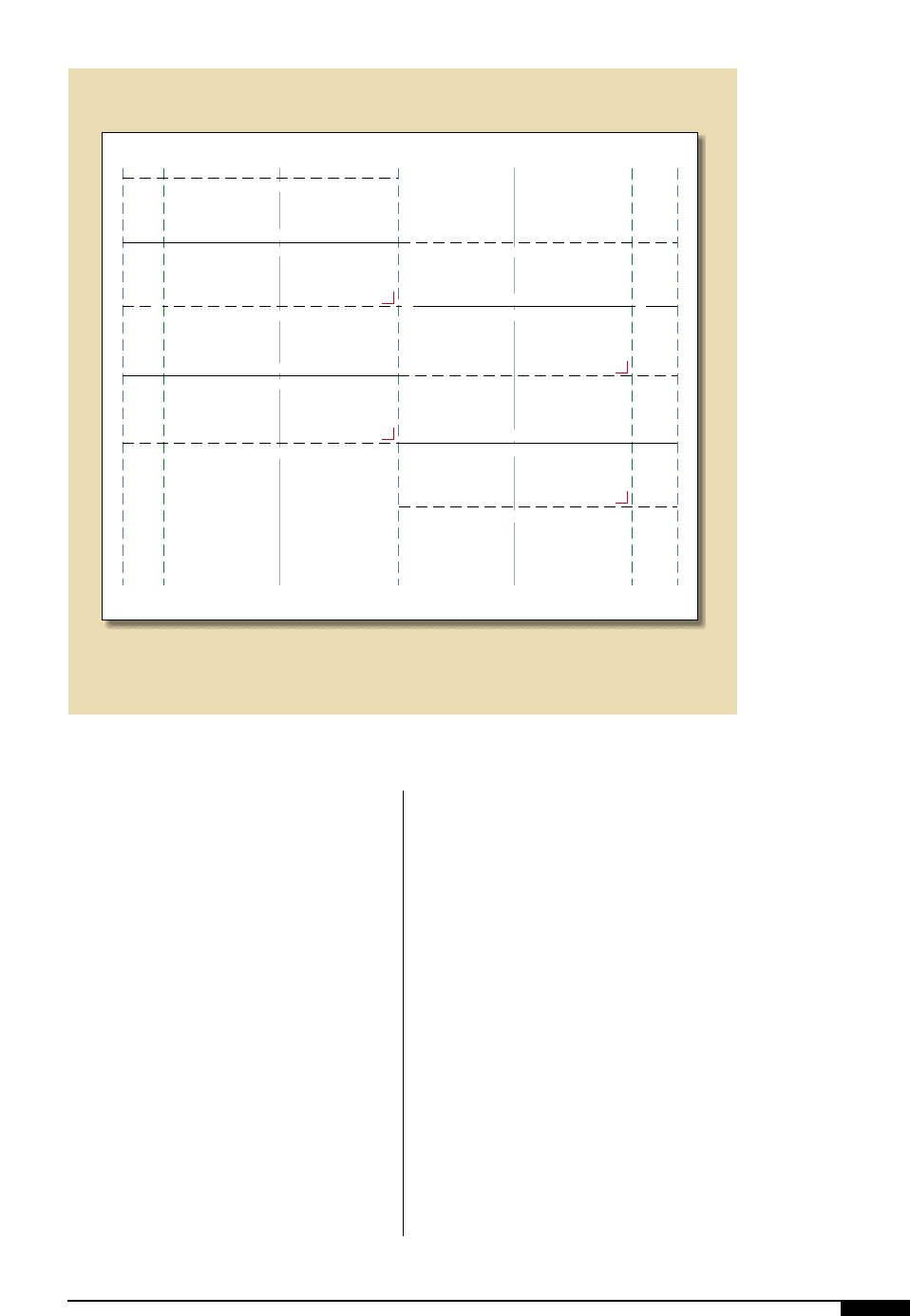
mistakes. Figure
3*
and
3(
, are exam-
ples of layouts, typical of a web press,
properly drawn on a mounting and g
machine using the built-in scriber, tape
and dividing head. An example of a lay-
out for a corrugated box is shown in
Figure
4)
.
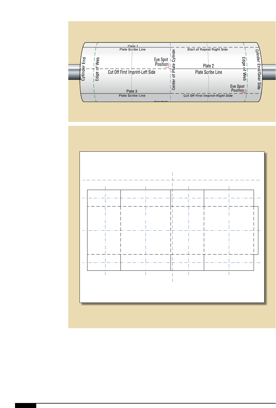
The job shown in Figure
3*
, called for four
design repeats, a minimum of four plates –
two across the cylinder and two around the
cylinder – offset or staggered 180°. The
plate-mounting operator begins the layout
by setting the scribing pen to line up with the
center of the plate cylinder. The scribing pen
MOUNTING AND PROOFING 71
3*
An example pf a
properly drawn layout
on the impression
cylinder. This job calls
for four design repeats.
Start of Repeat Left Side
Cut Off First Imprint-Left Side
Cut Off Second Imprint-End of Repeat
Plate 1
Plate Scribe Line
Plate 3
Plate Scribe Line
Start of Repeat Right Side
Cut Off First Imprint-Right Side
Cut Off Second Imprint-End of Repeat
Plate 2
Plate Scribe Line
Plate 4
Plate Scribe Line
Eye Spot
Position
Eye Spot
Position
Eye Spot
Position
Eye Spot
Position
Edge of Web
Center of Plate Cylinder
Cylinder End
Edge of Web
Cylinder End/Gear Side
3*
72 FLEXOGRAPHY: PRINCIPLES AND PRACTICES
3(
A properly drawn
layout on an impression
cylinder.
4)
A properly drawn layout
for a corrugated box.
All sections of the box
are drawn to exact
dimensions and the lead
edge of the box is pos-
tioned at the top.
3(
Lead Edge of Plate Mount
Machine
Center Line
Front Panel
Back Panel
Glue Flap
Bottom
Top
Panel
Center Lines
4)

is jogged up and down to make a broken ver-
tical line that will help to differentiate
between plate centerlines and other lines
drawn to complete the layout.
From the first plate-cylinder centerline
drawn, the operator sets the tape measure
and moves the scriber to the correct mea-
surement to draw the rest of the vertical
lines that form the layout from measure-
ments given on the specification sheet.
These lines include a line to identify the end
of the cylinder, the edge of the web, the plate
scribe lines and the eye-spot position.
Note: To avoid confusion, the only solid
lines are those to which the plates will be
mounted.
The horizontal lines are now drawn to
complete the layout. This is done by using
the dividing head mounted on the journal of
the plate cylinder. No matter what the repeat
of the cylinder, the dividing head will auto-
matically space the horizontal lines on the
layout to preset angular relationships
around the plate cylinder. The first horizon-
tal line represents the start of the printing
repeat (broken line). This is drawn with the
dividing head set at zero.
On this sample job, two plates are spaced
equally around the cylinder and the second
set is staggered. Therefore, the plate-cylin-
der repeat is divided into four intervals, 90°
apart. The plate cylinder is rotated to the
first number four on the dividing head and
the next line is drawn representing plate 1
centerline, left side (solid) and the start of
repeat right side (broken). The cylinder is
rotated to the next number four on the divid-
ing head to draw the last line or cut off the
second imprint end of the repeat. Additional
lines for eye-spot positions are measured
and drawn, and the gear side is marked on
the layout. This completes the layout. The
first plate cylinder is ready for the applica-
tion of stickyback.
Impression Cylinder Layout for
Corrugated Postprint
Drawing the job layout for plate- (die-)
mounting in the corrugated post-print indus-
try involves drawing the layout of the actual
box on paper covering the impression cylin-
der. (Figure
4)
)
It is important to place the lead edge of the
box drawing at the top. All sections of the
box must be drawn with exact dimensions.
On mounting and proofing machines for cor-
rugated post-print, the plates (dies) are
mounted on a plate cylinder that matches the
print repeat of the press, thus eliminating the
stretch compensation factor in the layout.
In some operations, when the box to be
printed will be cut and creased, an acetate
plot of the cutting die, or a full-size digital
color proof of the images, may be simply
aligned and taped to the impression cylinder.
This eliminates the need to draw the layout
by hand, increasing productivity and accura-
cy. It is important to tape the predrawn tem-
plate “squarely” on the cylinder, with the
lead edge of the box at the top and the emul-
sion-side down against the paper to mini-
mize any effect on the cylinder’s diameter.
Cleaning the Plates and Cylinders
The back of photopolymer plates should
be cleaned thoroughly, removing any foreign
matter or particles that, if trapped between
the plate and the mounting tape, would
effect adhesion or caliper. Prepare the plate
cylinders and sleeves in the same fashion.
When cleaning cylinders and plates, it is
important to allow adequate solvent dry-
time before applying the stickyback to the
cylinder or plate. The same holds true for
flexographic adhesives. Isopropyl alcohol
works well on the cylinders or sleeve
because it leaves no residue.
Use of an incompatible cleaning solvent
can lead to plate-lift on press or make plate
removal very difficult. If the composition of
the adhesive is unknown, consult the tape
MOUNTING AND PROOFING 73
74 FLEXOGRAPHY: PRINCIPLES AND PRACTICES
supplier to ensure that the cleaning solvent
is compatible with the cushion adhesive.
Photopolymer plates processed in new
“safe solvents” must be cleaned thoroughly
before being light finished and prior to
mounting on the cushion adhesive. These
wash-out solvents can leave an oily residue
on the back of the photopolymer plate,
which will cause plate-lift on press.
Trimming and Preparing
the Plate Edge
Whether rubber or photopolymer, finished
plates must be trimmed accurately before
mounting. The preferred method is to use a
plate cutter or foot shear. If a knife, however,
is used, the cut should be made from the
polyester backing side of the plate. Edges
must be smooth and free of nicks and burrs.
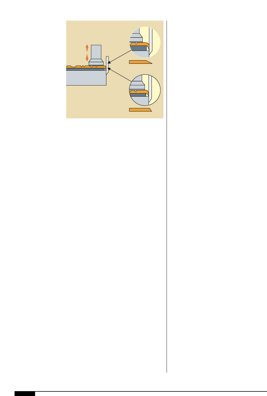
Beveling all sides of the plate is desirable
because it helps keep the plate from lifting
during the pressrun, in addition to providing
a wider area to apply edge sealant. Beveling
may be done by securing a rigid material on
the bed of the plate cutter or foot shear
(Figure
4!
). Place the finished plate on top
of the rigid material and press firmly to trim.
This flexes the edge of the plate allowing a
neatly beveled cut edge. The position and
height of the rigid material determines the
bevel angle.
Applying the Stickyback
Double-sided adhesive film, or stickyback,
is used to secure the plates in position on the
plate cylinder or carrier in either of two
methods. In the first, if the job calls for only
a few small plates – each no longer than one-
fourth the plate-cylinder circumference – the
stickyback may be applied directly to the
plate and then the backed plate may be
applied to the bare cylinder. If compressible
stickyback is used, it should be permitted to
extend beyond the plate about 1" on all sides.
When multiple plates, spread over much of
the cylinder are being mounted, it is expedi-
ent to cover the entire layout area of the
cylinder with the stickyback and then posi-
tion and apply the plates to it.
Stickyback should be applied to the cylin-
der first when mounting individual plates
longer than one quarter of the cylinder cir-
cumference. This will prevent plate buckling
caused by the stickyback bunching when the
plates experience curvature growth at differ-
ent rates. This is especially important in
process work.
The second method is to apply the sticky-
back around the entire cylinder. If using dou-
ble-backed stickyback (protective sheet on
both faces), approximately 6" of backing
along the leading edge should be removed;
then, holding the entire piece with the side
edge as square with the cylinder as possible,
position the leading edge on the cylinder
about 0.5” above the horizontal lead-edge
scribe line. Gradually remove the remainder
of the backing sheet from below the sticky-
back. While rotating the cylinder, smooth
and press the stickyback firmly into position
all around the cylinder. If using single-
backed stickyback (protective sheet on one
face only), use a clean, undamaged piece of
discarded coversheet to prevent premature
adhesion to the plate cylinder.
Using the grooved scribe line in the plate
cylinder as a knife-blade guide, trim the lead-
ing edge of the stickyback straight. Then
4!
Using a modified sheer,
beveling plate edges
creates a wider
surface area to apply
edge sealant and also
prevents the plate from
lifting during a
pressrun.
Plate-Edge Profile
Plate Edge Profile
Feed Board
Hold
Down
Cutting
Knife
4!

press the overlapping trailing end down
firmly over the leading edge groove and trim
the overlap to make a perfect butt joint. The
dividing head, or the impression cylinder
drag brake, can be used to hold the impres-
sion cylinder in position while trimming the
stickyback. At this point the protective
cover should still be on the top side of the
stickyback.
Stickyback and plate-trimmng devices are
available which attach to the mounter and
can produce accurately angled butt joints.
When a single-roll width of stickyback is
not wide enough to cover the cylinder, a sec-
ond or third width can be butted to the first,
all along its length and completely around
the plate cylinder. Working from one end of
the cylinder, the first width should be laid
with its side parallel to the cylinder end to
avoid an increasing spiral. A circumferential
scribe line, or a measured and drawn line,
may be used as a guide.
The lamination of the stickyback on the
plate cylinder should be thoroughly inspect-
ed to ensure foreign particles or air are not
trapped between the cylinder and adhesive.
Small air pockets may be pierced with a pin
to release air and then smoothed out.
Zoning
When printing repeats with large coverage,
“zoning” the mounting tape prior to remov-
ing the liner facilitates easy tape removal
from the plate cylinder once the print is com-
plete. Simply put, zoning involves using a
precision knife to turn one large section of
mounting tape into several smaller sections
by following a select number of horizontal
and vertical scribe lines in the plate cylinder.
These recessed scribe lines facilitate accu-
rate incisions and prevent the formation of
burrs on the surface of the plate cylinder.
Framing and Priming
Framing and priming the back of the
plates helps in eliminating plate lift. Framing
is accomplished by masking the outer 1" bor-
der of the plate with a removable tape (prior
to applying a release agent to the back of the
plate). Once the release agent has been
applied and sufficient dry time has been
allowed, the framing tape is removed from
the back of the plate to expose the uncoated
section. This uncoated border section of the
plate will have a higher level of adhesion to
the mounting tape.
Priming consists of applying a proprietary
solution to the underside lead and trailing
edges of the plate. This facilitates a very high
level of adhesion along the edges, greatly
reducing the plate’s tendency to lift on press
Matching Plate Thickness
For jobs requiring the mounting of two or
more complete design repeats across or
around a cylinder, it is necessary that all
plates mounted on the same cylinder be pre-
cisely the same thickness. Variations of just
0.00l" to 0.002" can make a visible difference
in the final printed product, especially when
printing critical line work on smooth sub-
strates and certainly in process work. This
tolerance in thickness cannot always be
achieved among plates to be mounted on
one cylinder, especially within economic
constraints. In these cases, makeready tech-
niques need to be used to achieve the
required thickness uniformity. Thinner
plates need to be built up with makeready
tape to match thicker plates.
An alternative makeready technique is
illustrated by the following example:
Assume the job calls for a total of six
plates – three images across and two
around. Each plate has less than 0.001"
thickness variation. The total plate-to-plate
variation is 0.002", more than the normally
acceptable tolerance. The six plates should
be carefully gauged. This means taking read-
ings in many places (for process plates, per-
haps every square inch). The average gauge
is then calculated for each plate. The plates
MOUNTING AND PROOFING 75
