FTA (изд-во). Flexography: Principles And Practices. Vol.1-6
Подождите немного. Документ загружается.


76 FLEXOGRAPHY: PRINCIPLES AND PRACTICES
can then be positioned to print acceptably
with minimal makeready by grouping the
two thickest plates on the right (gear) end of
the plate cylinder, the two thinnest ones on
the opposite end and the remaining two in
the center position.
When proofing, the impression is set to
print the two thickest plates with a near-skip
impression. Using the parallel eccentric, the
left (operator’s) end is then moved in until
the two thinnest plates print. With a little
trial and error, acceptable results may be
achieved with no additional makeready.
Note: After mounting, the parallel eccen-
tric must be reset to the original position.
MOUNTING THE FIRST
SET OF PLATES
The first set of plates should be mounted
over the butt seam of the stickyback to pre-
vent the horizontal ends of the seams from
lifting during the run. Rotate the plate cylin-
der until the butt seam is positioned near the
top. Remove a 1"-wide strip of protective
liner from the stickyback in the area of the
horizontal center of the first plate. The cen-
ter lines should be extended on photopoly-
mer plates (before register marks and center
lines are cut off the plates) by aligning a
straightedge with the horizontal and vertical
marks and drawing an accurate extension of
these across the plate in the nonimage area.
Position the plate on the plate cylinder,
making sure that the horizontal and vertical
scribe lines in the nonimage area of the plate
correspond with the lines drawn on the
proofing paper. This is done by looking
through the viewer on the optical-type
mounting and proofing unit. With the
mechanical type unit, use the mounted
straightedge and markings.
When the two scribe lines are in position,
tap the plate gently onto the stickyback to set
the position of the plate while avoiding
excess pressure. Check the alignment of the
plate to ensure that it is in perfect position.
When positional accuracy is acceptable, the
remainder of the stickyback protective liner
may be removed on the portion nearest to
the operator, allowing the plate to fall gently
down. The plate should be smoothed out as
it rests lightly on the stickyback. Take care
not to trap air bubbles between the plate and
stickyback. If air bubbles are seen or felt by
hand, lift the plate free from the stickyback,
wipe out the air bubbles, and smooth down
the plate. Then reapply the plate to the
stickyback. The same procedure is repeated
to lay the opposite side of the plate nearest
the impression cylinder. Before proceeding,
the plate should be checked to make sure it
is in perfect alignment with the layout guide-
lines. Repeat this operation with each of the
other plates for this color.
Note: Mounting plates from the center
first, rather than the top edge, reduces by
half any alignment error that may occur.
The larger plates with a great deal of print-
ing area, specifically solids, should be mount-
ed first because they are generally less prone
to distend or distort as they are laid. This first
plate mounted becomes the key plate provid-
ing the location for all the others. For film
printing, the key plates are usually the white
plates; for paper printers, they are usually the
black. When very tight register is required,
particular care must be taken when position-
ing the key plate. If there is more than one
color with large coverage, it becomes a mat-
ter of selecting the more important plate to
become the key plate.
When mounting thin-molded rubber
plates, no plate with a solid print area should
be “stretched” in order to fit an image.
Stretching of the rubber will create thin or
low printing areas in the plate. Conversely,
with rubber plates that have a scattered or
sporadic image area, it is acceptable to
stretch corresponding colors to fit an image
in the solid plate because the stretching
takes place in the nonprinting areas.

There may be times when it is necessary to
cut plates apart in order to achieve accurate
register. This can only be done when the
copy is broken up into small sections, as
with minor colors.
MOUNTING FOR
CORRUGATED POSTPRINT
For flexographic corrugated postprint
applications, it is common practice for sev-
eral small pieces of printing plate (slugs) to
be positioned on a single 0.030"-thick carrier
sheet, which is then attached to the print
cylinder of the press. With changing technol-
ogy, some operators mounting for corrugat-
ed postprint use stickyback to hold plates to
the carrier or backing sheet. Many, however,
still use a brush-on adhesive. High quality
printing requires careful mounting to mini-
mize plate thickness variation on a given
printing cylinder, whatever the cause. If the
film thickness of a brush-on adhesive is not
controlled, it will affect the overall plate
height on press.
Reduce the adhesive to the recommended
viscosity, so that brush marks will flow out,
producing a smooth, even coat. Apply thin,
smooth coats to both the backing sheet and
the plate. Allow both surfaces to thoroughly
dry, in order to achieve the maximum bond-
ing strength, before mounting the plate.
Remove all previously applied adhesive
from the cylinder, backing sheet or used
plates, before re-mounting.
When using stickyback to hold plates to
the backing sheet, take care to ensure that
no pieces of paper, dust or trash are trapped
between either the cylinder and carrier
sheet, carrier sheet and stickyback or sticky-
back and plate.
PROOFING THE
FIRST SET OF PLATES
When proofing the first set of plates, cover
the comprehensive proofing paper, showing
the layout, with clear 0.004" to 0.005" acetate
and tape it in position, making sure there are
no wrinkles or movements. This will enable
a proof to be taken over the laid out com-
prehensive proofing paper, to check the
position and printability of the plates, with-
out destroying the original layout.
Note: When mounting in register and
proofing, the impression cylinder should be
rotated in the same direction for all colors.
If the first plates down are not positioned
correctly, they can be moved and proofed
again. The first proof can be washed off the
acetate with a lint-free cloth and water or
solvent. If all plates print up fully with
acceptable impressions, then the acetate
sheet can be removed and the proof taken
directly onto the comprehensive proofing
paper carrying the job layout. Move the
impression and plate cylinders closer togeth-
er a distance equal to the acetate preproof
thickness, to ensure the same impression on
the comprehensive proof layout paper as
was obtained on the preproof acetate.
A thin, uniform film of ink should be
applied to the plates for each impression
made. This is achieved by first rolling out the
ink using a brayer on a sheet of Plexiglas to
a minimum film of ink – just enough to fill
the grain of the paper. The ink is then
applied with the brayer to the surface of the
plate to be proofed.
Once the first color plates are mounted
and proofed and after the ink has dried, tape
a sheet of acetate over the comprehensive
proof. This will protect the proof during
mounting of the second color plates and also
provides a surface for a trial proof of the sec-
ond color over the first. The first plate cylin-
der may now be removed.
When using an optical machine, the best
register is achieved by matching the designs
into each other. The scribe lines can also be
used, but only as a check for the second
color. With a mechanical-type machine, the
MOUNTING AND PROOFING 77

78 FLEXOGRAPHY: PRINCIPLES AND PRACTICES
same marks and divisions used on the first
color should be followed. The plates should
be inked and the second color proofed on
the transparent sheet overlaying the com-
prehensive proof of the first color.
Next, check the register of the two colors.
(Corrections may be readily made by lifting
and repositioning the plates and pulling
another trial proof if necessary). Re-ink the
plates, remove the transparent sheet, move
the impression equal to the thickness of the
acetate preproof, and pull the proof of the
second color directly on the proof of the first
color. Repeat this procedure for the other
colors.
The recommended proofing ink is a water-
based paste ink that does not readily dry and
harden on the brayer, but dries quickly on
the paper and can easily be washed from the
plates and acetate. The ink rollout slabs may
be washed with water. If necessary, alcohol
may be used to remove dried ink. Cleaner
proofs are obtained when ink slabs and bray-
ers are kept clean.
For a detailed procedure on a specific
make and model proofing machine, consult
manufacturer.
PROOFING FOR PRINTABILITY
Described here is a procedure that can
best be called “proofing for printability” or
“press-related proofing” (Table 16). Skills
developed in the proper use of this tech-
nique make it possible to detect and correct
potential printing problems off press,
achieving a number of benefits:
• Press downtime will be reduced, since
the press operator will not have to do
plate makeready on the press to elimi-
nate high and low spots.
• Waste will be reduced. Less print stock
will be required for setup and less wast-
ed during running because of unsatis-
factory printing.
• Quality will improve. Where multiple
plates (per color) around and across the
cylinder are being printed, conditions in
which some plates are producing satis-
factory printing, while others on the
same cylinder are printing with an
insufficient or an excessive amount of
squeeze or ink, will be eliminated.
• Production will be better. With fewer
press stops, efficiency will increase,
resulting in more production with less
effort.
Steps to Proofing for Profitability
Proofing Paper. Choose a proofing paper with
the smoothest surface and least thickness
variation. The thickness should be sufficent
to increase impression-cylinder circumfer-
ence to match the gear pitch circle. Although
0.003" undercut is common for many
mounter-proofer manufacturers, this dimen-
sion should be checked. Using a 50# super-
calendered paper is suggested.
Securing the Paper. Make sure the proofing
paper is secured to the impression cylinder
very tightly and snugly.
Proofing Ink. Use a water-based, glycol or oil-
based ink, compatible with the plate material.
The ink should be high in color strength, of
thin paste consistency, and moderately fast
drying (it should be fast enough to dry on the
proofing paper within half to three-quarters
of an hour after the impression is made), but
slow enough not to dry on the plates until the
proof can be pulled.
Palette or Roll-out Surface. Spread the ink
onto a sheet of 0.25" acrylic or glass as thin-
Table 16
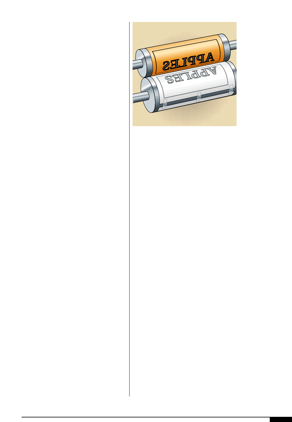
■ Press downtime will be reduced
■ Waste will be reduced
■ Quality will improve
■ Production will be better
BENEFITS OF
PRESS-RELATED PROOFING
ly and as evenly possible, using the brayer
roll. A sheet of white paper should be placed
under the transparent roll-out surface to
show the ink film applied. Keep the surface
and entire area clean, allowing only a mini-
mum of ink on the surface.
Note: Use a brayer or roller that is con-
centric, with no damage or dirt on the sur-
face. The rubber covering should be about
50 Shore “A” durometer.
Inking the Plates. Practice is required to
achieve a very thin, strong, even coat of ink
on the roll-out glass, brayer roll and the
mounted printing plate. The proper amount
of ink applied to the plate should be suffi-
cient to just fill the grain of the proofing
paper. Too little will show the white of the
paper within an area of supposed ink cover-
age, whether a large solid or a small halftone
dot. Too much will show excess pile-up,
either on the face of solids and dots, or out-
lining the solids and dots. Extreme excessive
inking will cause bridging from dot to dot
and small-type characters will fill in and not
be crisp or sharp. Examine the ink coverage
under a 20x magnifier to see that it is right.
After Inking. After the plates are inked, re-
examine the surface for evidence of brayer
marks, either of stops and starts or of brayer
edges – small ridges of ink. To remove any
brayer marks without adding more ink, roll a
nearly dry brayer over the plates repeatedly,
thereby smoothing out the ink.
Paralelling the Plate Cylinder. To ensure accu-
rate proofing, the plate cylinder must be par-
allel to the impression cylinder. Using a feel-
er gauge equal in thickness to the total of the
ideal plate and stickyback thickness, place
the gauge between the bare plate cylinder
and against the proofing paper that is taped
to the impression cylinder. Bring the plate
cylinder and impression cylinder together
until the gauge can be removed with mini-
mum drag. Gauge the opposite end and the
middle to make sure that drag resistance is
identical at all locations. If it is not, then the
machine must be reset before mounting.
Establishing Zero Contact. Even the most per-
fect plate, stickyback and plate-cylinder
combination will have some minor varia-
tions in concentricity and printing height.
The goal is to have all parts of all plates on a
given cylinder print up with a thin, strong,
continuous film of ink, with no portions
skipping or partially transferring ink, and no
portions so high as to over-impress and dis-
tort the image. When the plates are properly
inked, bring them into gradual contact with
the paper by rotating the print cylinder with
an oscillating movement. When the first visi-
ble ink is transferred (Figure
4@
), roll a com-
plete proof. “Zero contact” is that distance
between the plate cylinder and the impres-
sion cylinder that permits some small
amount of the total plate area to print up on
the proofing paper.
The mounting operator needs both judg-
ment and skill to achieve viable zero contact.
When proofing a cylinder mounted with mul-
tiple plates, a single spot of printing on the
proofing paper must be considered a high
spot and not a zero contact. On the other
hand, four or five large areas beginning to
print up on the proofing paper, may be con-
sidered excessive for zero contact, unless
they are exactly the same area on multiple
plates.
MOUNTING AND PROOFING 79
4@
Establishing zero
contact requires that all
parts of all plates on a
given cylinder print up
with a thin, strong,
continuous film of ink.
No portions can exhibit
signs of skipping or
partial ink transfer, and
no portions can meet so
high as to over-impress
and distort the image.
4@

80 FLEXOGRAPHY: PRINCIPLES AND PRACTICES
Setting the Gauges. Having established zero
contact, set the impression gauges on the
mounting and proofing machines to zero.
Obtaining a Complete Print. When proofing a
set of mounted plates, the goal is to get all
the print areas, on all the plates mounted on
the cylinder, to print completely with the
least possible additional impression of the
plates to the impression cylinder. For
process work, this should be minimal, gen-
erally within 0.001" additional impression.
Impression Tolerances. It is difficult to gener-
alize what constitutes good and bad impres-
sion tolerance because of the diversity of
plate thickness, mounting foam thickness
and other materials used in the vast field of
flexographic printing. Corrugated postprint
presses may use printing plates with 0.280"
of total mounting thickness, while small
label presses may only have 0.067" total
undercut. As a rough guide, a compression
of the plate material and mounting foam
equal to 2% of their total thickness should be
sufficient to proof print the images on the
plate.
On a typical press undercut for 0.125" addi-
tional impression from zero of 0.002" may be
the difference between good, sharp printing
and a completely unsatisfactory job. This
0.002" additional impression may produce
halos and fill-in while the job is being run.
The maximum allowable impression may be
different from one type of plate to another or
from one kind of print copy to another. All
large solids and large type will permit more
impression before distorting than will small
type, mechanical screens or halftone
process work.
Inking should always be consistent in film
thickness. However, if the plates on the
same cylinder contain both larger solids and
type and small type or dot work, then the
maximum tolerable impression is that
amount just before any of the copy becomes
distorted or enlarged with over-impression.
For process work, color keys made from
the finished negatives can serve as a goal for
ideal small-typeface appearances and ideal
halftone dot sizes in highlight, midtone and
shadow reverses.
Areas of poor or no ink transfer, known as
skip-outs, are a possible indication of low
areas that need to be built-up with make-
ready to print up without additional impres-
sion squeeze. False skip-outs may be caused
by incomplete plate ink-up, ink dried on the
plate before transfer, or low areas in the
proofing paper itself (usually not over
0.0005"). These last three possibilities should
be checked before using makeready by re-
inking the “skipping” area, rotating the
impression cylinder to a clean area on the
same paper and pulling a partial proof at the
same impression reading.
PREPRESS MAKEREADY
If several portions on all plates do not print
before the highest plate areas distort, two
options are available: raising low areas, or
lowering high areas.
Note: The following procedure is not rec-
ommended for process work. Plate cylinders,
bearings, stickyback and plate-thickness
variables for process work need to be hand
picked, measured and controlled so that the
whole plate area will print without visible
image growth or distortion.
Lowering High Areas
When using nonfoam or noncushion
stickyback, and with line work of various
configurations, the impression cylinder may
be utilized as an accurate smoothing and lev-
eling device.
Remove all ink from the plates and with
about 0.010" to 0.012" additional impression
from zero, rotate the plate cylinder against
the impression cylinder. This may “set” the
plates at the high points into the stickyback
and level them out.

Clean and re-ink the plates, find the new
zero contact (as it will likely be farther in
than the first contact because higher areas
have been lowered) and reproof the plates.
If the condition has improved but some
areas still do not print, the procedure may be
repeated with more impression, perhaps
0.00l5" without damage to the plates.
If the setting of the plates into the sticky-
back fails to produce acceptable results, the
plates must be removed from the cylinder
and another makeready technique applied.
If the irregularity was not found in pre-
mounting quality control of plates and cylin-
ders, the variation could be due to sticky-
back or plate-cylinder surface variations,
which are not discovered until initial proof-
ing on the mounter. The following procedure
may produce acceptable results.
1. Clearly outline the area needing correc-
tion. Lift the plate from the stickyback
by the end closest to the high plate area
until the backing substrate behind the
area is exposed. Take care not to distort
or crinkle the backing or move the plate
from its registered position. Isolated
high spots in photopolymer plates can
be successfully lowered by as much as
0.002" by manually sanding the backing
substrate.
2. Best results are obtained by removing
the plate from the cylinder and laying it
face or image area down on a smooth,
flat surface. The high spot should be
clearly identified and outlined and,
using a small piece of #400-grit wet or
dry finishing paper, gently sand the
plate backing substrate within the out-
lined area.
3. Finish by feathering the outer perimeter
of the sanded area. Be sure not to
remove too much material from the
backing sheet as this will cause a low
spot. Check your progress periodically
with the plate micrometer.
4. To avoid removing excessive film, peri-
odically lay the plate back down and
reproof it. At best, this is trial and error,
but with practice and observation, judg-
ment and skill will improve. As a result,
otherwise questionable plate/cylinder
relationships may be greatly improved.
This procedure has also proven helpful in
softening dots in vignetted areas of process
work. Although slightly more difficult to
sand, similar corrective action can be
accomplished with rubber and other syn-
thetic plate materials.
Building Up Low Areas
There are several ways of building up non-
printing areas or low spots in the plates.
Large low areas, or areas that do not print
up satisfactorily, after lowering the high
areas as discussed above, can be raised by
partially lifting the plate from the sticky-
back, applying a thin coat of liquid adhesive
to the back of the plate in the low areas and
resetting the plate on the stickyback.
Use a liquid adhesive from the plate manu-
facturer or plate-making material supplier, or
common rubber cement which is satisfactory
for this purpose. Dilute the cement with the
recommended solvent, then apply with a
clean brush in several thin layers, allowing
each layer to dry in turn. There is also the pos-
sible danger of swelling the plates. If the
cement is applied too heavily, remove the
excess adhesive. Use a flat, wide brush on
larger areas and a round brush for smaller
areas. Common shellac can also be used for
the same purpose; the buildup of each coat of
adhesive will vary with viscosity.
Another alternative to raise low areas in
the plate is double-sided adhesive tape,
which is available in various thicknesses,
ranging from 0.0009" to 0.005". Experience
with these techniques will make it possible
to determine very quickly, when looking at a
proof, just how much cement, shellac or
tape is required to build up a low spot.
MOUNTING AND PROOFING 81
82 FLEXOGRAPHY: PRINCIPLES AND PRACTICES
Composite Proof
After each cylinder has been proofed and
made ready as outlined above, a composite
proof of the entire job is made. As a guide to
the press operator, the composite proof
should be marked with the total amount of
impression required for each cylinder to
obtain a complete print up of all plates.
Any failure to get the same results on
press probably means the printing equip-
ment or the mounting and proofing machine
needs maintenance. Proper interpretation of
the handmade proof requires the under-
standing that plate flaws or printing irregu-
larities unacceptable on the press will not be
nearly as obvious. Close inspection is
required. One of the most important func-
tions of the mounting and proofing operator
is to read the final proof for correctness of
copy and freedom from errors. The final
proof should be folded into the finished
product to verify that all copy is in the right
place on all panels before the job is passed
to the pressroom for printing.
Edge Sealing
If the job is mounted for a long run or for
repeated runs, tape down or cement all plate
edges. This will prevent inks or plate-clean-
ing solutions from working under the plate
edges and dissolving or otherwise destroy-
ing the adhesive or cushion. There are spe-
cial edge-sealing cements available for this
purpose. Any good plastic adhesive tape will
also suffice. All edges and ends must be
rubbed down thoroughly.
Cleaning
After completing the mounting and proof-
ing, carefully wash and dry the printing
plates. Wash molded plates thoroughly with
alcohol and photopolymer plates with a mild
solution of soap and water. Grease spots, fin-
ger marks and other foreign matter on a
plate can repel ink from the print surface
and make it appear that the plate is not print-
ing properly. Proofing ink left on the plate
can cause fine type and dot work to build up
ink on press and cause dirty print, especially
if the proofing ink is oil-based and the press
ink is water-based.
Wrapping Mounted Cylinders
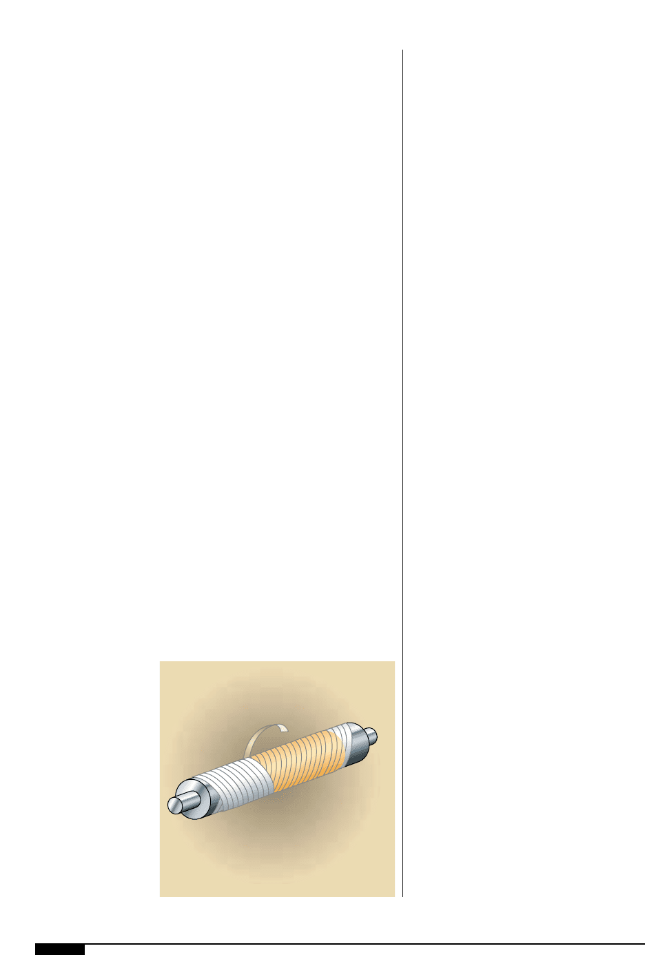
One way to assure a firm, complete bond
between the plate, stickyback and cylinder,
and to eliminate captive air pockets, is to
wrap a low density polyethylene film (about
2.5" wide) around the cylinder, completely
covering all plates mounted on it. Wrap the
tape around the cylinder in a spiral manner
from one end to the other, with each winding
overlapping the other, and then reversed to
crisscross back over the first layer of wind-
ings (Figure
4#
). Keep the tape tension tight,
but not too tight to compress the plates, pos-
sibly creating highs and lows. Secure the
tape end with a pressure-sensitive tape or by
tucking it under one of the last turns. The
wrap should remain in position at least sev-
eral hours, overnight if possible, but not
more than 24 hours. Mark the over-wrap
with the color, press number, station or deck
number, plus any other helpful information
to identify the job.
4#
Low density poly-
ethylene film is wrapped
in a spiral manner
around the cylinder from
one end to the other.
Each winding overlaps
the other, and then is
reversed to crisscross
back over the first layer
of winding. Wrapping
the mounted cylinder
this way eliminates
captive air pockets and
assures a firm complete
bond between plate,
stickyback and cylinder.
4#

MOUNTING AND PROOFING 83
ADDITIONAL OFF-LINE
TIME SAVERS
To reduce downtime and waste during a
job set-up on press, there are several addi-
tional steps that can be taken while the job is
in the mounting and proofing machine.
Web-edge Guide Marks
To identify the precise edges of the press
web, mount two small plates in the trim
area. The plates have a printable line about
the thickness of a pencil line (1 pt.) and
about 0.125" to 0.25" long. From these print-
ed lines, the press operator can quickly see
where to establish lateral web position in
relation to the copy and be assured the edge
guide is holding it in place during the run.
Web-trim Mark
When a web-stock slightly wider than that
required for the job is printed, and a selvage
edge must be trimmed, a small plate is mount-
ed (as above) to identify the correct location
for the trim knife. This permits the press oper-
ator to set the knife quickly and accurately,
and to check its position on each roll change,
web break or stock-width variation.
Slitter-knife Marks
The same principle can be applied in locat-
ing multiple-up slitting-knife locations. It
assures quick knife positioning at setup and
is a constant reminder of any knife slippage
or web deviation.
Bag-folds, Former-guide Marks
After multiwall bags are printed, the web
is folded into a tube in which formers are set
to create side folds and gussets. The web-
marking principle can be applied to locating
the formers. The small marks are located at
bag cutoff and will not be visible in the fin-
ished bag. The final proof, containing all of
the above information, is used to check the
job thoroughly for just about every possible
requirement, except the actual color.

84 FLEXOGRAPHY: PRINCIPLES AND PRACTICES
M
ounting systems designed
and developed for the
flexographic printing in-
dustry, have enhanced
the accuracy of prepress
plate positioning in regis-
tration. Press time has been diminished as a
result. This section discusses the compo-
nents of the different mounting systems on
the market today, as well as the advantages
of the process and the preparation practices
necessary to the success of these latest
technololgies.
COMPUTERIZED MOUNTING
AND PROOFING SYSTEM
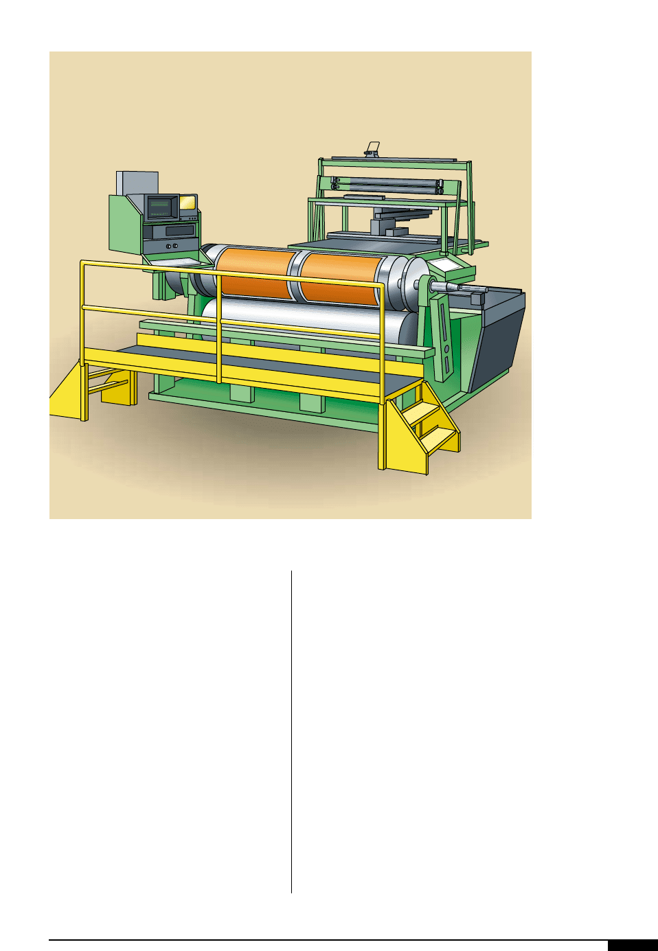
Computerized mounting systems were
introduced to the flexo industry for both
wide-web substrates and corrugated pre-
print liner in recent years. These mounting
systems are available in a range of sizes for
plate cylinders, from 60" to 120" with asso-
ciated cylinder-repeat sizes (Figure
4)
).
The systems do not use conventional pins or
punching of plates and negatives. They use
conventional stickyback for holding plates
to sleeves or integral printing cylinders.
Accurate registration is aided by micro-
video cameras and monitors that magnify
register marks 30x to 40x actual size for visu-
al alignment, making it possible to position
plates across and around a given cylinder to
within a tolerance of 0.002". All preliminary
functions are programmed into the machine,
allowing the operator to complete the plate-
mounting process rapidly.
The following is an abbreviated series of
procedural steps for operating the system:
1. Select the proofing paper or other
proofing material and place it on the
impression cylinder. This may be done
manually or automatically.
2. Bring the printing cylinder into position
and lock in place. Apply stickyback to
the plate cylinder, either automatically
or manually.
3. Lower the plate hold-down table ito a
predetermined position relative to the
plate cylinder.
4. Place the plate on the hold-down table,
allowing a portion of the plate to hang
over the front edge of the table. Turn
the vacuum on to hold the plate in posi-
tion to the table.
5. Move the microvideo camera over a
defined register mark on the plate and
enter the position into the computer.
Locate a second register point on the
plate and enter this into the computer.
6. The computer determines the position
of the plate on the hold-down table and
moves the table to bring the plate square
with the cylinder face. Position the plate
relative to the centerline or any desig-
nated point on the plate cylinder.
7. Two pressure rollers contact the over-
hanging portion of the printing plate,
attaching it to the stickyback and holding
it in place while the vacuum is shut off.
8. As the computer rotates the plate cylin-
Recent Introductions in
Mounting Equipment Systems
der, the pressure rollers gradually apply
the plate to the stickyback and the plate
is mounted.
9. The plate is inked and proofed. The
proofing cylinder moves down and
away, allowing the plate cylinder to be
removed and the next cylinder brought
into position.
These steps are repeated with each plate
to be mounted, substantially cutting mount-
ing time, especially in three- or four-color
process work.
PIN-REGISTER
MOUNTING SYSTEM I
Pin-registration systems have been used
for many years in letterpress and offset print-
ing. Adaptation of these methods to flexogra-
phy has not been easy in the past because of
dimensionally unstable rubber plates and the
large cylinder inventories used for variable
repeat lengths in packaging markets.
Availability of dimensionally stable photo-
polymer plates allowed pin registration to
become a reality in flexographic printing.
Operating Principles
The pin-registration system, used in other
printing technologies, consists of producing
accurately sized and positioned holes for reg-
istration pins. In practice, this usually
involves punching holes in the films, plates
and press cylinders, and positioning these
materials on register pins during all steps of
MOUNTING AND PROOFING 85
4$
Computerized mounting
and proofing systems
were introduced to
provide greater
accuracy and efficiency.
They use conventional
stickyback for holding
plates to sleeves or
integral printing
cylinders, instead of
pins. Punching of plates
and negatives is not
necessary.
4$
