Fitzgerald A.E. Electric Machinery
Подождите немного. Документ загружается.

266 CHAPTER 5 Synchronous Machines
5.4 STEADY-STATE POWER-ANGLE
CHARACTERISTICS
The maximum power a synchronous machine can deliver is determined by the max-
imum torque which can be applied without loss of synchronism with the external
system to which it is connected. The purpose of this section is to derive expressions
for the steady-state power limits of synchronous machines in simple situations for
which the external system can be represented as an impedance in series with a voltage
source.
Since both the external system and the machine itself can be represented as an
impedance in series with a voltage source, the study of power limits becomes merely
a special case of the more general problem of the limitations on power flow through
a series impedance. The impedance will include the synchronous impedance of the
synchronous machine as well as an equivalent impedance of the external system
(which may consist of transmission lines and transformer banks as well as additional
synchronous machines).
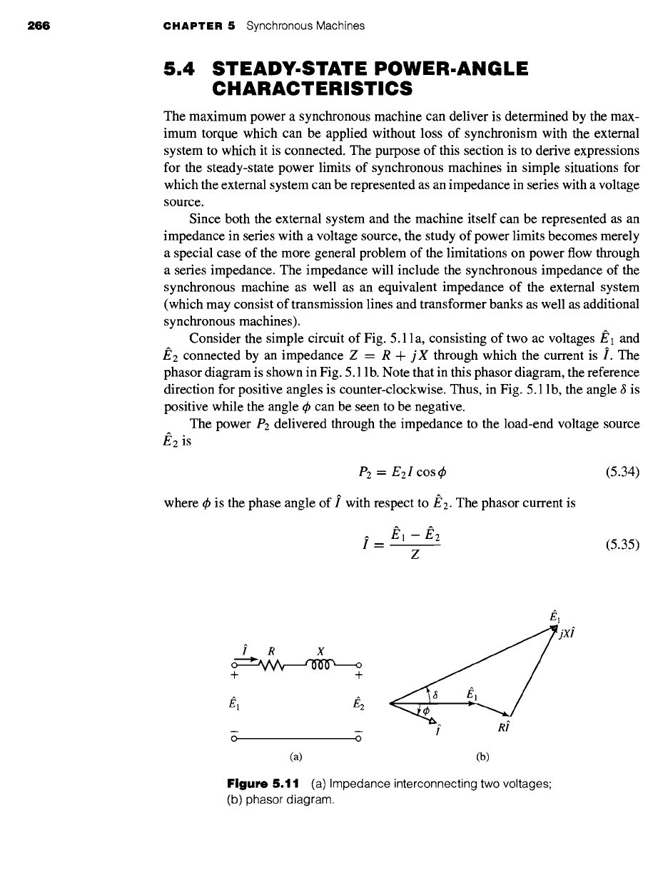
Consider the simple circuit of Fig. 5.11 a, consisting of two ac voltages/~ 1 and
/~2 connected by an impedance Z = R -F jX through which the current is i. The
phasor diagram is shown in Fig. 5.1 lb. Note that in this phasor diagram, the reference
direction for positive angles is counter-clockwise. Thus, in Fig. 5.11 b, the angle 6 is
positive while the angle 4) can be seen to be negative.
The power P2 delivered through the impedance to the load-end voltage source
/~2 is
P2 = E21 cos 4) (5.34)
where 4) is the phase angle of i with respect to/~2. The phasor current is
i = #~ - ~2 (5.35)
Z
i R X
o ~ o
+ +
#l #2
O O
[ Ri
(a) (b)
Figure
5.11 (a) Impedance interconnecting two voltages;
(b) phasor diagram.
S,4 Steady-State Power-Angle Characteristics 26"t
If the phasor voltages and the impedance are expressed in polar form,
F,
1 =
E1 e ja
F-,2 ~-- E2
Z = R + j X
= IZl e joz
(5.36)
(5.37)
(5.38)
where 8 is the phase angle by which E1 leads/~2
and
4~z = tan -1
(X/R)
is the phase
angle of the impedance Z, then
I. I
e j~ E1 e j8 -- E2
E1
ej(8_4,z) E2 -j4~z
= = = ~ - ~ e (5.39)
IZl eJOz IZl IZl
Taking the real part of Eq. 5.39 gives
E~ E2
I cos q~ = cos (8 - q~z) - ~ cos (-q~z) (5.40)
IZl IZl
Noting that cos (-4~z)=cos4~z =
R/IZI
we see that substitution of Eq. 5.40 in
Eq. 5.34 gives
E1E2 E2 R
P: = ~ cos (8 - 4~z) (5.41)
IZl IZl 2
or
P2 ----- E1E2 sin
(8 + otz)
E~R
(5.42)
IZl IZl =
where
otz=90°-q~z=tan-l(R)
(5.43)
Similarly power P1 at source end/~1 of the impedance can be expressed as
E1Ee E21R
P1 = ~ sin (8 -- C~z) + ~ (5.44)
IZl IZl 2
If, as is frequently the case, the resistance is negligible, then R << [Z[, [Z[ ~ X and
az ~ 0 and hence
P1 = P2 = E1 E2 sin 8 (5.45)
X
Equation 5.45 is a very important equation in the study of synchronous machines
and indeed in the study of ac power systems in general. When applied to the situation
of a synchronous machine connected to an ac system, Eq. 5.45 is commonly referred
to as the
power-angle characteristic
for a synchronous machine, and the angle 8 is
known as the
power angle.
If the resistance is negligible and the voltages are constant,
268 CHAPTER 5 Synchronous Machines
then from Eq. 5.45 the maximum power transfer
E1E2
Pl,max = e2,max--" X (5.46)
occurs when ~ = 4-90 °. Note that if ~ is positive, E1 leads E2 and, from Eq. 5.45,
power flows from source E 1 to E2. Similarly, when ~ is negative, E1 lags E2 and power
flows from source E2 to El.
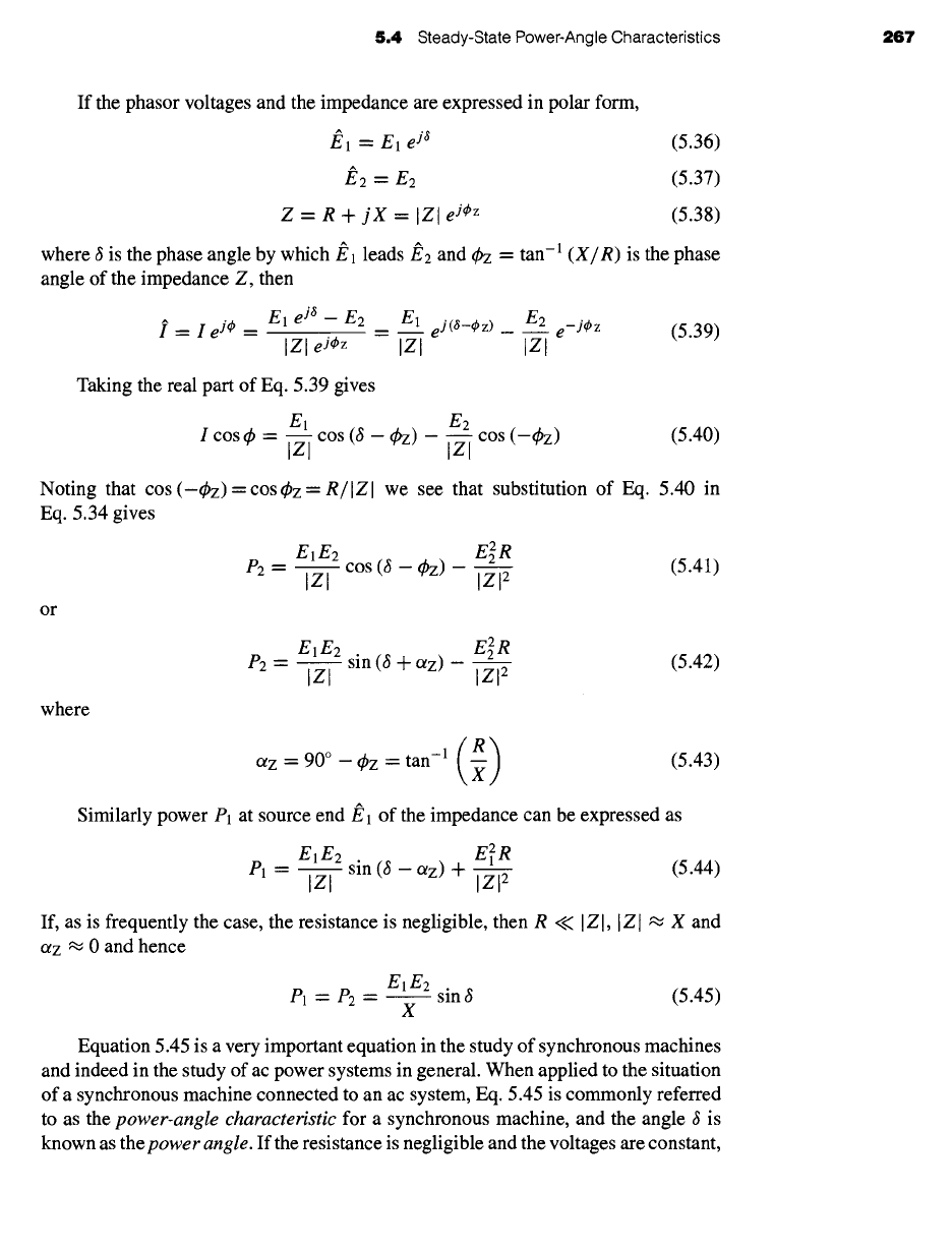
Equation 5.45 is valid for any voltage sources E1 and E2 separated by a reactive
impedance j X. Thus for a synchronous machine with generated voltage
J~af
and
synchronous reactance Xs connected to a system whose Thevenin equivalent is a
voltage
source
VEQ in series with a reactive impedance j XEQ, as shown in Fig. 5.12,
the power-angle characteristic can be written
p = EafVEQ sin ~ (5.47)
Xs "l- XEQ
where P is the power transferred from the synchronous machine to the system and
is the phase angle
of/~af
with respect to f'EQ.
In a similar fashion, it is possible to write a power-angle characteristic in terms of
Xs, Eaf, the terminal voltage Va, and the relative angle between them, or alternatively
XEQ, Va and
VEQ
and their relative angle. Although these various expressions are
equally valid, they are not equally useful. For example, while Eaf and
VEQ
remain
constant as P is varied, Va will not. Thus, while Eq. 5.47 gives an easily solved relation
between P and d;, a power-angle characteristic based upon Va cannot be solved without
an additional expression relating Va to P.
It should be emphasized that the derivation of Eqs. 5.34 to 5.47 is based on
a single-phase ac circuit. For a balanced three-phase system, if El and E2 are the
line-neutral voltages, the results must be multiplied by three to get the total three-
phase power; alternatively E1 and E2 can be expressed in terms of the line-to-line
voltage (equal to ~/3 times the line-neutral voltage), in which case the equations give
three-phase power directly.
When the power expression of Eq. 5.45 is compared with the expression of
Eq. 5.1 for torque in terms of interacting flux and mmf waves, they are seen to
Xs XEQ
o
+
+ +
Ea o
k )k
2
y y-
Generator Thevenin equivalent
for the external system
Figure 5.12
Equivalent-circuit representation
of a synchronous machine connected to an
external system.

5.4 Steady-State Power-Angle Characteristics 269
be of the same form. This is no coincidence. Remember that torque and power are
proportional when, as here, speed is constant. What we are really saying is that Eq. 5.1,
applied specifically to an idealized cylindrical-rotor machine and translated to circuit
terms, becomes Eq. 5.45. A quick mental review of the background of each relation
should show that they stem from the same fundamental considerations.
From Eq. 5.47 we see that the maximum power transfer associated with
synchronous-machine operation is proportional to the magnitude of the system volt-
age, corresponding to VEQ, as well as to that of the generator internal voltage Eaf.
Thus, for constant system voltage, the maximum power transfer can be increased by
increasing the synchronous-machine field current and thus the internal voltage. Of
course, this cannot be done without limit; neither the field current nor the machine
fluxes can be raised past the point where cooling requirements fail to be met.
In general, stability considerations dictate that a synchronous machine achieve
steady-state operation for a power angle considerably less than 90 °. Thus, for a given
system configuration, it is necessary to ensure that the machine will be able to achieve
its rated operation and that this operating condition will be within acceptable operating
limits for both the machine and the system.
EXAMPLE 5.(
A three-phase, 75-MVA, 13.8-kV synchronous generator with saturated synchronous reactance
Xs -- 1.35 per unit and unsaturated synchronous reactance Xs,u -- 1.56 per unit is connected to
an external system with equivalent reactance XEQ "-" 0.23 per unit and voltage VEQ -- 1.0 per
unit, both on the generator base. It achieves rated open-circuit voltage at a field current of
297 amperes.
@
a. Find the maximum power Pmax (in MW and per unit) that can be supplied to the external
system if the internal voltage of the generator is held equal to 1.0 per unit.
b. Using MATLAB, t plot the terminal voltage of the generator as the generator output is
varied from zero to Pmax under the conditions of part (a).
c. Now assume that the generator is equipped with an
automatic voltage regulator
which
controls the field current to maintain constant terminal voltage. If the generator is loaded
to its rated value, calculate the corresponding power angle, per-unit internal voltage, and
field current. Using MATLAB, plot per-unit Ear as a function of per-unit power.
II
Solution
a. From Eq. 5.47
Eaf VEQ
Pmax -- Ss + XEQ
Note that although this is a three-phase generator, no factor of 3 is required because we are
working in per unit.
t MATLAB is a registered trademark of The MathWorks, Inc.
270 CHAPTER
5 Synchronous Machines
Terminal voltage vs. power angle for part (b)
1
0.98
"~ 0.96
~ 0.94
"~ 0.92
~ 0.9
0.88
0.86
0 10 20 30 40 50 60 70 80 90
Power angle, delta [degrees]
(a)
,.a
.,..~
1.8
1.7
1.6
1.5
1.4
1.3
1.2
1.1
Eaf vs. power for part (c)
I I I I I I I I I
0 0.1 0.2 0.3 0.4 0.5 0.6 0.7 0.8 0.9
Power [per unit]
(b)
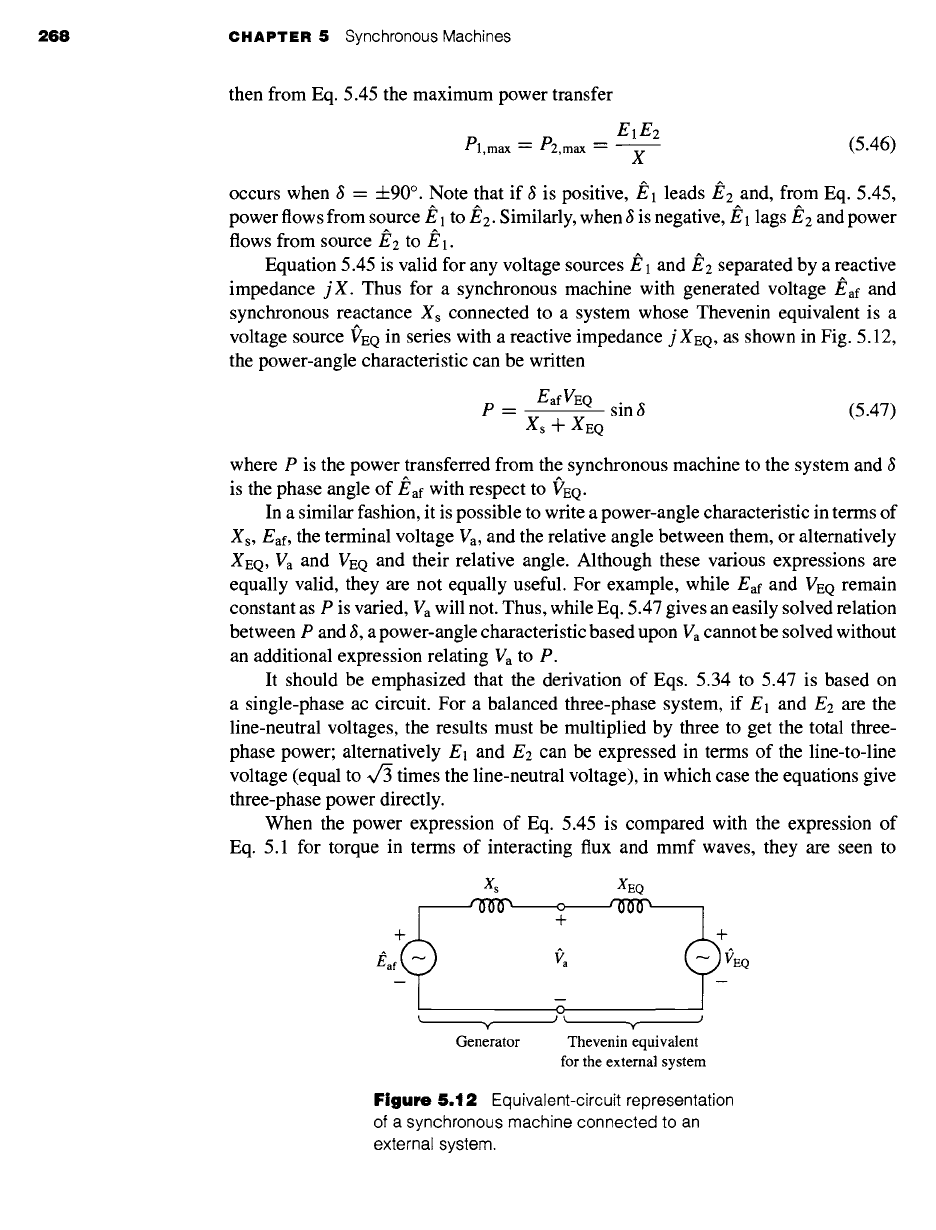
Figure 5.13 Example 5.6. (a) MATLAB plot of terminal voltage vs.
for part (b). (b) MATLAB plot of
Eaf vs.
power for part (c).
S,4 Steady-State Power-Angle Characteristics 2"1t
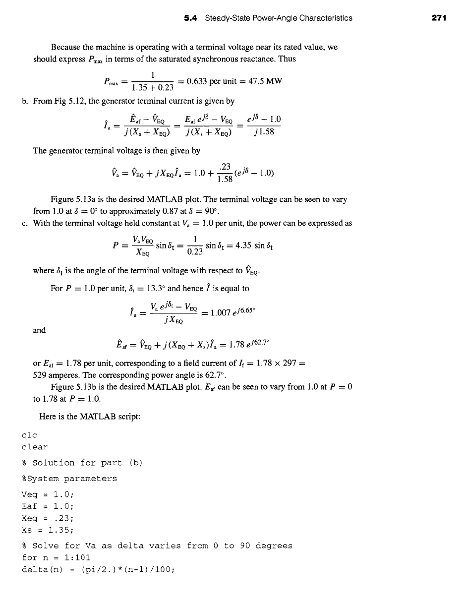
Because the machine is operating with a terminal voltage near its rated value, we
should express Pmax in terms of the saturated synchronous reactance. Thus
1
Pmax 1.35 + 0.23 = 0.633 per unit 47.5 MW
b.
From Fig 5.12, the generator terminal current is given by
J~af- VEQ
Eaf
eft--
VEQ _
eft--
1.0
ia -- j (X s -']- XEQ ) = j (X s -~- XEQ ) -- jl.58
The generator terminal voltage is then given by
.23
vl~ra : T~rEQ + jXEQIa ~---
1.0 +
1-~(e jS-
1.0)
Figure 5.13a is the desired MATLAB plot. The terminal voltage can be seen to vary
from 1.0 at 8 = 0 ° to approximately 0.87 at 8 = 90 °.
c. With the terminal voltage held constant at Va = 1.0 per unit, the power can be expressed as
P
= Va VEQ
sin 8 t = ~1 sin 8 t = 4.35 sin 8 t
XEQ 0.23
where 8 t is the angle of the terminal voltage with respect to ("EQ.
For P = 1.0 per unit,
~t =
13.3 ° and hence i is equal to
~lla ~- Va
eJSt_
VEQ __ 1.007 e j6"65°
jXEQ
and
#af = ]~'rEQ +
j(XEQ
+ Xs)/~a =
1.78 e j62"7°
or Eaf = 1.78 per unit, corresponding to a field current of If = 1.78 x 297 =
529 amperes. The corresponding power angle is 62.7 ° .
Figure 5.13b is the desired MATLAB plot.
Eaf can
be seen to vary from 1.0 at P = 0
to 1.78 at P = 1.0.
Here is the MATLAB script:
clc
clear
% Solution for part (b)
%System parameters
Veq = 1.0;
Eaf = 1.0;
Xeq = .23;
Xs = 1.35;
% Solve for Va as delta varies from 0 to 90 degrees
for n = i:i01
delta(n) = (pi/2.)*(n-1)/100;
272 CHAPTER 5 Synchronous Machines
Ia(n) : (Eaf *exp(j*delta(n)) - Veq)/(j* (Xs + Xeq) ) ;
Va(n) = abs(Veq + j*Xeq*Ia(n)) ;
degrees(n) = 180*delta(n)/pi;
end
%Now plot the results
plot (degrees, Va)
xlabel('Power angle, delta [degrees]')
ylabel('Terminal voltage [per unit] ')
title( 'Terminal voltage vs. power angle for part (b)')
fprintf('\n\nHit any key to continue\n')
pause
% Solution for part (c)
%Set terminal voltage to unity
Vterm : 1.0;
for n : i:i01
P(n) : (n-l)/100;
deltat(n) = asin(P(n)*Xeq/(Vterm*Veq)) ;
Ia(n) = (Vterm *exp(j*deltat(n)) - Veq) / (j*Xeq) ;
Eaf(n) = abs(Vterm + j*(Xs+Xeq)*Ia(n) ) ;
end
%Now plot the results
plot (P, Eaf)
xlabel ( ' Power [per unit ] ' )
ylabel('Eaf [per unit] ')
title('Eaf vs. power for part (c) ')
Consider the 75-MVA, 13.8 kV machine of Example 5.6. It is observed to be operating at
terminal voltage of 13.7 kV and an output power of 53 MW at 0.87 pf lagging. Find (a) the
phase current in kA, (b) the internal voltage in per unit, and (c) the corresponding field current
in amperes.
Solution
a. /a = 2.57 kA
b. Eaf = 1.81 per unit
c. If = 538 amperes
!XAMPLE 5.1
A 2000-hp, 2300-V, unity-power-factor, three-phase, Y-connected, 30-pole, 60-Hz synchronous
motor has a synchronous reactance of 1.95 ~2/phase. For this problem all losses may be
neglected.
5.4 Steady-State Power-Angle Characteristics 273
ia
Xs m
ia f'a ia
Xsg
Xs m
.~ ~ ~ j~aXsm "-
+ + + +
^
afm Ea
m
O
(a) (b) (c)
+
afro
^
/ ia f:a
--arm
jiaXsg
jiaXsm
^
Eafg
ia
.^
#afm
(d) (e)
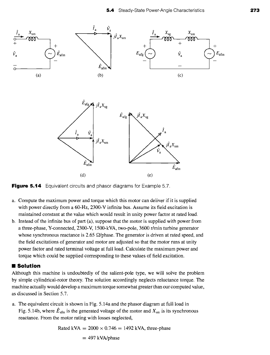
Figure 5.14 Equivalent circuits and phasor diagrams for Example 5.7.
a. Compute the maximum power and torque which this motor can deliver if it is supplied
with power directly from a 60-Hz, 2300-V infinite bus. Assume its field excitation is
maintained constant at the value which would result in unity power factor at rated load.
b. Instead of the infinite bus of part (a), suppose that the motor is supplied with power from
a three-phase, Y-connected, 2300-V, 1500-kVA, two-pole, 3600 r/min turbine generator
whose synchronous reactance is 2.65 g2/phase. The generator is driven at rated speed, and
the field excitations of generator and motor are adjusted so that the motor runs at unity
power factor and rated terminal voltage at full load. Calculate the maximum power and
torque which could be supplied corresponding to these values of field excitation.
II Solution
Although this machine is undoubtedly of the salient-pole type, we will solve the problem
by simple cylindrical-rotor theory. The solution accordingly neglects reluctance torque. The
machine actually would develop a maximum torque somewhat greater than our computed value,
as discussed in Section 5.7.
a. The equivalent circuit is shown in Fig. 5.14a and the phasor diagram at full load in
Fig. 5.14b,
where
#afm is the generated voltage of the motor and Xsm is its synchronous
reactance. From the motor rating with losses neglected,
Rated kVA = 2000 × 0.746 = 1492 kVA, three-phase
= 497 kVA/phase
274 CHAPTER
5 Synchronous Machines
Rated voltage --
Rated current -
2300
4~
-- 1328 V line-to-neutral
497,000
1328
= 374 A/phase-Y
From the phasor diagram at full load
Eaf m "- v/V) + (laXsm) 2 -- 1515 W
When the power source is an infinite bus and the field excitation is constant, Va and
Ear m are constant. Substitution of Va for El, Eafm for E2, and Xsm for X in Eq. 5.46 then
gives
VaEafm 1328 × 1515
Pmax = = = 1032 kW/phase
Xsm 1.95
= 3096 kW, three-phase
In per unit, Pmax = 3096/1492 = 2.07 per unit. Because this power exceeds the motor
rating, the motor cannot deliver this power for any extended period of time.
With 30 poles at 60 Hz, the synchronous angular velocity is found from Eq. 4.40
o& = we = (2zr60) = 8zr rad/sec
and hence
Pmax 3096 x 103
Tmax = = = 123.2 kN. m
Ogs 8zr
b. When the power source is the turbine generator, the equivalent circuit becomes that shown
^
in Fig. 5.14c, where Eafg is the generated voltage of the generator and Xsg is its
synchronous reactance. Here the synchronous generator is equivalent to an external
voltage f'EQ and reactance XEQ as in Fig. 5.12. The phasor diagram at full motor load,
unity power factor, is shown in Fig. 5.14d. As before, Va = 1330 V/phase at full load and
Eafm "- 1515 V/phase.
From the phasor diagram
Eafg--- w/Vt 2 + (laXsg) 2= 1657 V
Since the field excitations and speeds of both machines are constant, Eafg and Eafm are
constant. Substitution of Eafg for El, Eafm for E2, and Xsg + Xsm for X in Eq. 5.46 then
gives
EafgEafm 1657 x 1515
Pmax -- Xsg + Xsm =
4.60 = 546 kW/phase
= 1638 kW, three-phase
In per unit, Pmax = 1638/1492 = 1.10 per unit.
Pmax 1635 × 103
Tma x -~- -- --
65.2 kN. m
Ogs 8zr
5.5 Steady-State Operating Characteristics 275
Synchronism would be lost if a load torque greater than this value were applied to
the motor shaft. Of course, as in part (a), this loading exceeds the rating of the motor and
could not be sustained under steady-state operating conditions.
~ractice Problem 5.q
If the excitation system of the generator of Example 5.7 becomes damaged and must be limited
to supplying only one half of the field excitation of part (b) of the example, calculate the
maximum power which can be supplied to the motor.
Solution
819 kW
5.5
STEADY-STATE OPERATING
CHARACTERISTICS
The principal steady-state operating characteristics of a synchronous machine are
described by the interrelations between terminal voltage, field current, armature cur-
rent, power factor, and efficiency. A selection of performance curves of importance
in practical application of synchronous machines are presented here.
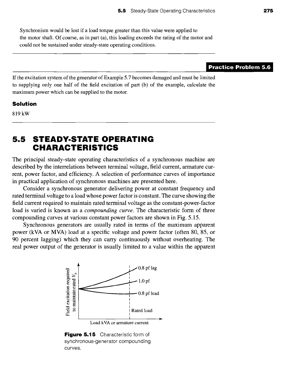
Consider a synchronous generator delivering power at constant frequency and
rated terminal voltage to a load whose power factor is constant. The curve showing the
field current required to maintain rated terminal voltage as the constant-power-factor
load is varied is known as a
compounding curve.
The characteristic form of three
compounding curves at various constant power factors are shown in Fig. 5.15.
Synchronous generators are usually rated in terms of the maximum apparent
power (kVA or MVA) load at a specific voltage and power factor (often 80, 85, or
90 percent lagging) which they can carry continuously without overheating. The
real power output of the generator is usually limited to a value within the apparent
.,..~
I~ 0.8 pf lag
1.0 pf
0.8 pf lead
Rated load
Load kVA or armature current
Figure
5.15 Characteristic form of
synchronous-generator compounding
curves.