Fitzgerald A.E. Electric Machinery
Подождите немного. Документ загружается.

236 CHAPTER 4 Introduction to Rotating Machines
thoroughly for dc machines in Chapter 7. Faraday's law results in Eq. 4.50 for the
rms voltage generated in an ac machine winding or Eq. 4.53 for the average voltage
generated between brushes in a dc machine.
On examination of the mmf wave of a three-phase winding, we found that bal-
anced three-phase currents produce a constant-amplitude air-gap magnetic field rotat-
ing at synchronous speed, as shown in Fig. 4.31 and Eq. 4.39. The importance of this
fact cannot be overstated, for it means that it is possible to operate such machines, ei-
ther as motors or generators, under conditions of constant torque (and hence constant
electrical power as is discussed in Appendix A), eliminating the double-frequency,
time-varying torque inherently associated with single-phase machines. For example,
imagine a multimegawatt single-phase 60-Hz generator subjected to multimegawatt
instantaneous power pulsation at 120 Hz! The discovery of rotating fields led to the
invention of the simple, rugged, reliable, self-starting polyphase induction motor,
which is analyzed in Chapter 6. (A single-phase induction motor will not start; it
needs an auxiliary starting winding, as shown in Chapter 9.)
In single-phase machines, or in polyphase machines operating under unbalanced
conditions, the backward-rotating component of the armature mmf wave induces
currents and losses in the rotor structure. Thus, the operation of polyphase machines
under balanced conditions not only eliminates the second-harmonic component of
generated torque, it also eliminates a significant source of rotor loss and rotor heating.
It was the invention of polyphase machines operating under balanced conditions that
made possible the design and construction of large synchronous generators with
ratings as large as 1000 MW.
Having assumed sinusoidally-distributed magnetic fields in the air gap, we then
derived expressions for the magnetic torque. The simple physical picture for torque
production is that of two magnets, one on the stator and one on the rotor, as shown
schematically in Fig. 4.35a. The torque acts in the direction to align the magnets.
To get a reasonably close quantitative analysis without being hindered by details, we
assumed a smooth air gap and neglected the reluctance of the magnetic paths in the
iron parts, with a mental note that this assumption may not be valid in all situations
and a more detailed model may be required.
In Section 4.7 we derived expressions for the magnetic torque from two view-
points, both based on the fundamental principles of Chapter 3. The first viewpoint
regards the machine as a set of magnetically-coupled circuits with inductances which
depend on the angular position of the rotor, as in Section 4.7.1. The second regards the
machine from the viewpoint of the magnetic fields in the air gap, as in Section 4.7.2.
It is shown that the torque can be expressed as the product of the stator field, the rotor
field, and the sine of the angle between their magnetic axes, as in Eq. 4.73 or any of
the forms derived from Eq. 4.73. The two viewpoints are complementary, and ability
to reason in terms of both is helpful in reaching an understanding of how machines
work.
This chapter has been concerned with basic principles underlying rotating-
machine theory. By itself it is obviously incomplete. Many questions remain unan-
swered. How do we apply these principles to the determination of the characteristics
of synchronous, induction, and dc machines? What are some of the practical problems
4.12 Problems 237
that arise from the use of iron, copper, and insulation in physical machines? What
are some of the economic and engineering considerations affecting rotating-machine
applications? What are the physical factors limiting the conditions under which a
machine can operate successfully? Appendix D discusses some of these problems.
Taken together, Chapter 4 along with Appendix D serve as an introduction to the more
detailed treatments of rotating machines in the following chapters.
4.12 PROBLEMS
4.1 The rotor of a six-pole synchronous generator is rotating at a mechanical
speed of 1200 r/min.
a. Express this mechanical speed in radians per second.
b. What is the frequency of the generated voltage in hertz and in radians per
second?
c. What mechanical speed in revolutions per minute would be required to
generate voltage at a frequency of 50 Hz?
4.2 The voltage generated in one phase of an unloaded three-phase synchronous
generator is of the form
v(t) = Vo
cos cot. Write expressions for the voltage in
the remaining two phases.
4.3 A three-phase motor is used to drive a pump. It is observed (by the use of a
stroboscope) that the motor speed decreases from 898 r/min when the pump
is unloaded to 830 r/min as the pump is loaded.
a. Is this a synchronous or an induction motor?
b. Estimate the frequency of the applied armature voltage in hertz.
c. How many poles does this motor have?
4.4 The object of this problem is to illustrate how the armature windings of
certain machines, i.e., dc machines, can be approximately represented by
uniform current sheets, the degree of correspondence growing better as the
winding is distributed in a greater number of slots around the armature
periphery. For this purpose, consider an armature with eight slots uniformly
distributed over 360 electrical degrees (corresponding to a span of one pole
pair). The air gap is of uniform length, the slot openings are very small, and
the reluctance of the iron is negligible.
Lay out 360 electrical degrees of the armature with its slots in developed
form in the manner of Fig. 4.23a and number the slots 1 to 8 from left to right.
The winding consists of eight single-turn coils, each carrying a direct current
of 10 A. Coil sides placed in any of the slots 1 to 4 carry current directed into
the paper; those placed in any of the slots 5 to 8 carry current out of the paper.
a. Consider that all eight slots are placed with one side in slot 1 and the other
in slot 5. The remaining slots are empty. Draw the rectangular mmf wave
produced by these slots.
b. Next consider that four coils have one side in slot 1 and the other in slot 5,
while the remaining four coils have one side in slot 3 and the other in
238
CHAPTER 4 Introduction to Rotating Machines
slot 7. Draw the component rectangular mmf waves produced by each
group of coils, and superimpose the components to give the resultant
mmf wave.
c. Now consider that two coils are placed in slots 1 and 5, two in slots 2 and
6, two in 3 and 7, and two in 4 and 8. Again superimpose the component
rectangular waves to produce the resultant wave. Note that the task can be
systematized and simplified by recognizing that the mmf wave is
symmetric about its axis and takes a step at each slot which is directly
proportional to the number of ampere-conductors in that slot.
d. Let the armature now consist of 16 slots per 360 electrical degrees with
one coil side per slot. Draw the resultant mmf wave.
4.5 A
three-phase Y-connected ac machine is initially operating under balanced
three-phase conditions when one of the phase windings becomes
open-circuited. Because there is no neutral connection on the winding, this
requires that the currents in the remaining two windings become equal and
opposite. Under this condition, calculate the relative magnitudes of the
resultant positive- and negative-traveling mmf waves.
4.6 What is the effect on the rotating mmf and flux waves of a three-phase
winding produced by balanced-three-phase currents if two of the phase
connections are interchanges?
4.7 In a balanced two-phase machine, the two windings are displaced 90 electrical
degrees in space, and the currents in the two windings are phase-displaced 90
electrical degrees in time. For such a machine, carry out the process leading
to an equation for the rotating mmf wave corresponding to Eq. 4.39 (which is
derived for a three-phase machine).
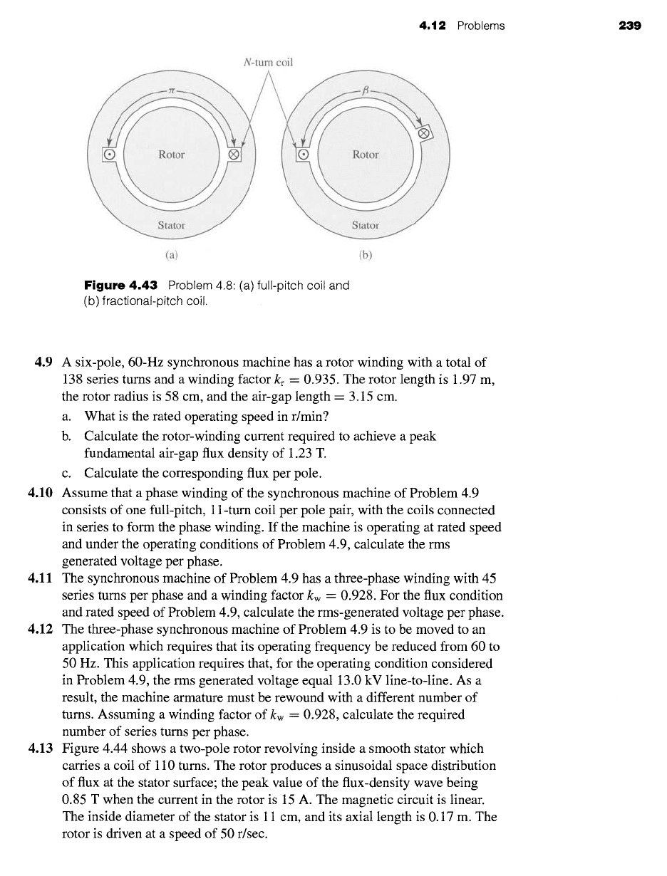
4.8 This problem investigates the advantages of short-pitching the stator coils of
an ac machine. Figure 4.43a shows a single full-pitch coil in a two-pole
machine. Figure 4.43b shows a fractional-pitch coil for which the coil sides
are fl radians apart, rather than zr radians (180 °) as is the case for the
full-pitch coil.
For an air-gap radial flux distribution of the form
-- Z Bn
cos
nO
Br
n odd
where n = 1 corresponds to the fundamental space harmonic, n -- 3 to the
third space harmonic, and so on, the flux linkage of each coil is the integral
of Br over the surface spanned by that coil. Thus for the nth space harmonic,
the ratio of the maximum fractional-pitch coil flux linkage to that of the
full-pitch coil is
ff/2 B,,
cos
nO dO
f/~/2
fl/2 3-[3/2
COS
nO dO
= = Isin
(nil~2)]
f_~/2
Bn
cos
nO dO
fzr/2
:rr/2 3-:rr/2
COS
nO dO
It is common, for example, to fractional-pitch the coils of an ac machine
by 30 electrical degrees (/3 = 5zr/6 - 150°). For n -- 1, 3, 5 calculate the
fractional reduction in flux linkage due to short pitching.
4.12 Problems 239
N-turn coil
(a) (b)
Figure
4.43 Problem 4.8 (a) full-pitch coil and
(b) fractional-pitch coil.
4.9 A six-pole, 60-Hz synchronous machine has a rotor winding with a total of
138 series turns and a winding factor kr - 0.935. The rotor length is 1.97 m,
the rotor radius is 58 cm, and the air-gap length = 3.15 cm.
a. What is the rated operating speed in r/min?
b. Calculate the rotor-winding current required to achieve a peak
fundamental air-gap flux density of 1.23 T.
c. Calculate the corresponding flux per pole.
4.10 Assume that a phase winding of the synchronous machine of Problem 4.9
consists of one full-pitch, 11-turn coil per pole pair, with the coils connected
in series to form the phase winding. If the machine is operating at rated speed
and under the operating conditions of Problem 4.9, calculate the rms
generated voltage per phase.
4.11 The synchronous machine of Problem 4.9 has a three-phase winding with 45
series turns per phase and a winding factor kw -- 0.928. For the flux condition
and rated speed of Problem 4.9, calculate the rms-generated voltage per phase.
4.12 The three-phase synchronous machine of Problem 4.9 is to be moved to an
application which requires that its operating frequency be reduced from 60 to
50 Hz. This application requires that, for the operating condition considered
in Problem 4.9, the rms generated voltage equal 13.0 kV line-to-line. As a
result, the machine armature must be rewound with a different number of
turns. Assuming a winding factor of kw = 0.928, calculate the required
number of series turns per phase.
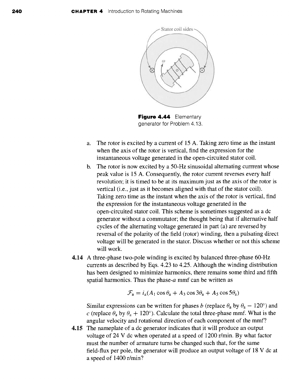
4.13 Figure 4.44 shows a two-pole rotor revolving inside a smooth stator which
carries a coil of 110 turns. The rotor produces a sinusoidal space distribution
of flux at the stator surface; the peak value of the flux-density wave being
0.85 T when the current in the rotor is 15 A. The magnetic circuit is linear.
The inside diameter of the stator is 11 cm, and its axial length is 0.17 m. The
rotor is driven at a speed of 50 r/sec.
240
CHAPTER 4 Introduction to Rotating Machines
Figure 4.44
Elementary
generator for Problem 4.13.
a. The rotor is excited by a current of 15 A. Taking zero time as the instant
when the axis of the rotor is vertical, find the expression for the
instantaneous voltage generated in the open-circuited stator coil.
b. The rotor is now excited by a 50-Hz sinusoidal alternating currrent whose
peak value is 15 A. Consequently, the rotor current reverses every half
revolution; it is timed to be at its maximum just as the axis of the rotor is
vertical (i.e., just as it becomes aligned with that of the stator coil).
Taking zero time as the instant when the axis of the rotor is vertical, find
the expression for the instantaneous voltage generated in the
open-circuited stator coil. This scheme is sometimes suggested as a dc
generator without a commutator; the thought being that if alternative half
cycles of the alternating voltage generated in part (a) are reversed by
reversal of the polarity of the field (rotor) winding, then a pulsating direct
voltage will be generated in the stator. Discuss whether or not this scheme
will work.
4.14 A three-phase two-pole winding is excited by balanced three-phase 60-Hz
currents as described by Eqs. 4.23 to 4.25. Although the winding distribution
has been designed to minimize harmonics, there remains some third and fifth
spatial harmonics. Thus the phase-a mmf can be written as
• ~'a --" ia(A1 cOS0a + A3 cos 30a q- A5 cos 50a)
Similar expressions can be written for phases b (replace
0a
by 0a - 120 °) and
c (replace 0a by 0a + 120 °). Calculate the total three-phase mmf. What is the
angular velocity and rotational direction of each component of the mmf?
4.15 The nameplate of a dc generator indicates that it will produce an output
voltage of 24 V dc when operated at a speed of 1200 r/min. By what factor
must the number of armature turns be changed such that, for the same
field-flux per pole, the generator will produce an output voltage of 18 V dc at
a speed of 1400 r/min?
4.t2 Problems 241
4.16 The armature of a two-pole dc generator has a total of 320 series turns. When
operated at a speed of 1800 ffmin, the open-circuit generated voltage is 240 V.
Calculate ~p, the air-gap flux per pole.
4.17 The design of a four-pole, three-phase, 230-V, 60-Hz induction motor is to be
based on a stator core of length 21 cm and inner diameter 9.52 cm. The stator
winding distribution which has been selected has a winding factor
kw = 0.925. The armature is to be Y-connected, and thus the rated phase
voltage will be 230/~/3 V.
a. The designer must pick the number of armature turns so that the flux
density in the machine is large enough to make efficient use of the
magnetic material without being so large as to result in excessive
saturation. To achieve this objective, the machine is to be designed with
a peak fundamental air-gap flux density of 1.25 T. Calculate the required
number of series turns per phase.
b. For an air-gap length of 0.3 mm, calculate the self-inductance of an
armature phase based upon the result of part (a) and using the inductance
formulas of Appendix B. Neglect the reluctance of the rotor and stator
iron and the armature leakage inductance.
4.18 A two-pole, 60-Hz, three-phase, laboratory-size synchronous generator has a
rotor radius of 5.71 cm, a rotor length of 18.0 cm, and an air-gap length of
0.25 mm. The rotor field winding consists of 264 turns with a winding factor
of
kr - 0.95.
The Y-connected armature winding consists of 45 turns per
phase with a winding factor kw = 0.93.
a. Calculate the flux per pole and peak fundamental air-gap flux density
which will result in an open-circuit, 60-Hz armature voltage of
120 V rms/phase (line-to-neutral).
b. Calculate the dc field current required to achieve the operating condition
of part (a).
c. Calculate the peak value of the field-winding to armature-phase-winding
mutual inductance.
4.19 Write a MATLAB script which calculates the required total series field- and
armature-winding turns for a three-phase, Y-connected synchronous motor
given the following information:
Rotor radius, R (meters)
Air-gap length, g (meters)
Electrical frequency, fe
Field-winding factor, kf
Rotor length, l (meters)
Number of poles, poles
Peak fundamental air-gap flux density,
Bpeak
Armature-winding factor, kw
Rated rms open-circuit line-to-line terminal voltage,
Vrated
Field-current at rated-open-circuit terminal voltage, If
4.20 A four-pole, 60-Hz synchronous generator has a rotor length of 5.2 m,
diameter of 1.24 m, and air-gap length of 5.9 cm. The rotor winding consists
of a series connection of 63 turns per pole with a winding factor of kr = 0.91.
The peak value of the fundamental air-gap flux density is limited to 1.1 T and
242
CHAPTER 4 Introduction to Rotating Machines
the rotor winding current to 2700 A. Calculate the maximum torque (N.m)
and power output (MW) which can be supplied by this machine.
4.21 Thermal considerations limit the field-current of the laboratory-size
synchronous generator of Problem 4.18 to a maximum value of 2.4 A. If the
peak fundamental air-gap flux density is limited to a maximum of 1.3 T,
calculate the maximum torque (N.m) and power (kW) which can be produced
by this generator.
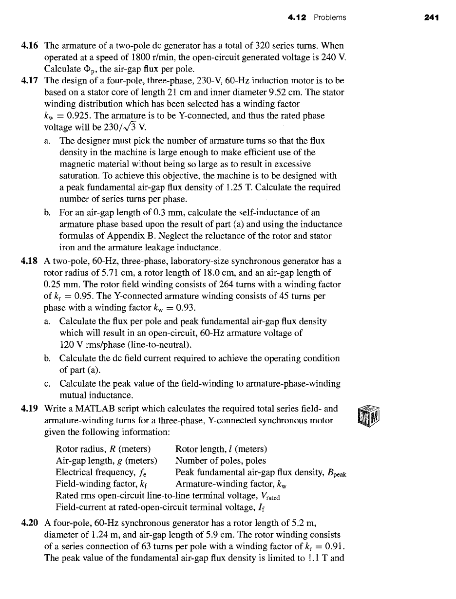
4.22 Figure 4.45 shows in cross section a machine having a rotor winding f and
two identical stator windings a and b whose axes are in quadrature. The
self-inductance of each stator winding is
Laa
and of the rotor is Lff. The air
gap is uniform. The mutual inductance between a stator winding depends on
the angular position of the rotor and may be assumed to be of the form
Maf --
M cos 00
Mbf =
M sin 00
where M is the maximum value of the mutual inductance. The resistance of
each stator winding is Ra.
a. Derive a general expression for the torque T in terms of the angle 00, the
inductance parameters, and the instantaneous currents ia, Ib, and if. Does
this expression apply at standstill? When the rotor is revolving?
b. Suppose the rotor is stationary and constant direct currents la = I0,
Ib = I0, and If = 210 are supplied to the windings in the directions
indicated by the dots and crosses in Fig. 4.45. If the rotor is allowed to
move, will it rotate continuously or will it tend to come to rest? If the
latter, at what value of 00 ?
Figure 4.45
Elementary
cylindrical-rotor, two-phase
synchronous machine for
Problem 4.22.
4.12 Problems
243
c. The rotor winding is now excited by a constant direct current If while the
stator windings carry balanced two-phase currents
ia --- ~/21a COS cot ib ---- ~/21a sin cot
The rotor is revolving at synchronous speed so that its instantaneous
angular position is given by 00 =
cot - 3,
where ~ is a phase angle
describing the position of the rotor at t = 0. The machine is an elementary
two-phase synchronous machine. Derive an expression for the torque
under these conditions.
d. Under the conditions of part (c), derive an expression for the
instantaneous terminal voltages of stator phases a and b.
4.23 Consider the two-phase synchronous machine of Problem 4.22. Derive an
expression for the torque acting on the rotor if the rotor is rotating at constant
angular velocity, such that 00 = cot + 3, and the phase currents become
unbalanced such that
ia "-- ~/~Ia cos cot ib = ~/2(Ia + I')sin
cot
What are the instantaneous and time-averaged torque under this condition?
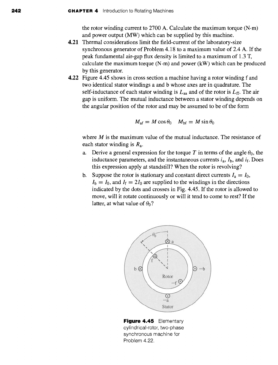
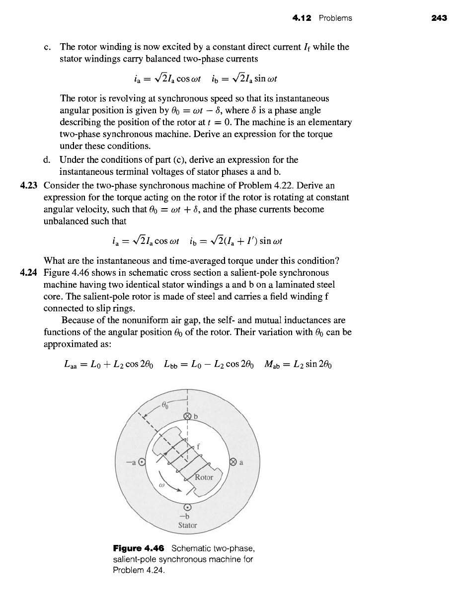
4.24 Figure 4.46 shows in schematic cross section a salient-pole synchronous
machine having two identical stator windings a and b on a laminated steel
core. The salient-pole rotor is made of steel and carries a field winding f
connected to slip rings.
Because of the nonuniform air gap, the self- and mutual inductances are
functions of the angular position 00 of the rotor. Their variation with 00 can be
approximated as:
Laa -- L0 -F L2 cos 200 Lbb = L0 -- L2 cos 200 Mab = L2 sin 200
Figure 4.46
Schematic two-phase,
salient-pole synchronous machine for
Problem 4.24.
244 CHAPTER 4 Introduction to Rotating Machines
where Lo and
L2 are
positive constants. The mutual inductance between the
rotor and the stator windings are functions of 00
Maf =
M cos 00
Mbf =
M sin 00
where M is also a positive constant. The self-inductance of the field winding,
Lff, is constant, independent of 00.
Consider the operating condition in which the field winding is excited by
direct current If and the stator windings are connected to a balanced
two-phase voltage source of frequency co. With the rotor revolving at
synchronous speed, its angular position will be given by 00 = cot.
Under this operating condition, the stator currents will be of the form
ia -- ~/21a COS (cot + 3) ib = ~/2Ia sin (cot + 6)
a. Derive an expression for the electromagnetic torque acting on the rotor.
b. Can the machine be operated as a motor and/or a generator? Explain.
c. Will the machine continue to run if the field current If is reduced to zero?
Support you answer with an expression for the torque and an explanation as
to why such operation is or is not possible.
4.25 A three-phase linear ac motor has an armature winding of wavelength 25 cm.
A three-phase balanced set of currents at a frequency of 100 Hz is applied to
the armature.
a. Calculate the linear velocity of the armature mmf wave.
b. For the case of a synchronous rotor, calculate the linear velocity of the
rotor.
c. For the case of an induction motor operating at a slip of 0.045, calculate
the linear velocity of the rotor.
4.26 The linear-motor armature of Problem 4.25 has a total active length of
7 wavelengths, with a total of 280 turns per phase with a winding factor
kw = 0.91. For an air-gap length of 0.93 cm, calculate the rms magnitude of
the balanced three-phase currents which must be supplied to the armature to
achieve a peak space-fundamental air-gap flux density of 1.45 T.
4.27 A two-phase linear permanent-magnet synchronous motor has an air-gap of
length 1.0 mm, a wavelength of 12 cm, and a pole width of 4 cm. The rotor is
5 wavelengths in length. The permanent magnets on the rotor are arranged to
produce an air-gap magnetic flux distribution that is uniform over the width
of a pole but which varies sinusoidally in space in the direction of rotor travel.
The peak density of this air-gap flux is 0.97 T.
a. Calculate the net flux per pole.
b. Each armature phase consists of 10 turns per pole, with all the poles
connected in series. Assuming that the armature winding extends many
wavelengths past either end of the rotor, calculate the peak flux linkages
of the armature winding.
c. If the rotor is traveling at a speed of 6.3 m/sec, calculate the rms voltage
induced in the armature winding.
CHAPT =R
Synchronous Machines
A
s we have seen in Section 4.2.1, a synchronous machine is an ac machine
whose speed under steady-state conditions is proportional to the frequency
of the current in its armature. The rotor, along with the magnetic field created
by the dc field current on the rotor, rotates at the same speed as, or in synchronism
with, the rotating magnetic field produced by the armature currents, and a steady
torque results. An elementary picture of how a synchronous machi,e wurk~ i~ given
in Section 4.2.1 with emphasis on torque production in terms of the interactions
between the machine's magnetic fields.
Analytical methods of examining the steady-state performance of polyphase
synchronous machines will be developed in this chapter. Initial consideration will
be given to cylindrical-rotor machines; the effects of salient poles are taken up in
Sections 5.6 and 5.7.
5.1 INTRODUCTION TO POLYPHASE
SYNCHRONOUS MACHINES
As indicated in Section 4.2.1, a synchronous machine is one in which alternating
current flows in the armature winding, and dc excitation is supplied to the field
winding. The armature winding is almost invariably on the stator and is usually a
three-phase winding, as discussed in Chapter 4. The field winding is on the rotor.
The cylindrical-rotor construction shown in Figs. 4.10 and 4.11 is used for two-
and four-pole turbine generators. The salient-pole construction shown in Fig. 4.9 is
best adapted to multipolar, slow-speed, hydroelectric generators and to most syn-
chronous motors. The dc power required for excitation--approximately one to a
few percent of the rating of the synchronous machinemis supplied by the
excitation
system.
In older machines, the excitation current was typically supplied through
slip
rings
from a dc machine, referred to as the
exciter,
which was often mounted on the
same shaft as the synchronous machine. In more modern systems, the excitation is
245