Fitzgerald A.E. Electric Machinery
Подождите немного. Документ загружается.

246 CHAPTER 5 Synchronous Machines
supplied from ac exciters and solid-state rectifiers (either simple diode bridges or
phase-controlled rectifiers). In some cases, the rectification occurs in the stationary
frame, and the rectified excitation current is fed to the rotor via slip tings. In other
systems, referred to as brushless excitation systems, the alternator of the ac exciter
is on the rotor, as is the rectification system, and the current is supplied directly to
the field-winding without the need for slip tings. One such system is described in
Appendix D.
As is discussed in Chapter 4, a single synchronous generator supplying power
to an impedance load acts as a voltage source whose frequency is determined by
the speed of its mechanical drive (or prime mover), as can be seen from Eq. 4.2.
From Eqs. 4.42, 4.44, and 4.50, the amplitude of the generated voltage is propor-
tional to the frequency and the field current. The current and power factor are then
determined by the generator field excitation and the impedance of the generator
and load.
Synchronous generators can be readily operated in parallel, and, in fact, the
electricity supply systems of industrialized countries typically have scores or even
hundreds of them operating in parallel, interconnected by thousands of miles of
transmission lines, and supplying electric energy to loads scattered over areas of many
thousands of square miles. These huge systems have grown in spite of the necessity for
designing the system so that synchronism is maintained following disturbances and
the problems, both technical and administrative, which must be solved to coordinate
the operation of such a complex system of machines and personnel. The principal
reasons for these interconnected systems are reliability of service and economies in
plant investment and operating costs.
When a synchronous generator is connected to a large interconnected system
containing many other synchronous generators, the voltage and frequency at its ar-
mature terminals are substantially fixed by the system. As a result, armature currents
will produce a component of the air-gap magnetic field which rotates at synchronous
speed (Eq. 4.41) as determined by the system electrical frequency fe. As is discussed
in Chapter 4, for the production of a steady, unidirectional electromechanical torque,
the fields of the stator and rotor must rotate at the same speed, and therefore the
rotor must turn at precisely synchronous speed. Because any individual generator
is a small fraction of the total system generation, it cannot significantly affect the
system voltage or frequency. It is thus often useful, when studying the behavior of
an individual generator or group of generators, to represent the remainder of the sys-
tem as a constant-frequency, constant-voltage source, commonly referred to as an
infinite bus.
Many important features of synchronous-machine behavior can be understood
from the analysis of a single machine connected to an infinite bus. The steady-state
behavior of a synchronous machine can be visualized in terms of the torque equa-
tion. From Eq. 4.81, with changes in notation appropriate to synchronous-machine
theory,
rr p es
T = -~
~RFfSin~RF
(5.1)
5,1 Introduction to Polyphase Synchronous Machines 247
where
(I) R
--
resultant air-gap flux per pole
Ff = mmf of the dc field winding
~RF = electrical phase angle between magnetic axes of
(I) R
and Ff
The minus sign of Eq. 4.81 has been omitted with the understanding that the
electromechanical torque acts in the direction to bring the interacting fields into
alignment. In normal steady-state operation, the electromechanical torque balances
the mechanical torque applied to the shaft. In a generator, the prime-mover torque
acts in the direction of rotation of the rotor, pushing the rotor mmf wave ahead of
the resultant air-gap flux. The electromechanical torque then opposes rotation. The
opposite situation exists in a synchronous motor, where the electromechanical torque
is in the direction of rotation, in opposition to the retarding torque of the mechanical
load on the shaft.
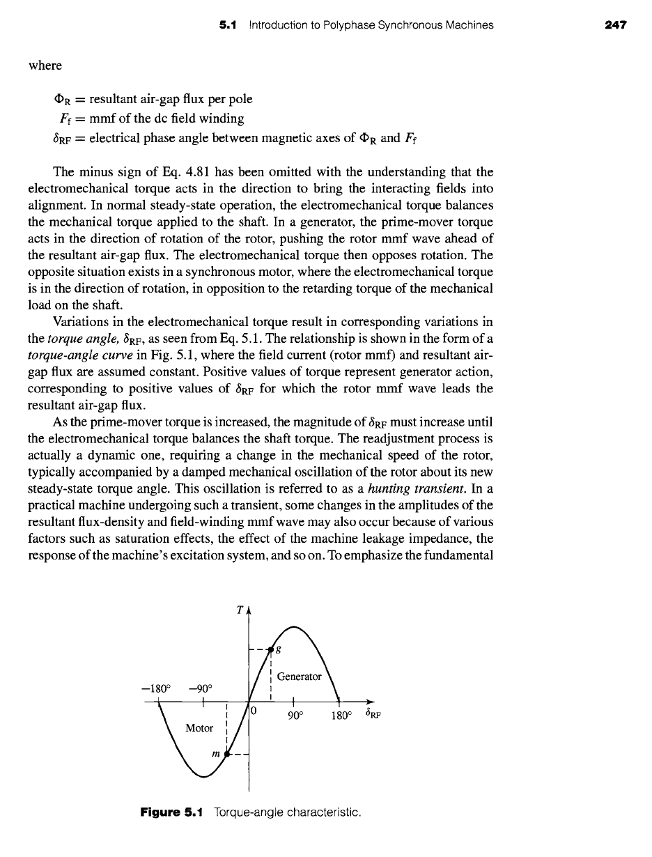
Variations in the electromechanical torque result in corresponding variations in
the
torque angle,
~RF, as seen from Eq. 5.1. The relationship is shown in the form of a
torque-angle curve
in Fig. 5.1, where the field current (rotor mmf) and resultant air-
gap flux are assumed constant. Positive values of torque represent generator action,
corresponding to positive values of ~RF for which the rotor mmf wave leads the
resultant air-gap flux.
As the prime-mover torque is increased, the magnitude of ~RF must increase until
the electromechanical torque balances the shaft torque. The readjustment process is
actually a dynamic one, requiting a change in the mechanical speed of the rotor,
typically accompanied by a damped mechanical oscillation of the rotor about its new
steady-state torque angle. This oscillation is referred to as a
hunting transient.
In a
practical machine undergoing such a transient, some changes in the amplitudes of the
resultant flux-density and field-winding mmf wave may also occur because of various
factors such as saturation effects, the effect of the machine leakage impedance, the
response of the machine's excitation system, and so on. To emphasize the fundamental
T
--180 °
\ I -.v 90 ° 180 ° ~RF
Figure 5.1
Torque-angle characteristic.
248 CHAPTER 5 Synchronous Machines
principles of synchronous-machine operation, such effects will be neglected in the
present discussion.
The adjustment of the rotor to its new angular position following a load change
can be observed experimentally in the laboratory by viewing the machine rotor with
stroboscopic light triggered from the applied armature voltage (thus having a flashing
frequency which causes the rotor to appear stationary when it is turning at its normal
synchronous speed). Alternatively, electronic sensors can be used to determine the
shaft position relative to the synchronous reference frame associated with the stator
voltage. The resultant signal can be displayed on an oscilloscope or recorded with a
data-acquisition system.
As can be seen from Fig. 5.1, an increase in prime-mover torque will result
in a corresponding increase in the torque angle. When
~RF
becomes 90 °, the elec-
tromechanical torque reaches its maximum value, known as the pull-out torque. Any
further increase in prime-mover torque cannot be balanced by a corresponding in-
crease in synchronous electromechanical torque, with the result that synchronism will
no longer be maintained and the rotor will speed up. This phenomenon is known as
loss of synchronism or pulling out of step. Under these conditions, the generator is
usually disconnected from the external electrical system by the automatic operation
of circuit breakers, and the prime mover is quickly shut down to prevent dangerous
overspeed. Note from Eq. 5.1 that the value of the pull-out torque can be increased by
increasing either the field current or the resultant air-gap flux. However, this cannot be
done without limit; the field current is limited by the ability to cool the field winding,
and the air-gap flux is limited by saturation of the machine iron.
As seen from Fig. 5.1, a similar situation occurs in a synchronous motor for which
an increase in the shaft load torque beyond the pull-out torque will cause the rotor to
lose synchronism and thus to slow down. Since a synchronous motor develops torque
only at synchronous speed, it cannot be started simply by the application of armature
voltages of rated frequency. In some cases, a squirrel-cage structure is included in
the rotor, and the motor can be started as an induction motor and then synchronized
when it is close to synchronous speed.
5.2
SYNCHRONOUS-MACHINE
INDUCTANCES; EQUIVALENT CIRCUITS
In Section 5.1, synchronous-machine torque-angle characteristics are described in
terms of the interacting air-gap flux and mmf waves. Our purpose now is to de-
rive an equivalent circuit which represents the steady-state terminal volt-ampere
characteristics.
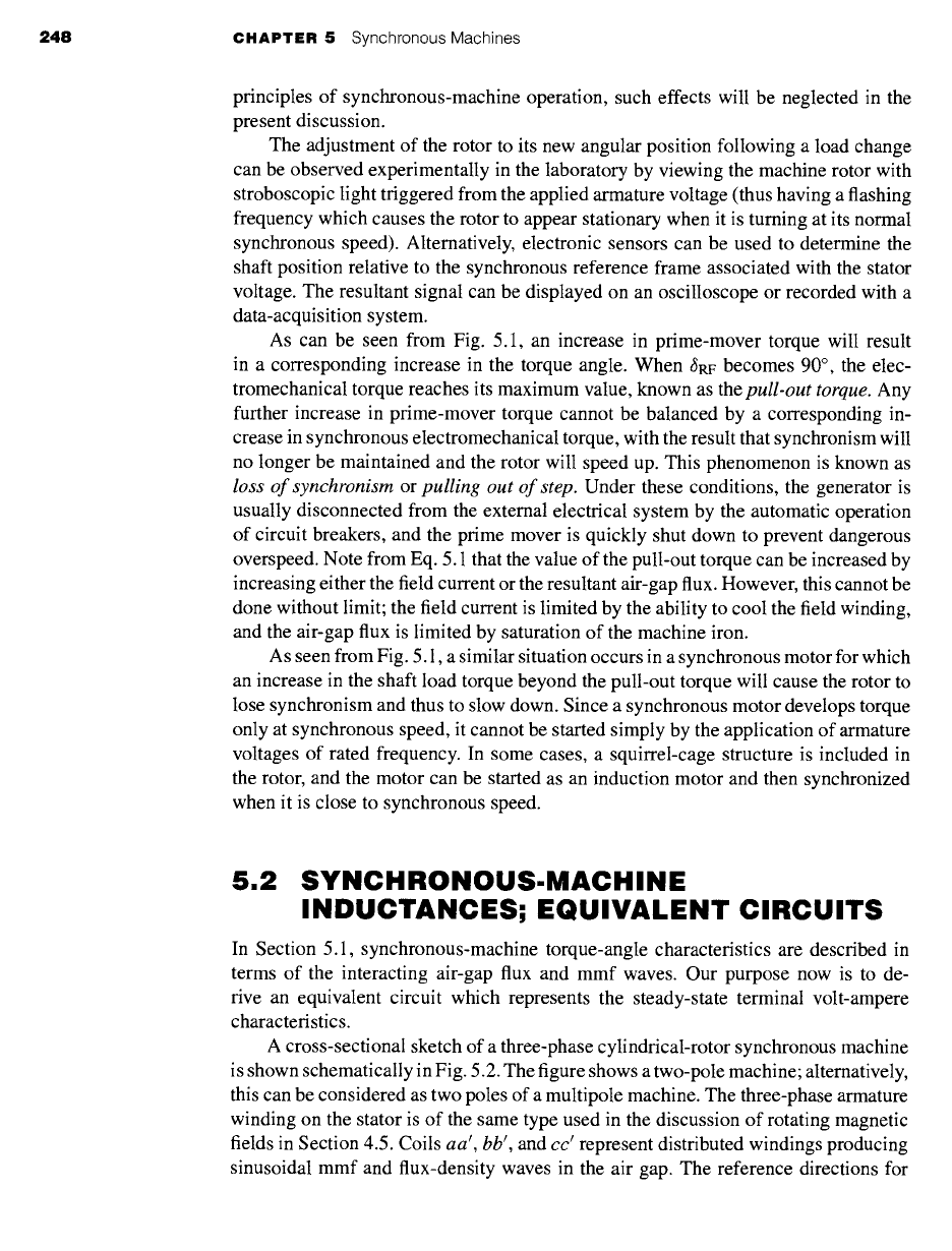
A cross-sectional sketch of a three-phase cylindrical-rotor synchronous machine
is shown schematically in Fig. 5.2. The figure shows a two-pole machine; alternatively,
this can be considered as two poles of a multipole machine. The three-phase armature
winding on the stator is of the same type used in the discussion of rotating magnetic
fields in Section 4.5. Coils aa', bb', and cc I represent distributed windings producing
sinusoidal mmf and flux-density waves in the air gap. The reference directions for
5.2
Synchronous-Machine Inductances; Equivalent Circuits 249
-~-U a
Magnetic axis
i a of rotor
c cot + 0 o
1\ f'~J2 ] Magnetic axis
~c/ ofphasea
I
--U a
Figure 5.2
Schematic diagram of
a two-pole, three-phase cylindrical-
rotor synchronous machine.
the currents are shown by dots and crosses. The field winding
ff'
on the rotor also
represents a distributed winding which produces a sinusoidal mmf and flux-density
wave centered on its magnetic axis and rotating with the rotor.
When the flux linkages with armature phases a, b, c and field winding f are ex-
pressed in terms of the inductances and currents as follows,
'ka = £aaia -Jr- Eabib q-" £acic "k- £afif (5.2)
)~b = £baia -+- £bbib -+- /2bcic "k- /2bfif (5.3)
)~c = /2caia q- /2cbib q- /2ccic + /2cfif (5.4)
~-f ~--- /2faia + /2fbib q- /2fcic + /2ffif (5.5)
the induced voltages can be found from Faraday's law. Here, two like subscripts denote
a self-inductance, and two unlike subscripts denote a mutual inductance between the
two windings. The script 12 is used to indicate that, in general, both the self- and
mutual inductances of a three-phase machine may vary with rotor angle, as is seen,
for example, in Section C.2, where the effects of salient poles are analyzed.
Before we proceed, it is useful to investigate the nature of the various inductances.
Each of these inductances can be expressed in terms of constants which can be
computed from design data or measured by tests on an existing machine.
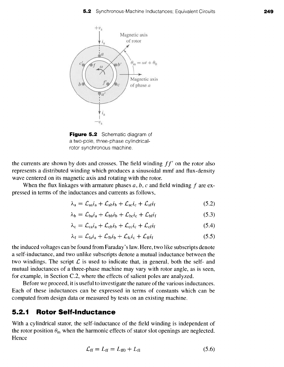
5.2.1 Rotor Self-Inductance
With a cylindrical stator, the self-inductance of the field winding is independent of
the rotor position 0m when the harmonic effects of stator slot openings are neglected.
Hence
/2ff = Lff = Lff0 + Lfl (5.6)
250 CHAPTER
5 Synchronous Machines
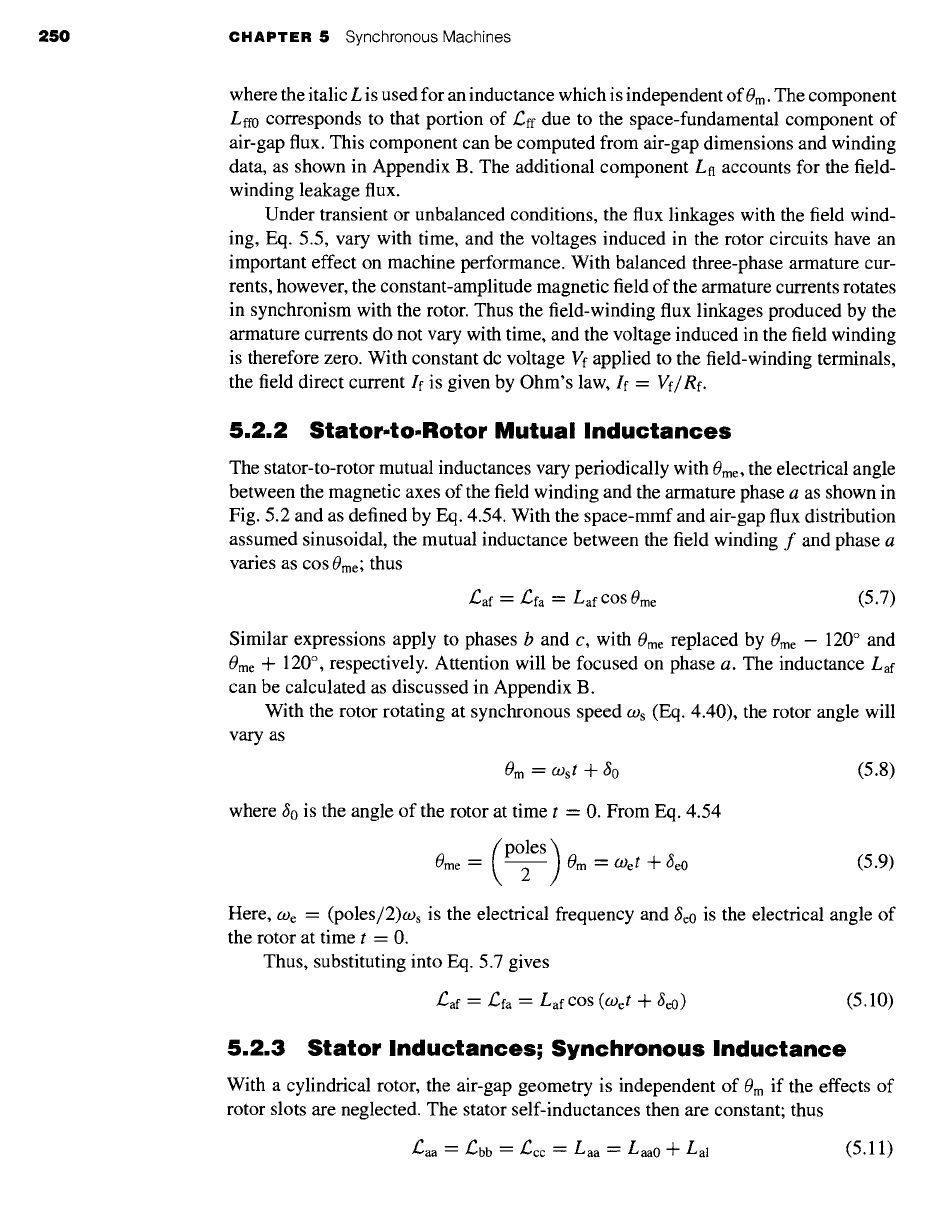
where the italic L is used for an inductance which is independent of 0m. The component
Lff0 corresponds to that portion of/2ff due to the space-fundamental component of
air-gap flux. This component can be computed from air-gap dimensions and winding
data, as shown in Appendix B. The additional component Ln accounts for the field-
winding leakage flux.
Under transient or unbalanced conditions, the flux linkages with the field wind-
ing, Eq. 5.5, vary with time, and the voltages induced in the rotor circuits have an
important effect on machine performance. With balanced three-phase armature cur-
rents, however, the constant-amplitude magnetic field of the armature currents rotates
in synchronism with the rotor. Thus the field-winding flux linkages produced by the
armature currents do not vary with time, and the voltage induced in the field winding
is therefore zero. With constant dc voltage Vf applied to the field-winding terminals,
the field direct current If is given by Ohm's law, If =
Vf/Re.
5.2.2 Stator-to-Rotor Mutual Inductances
The stator-to-rotor mutual inductances vary periodically with
0me,
the electrical angle
between the magnetic axes of the field winding and the armature phase a as shown in
Fig. 5.2 and as defined by Eq. 4.54. With the space-mmf and air-gap flux distribution
assumed sinusoidal, the mutual inductance between the field winding f and phase a
varies as
cos 0me;
thus
~af : /~fa -- Laf cos 0me
(5.7)
Similar expressions apply to phases b and c, with
0me
replaced by 0me - 120 ° and
0me
-~- 120 °, respectively. Attention will be focused on phase a. The inductance
Laf
can be calculated as discussed in Appendix B.
With the rotor rotating at synchronous speed Ws (Eq. 4.40), the rotor angle will
vary as
0,, = Wst + ~o
(5.8)
where 60 is the angle of the rotor at time t = 0. From Eq. 4.54
0me
(poles)
= 2 0m -- Oget -q- •e0
(5.9)
Here,
O) e ~---
(poles/2)Ws is the electrical frequency and ~e0 is the electrical angle of
the rotor at time t - 0.
Thus, substituting into Eq. 5.7 gives
£~af = /~fa -- LafcOs (Oget + ~e0)
(5.10)
5.2.3 Stator Inductances; Synchronous Inductance
With a cylindrical rotor, the air-gap geometry is independent of
0m
if the effects of
rotor slots are neglected. The stator self-inductances then are constant; thus
/:aa -- /:bb = /~cc = Laa -" Laao + Lal
(5.11)
6.9 Problems 351
has a wound rotor whose terminals are brought out through slip rings.
a. At what speed does the motor run?
b. What is the frequency of the voltages produced at the slip rings of the
induction motor?
c. What will be the frequency of the voltages produced at the slip rings of
the induction motor if two leads of the induction-motor stator are
interchanged, reversing the direction of rotation of the resultant rotating
field?
6.9 A three-phase, eight-pole, 60-Hz, 4160-V, 1000-kW squirrel-cage induction
motor has the following equivalent-circuit parameters in ohms per phase Y
referred to the stator:
R1 =0.220 R2=0.207 X1 =1.95 X2=2.42 Xm=45.7
Determine the changes in these constants which will result from the following
proposed design modifications. Consider each modification separately.
a. Replace the stator winding with an otherwise identical winding with a
wire size whose cross-sectional area is increased by 4 percent.
b. Decrease the inner diameter of the stator laminations such that the air gap
is decreased by 15 percent.
c. Replace the aluminum rotor bars (conductivity 3.5 x 10⁷ mhos/m) with
copper bars (conductivity 5.8 x 10⁷ mhos/m).
d. Reconnect the stator winding, originally connected in Y for 4160-V
operation, in A for 2.4 kV operation.
6.10 A three-phase, Y-connected, 460-V (line-line), 25-kW, 60-Hz, four-pole
induction motor has the following equivalent-circuit parameters in ohms per
phase referred to the stator:
R1 = 0.103 R2 = 0.225 X1 = 1.10 X2 = 1.13
Xm =
59.4
The total friction and windage losses may be assumed constant at 265 W, and
the core loss may be assumed to be equal to 220 W. With the motor
connected directly to a 460-V source, compute the speed, output shaft torque
and power, input power and power factor and efficiency for slips of 1, 2 and
3 percent. You may choose either to represent the core loss by a resistance
connected directly across the motor terminals or by resistance Rc connected
in parallel with the magnetizing reactance
Xm.
6.11 Consider the induction motor of Problem 6.10.
a. Find the motor speed in r/min corresponding to the rated shaft output
power of 25 kW. (Hint: This can be easily done by writing a MATLAB
script which searches over the motor slip.)
b. Similarly, find the speed in r/min at which the motor will operate with
no external shaft load (assuming the motor load at that speed to consist
only of the friction and windage losses).
c. Write a MATLAB script to plot motor efficiency versus output power as
the motor output power varies from zero to full load.
252 CHAPTER 5 Synchronous Machines
air-gap component of the phase-a self-flux linkages. The second,
Lal,
known as the
armature-winding
leakage inductance,
is due to the leakage component of phase-a
1
flux linkages. The third component, ~
Laa0,
is due to the phase-a flux linkages from
the space-fundamental component of air-gap flux produced by currents in phases b
and c. Under balanced three-phase conditions, the phase-b and -c currents are related
to the current in phase a by Eq. 5.15. Thus the synchronous inductance is an apparent
inductance in that it accounts for the flux linkages of phase a in terms of the current
in phase a, even though some of this flux linkage is due to currents in phases a and b.
Hence, although synchronous inductance appears in that role in Eq. 5.18, it is not the
self-inductance of phase a alone.
The significance of the synchronous inductance can be further appreciated with
reference to the discussion of rotating magnetic fields in Section 4.5.2, where it
was shown that under balanced three-phase conditions, the armature currents create a
rotating magnetic flux wave in the air gap of magnitude equal to 3 times the magnitude
of that due to phase a alone, the additional component being due to the phase-b and
-c currents. This corresponds directly to the
3 Laa0
component of the synchronous
inductance in Eq. 5.17; this component of the synchronous inductance accounts for
the total space-fundamental air-gap component of phase-a flux linkages produced by
the three armature currents under balanced three-phase conditions.
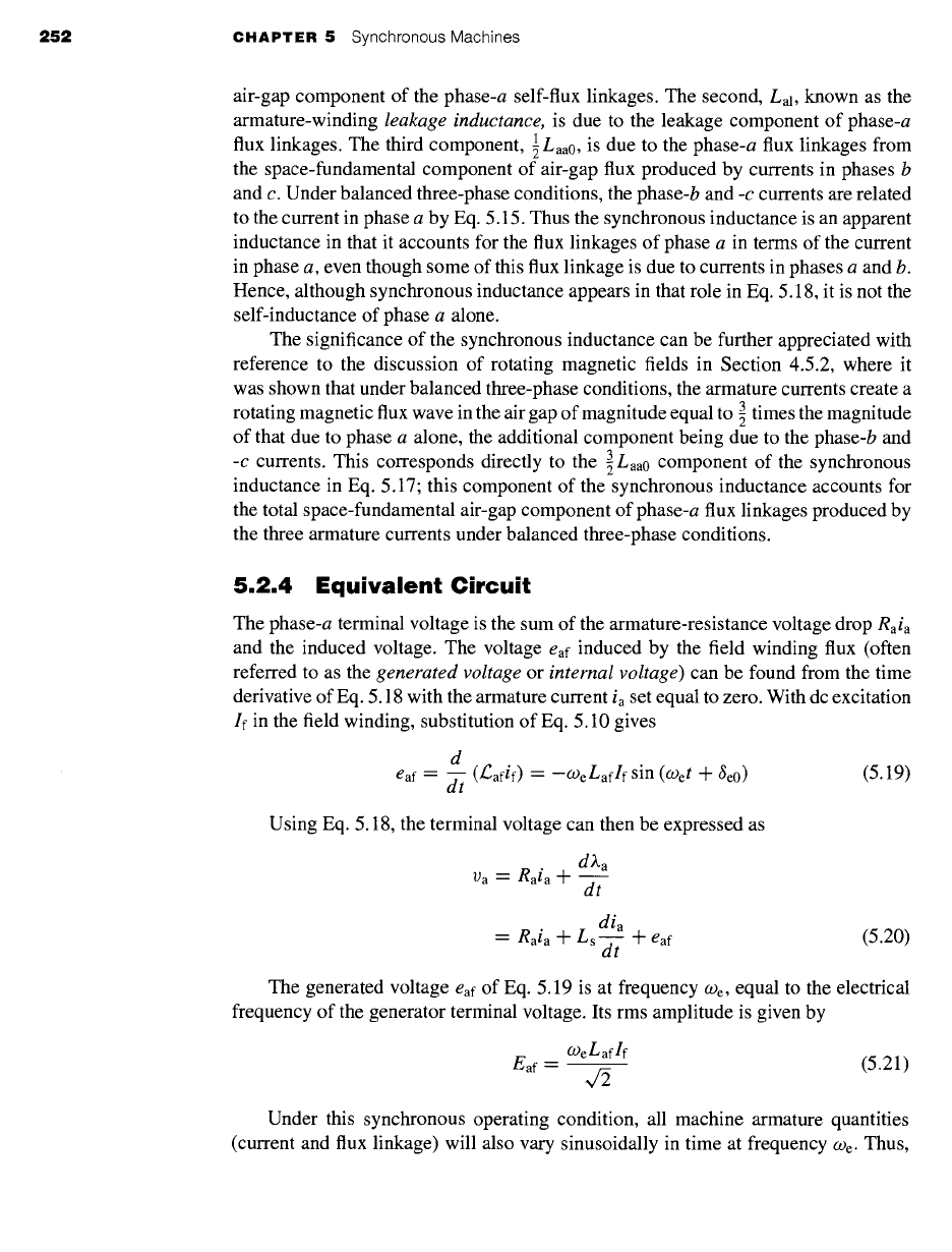
5.2.4 Equivalent Circuit
The phase-a terminal voltage is the sum of the armature-resistance voltage drop
Raia
and the induced voltage. The voltage eaf induced by the field winding flux (often
referred to as the
generated voltage
or
internal voltage)
can be found from the time
derivative of Eq. 5.18 with the armature current ia set equal to zero. With dc excitation
If in the field winding, substitution of Eq. 5.10 gives
d
eaf -- ~-~ (/~afif) -- -o)eLaflf sin (Wet + 6e0) (5.19)
Using Eq. 5.18, the terminal voltage can then be expressed as
d~.a
Va = Raia -Jr"
dt
dia
= Raia -Jr- Ls--d- f +
eaf (5.20)
The generated voltage eaf of Eq. 5.19 is at frequency We, equal to the electrical
frequency of the generator terminal voltage. Its rms amplitude is given by
o&Laflf
Eaf -----
(5.21)
Under this synchronous operating condition, all machine armature quantifies
(current and flux linkage) will also vary sinusoidally in time at frequency We. Thus,
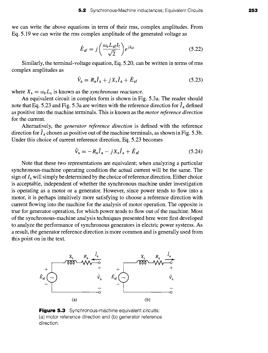
5,2 Synchronous-Machine Inductances; Equivalent Circuits 253
we can write the above equations in term of their rms, complex amplitudes. From
Eq. 5.19 we can write the rms complex amplitude of the generated voltage as
(°)eLaflf)eJSe°
(5.22)
J~af =
j
Similarly, the terminal-voltage equation, Eq. 5.20, can be written in terms of rms
complex amplitudes as
ga -- eala -4-
j Xsla
-+-/~af
(5.23)
where Xs
-- (De ts
is known as the
synchronous reactance.
An equivalent circuit in complex form is shown in Fig. 5.3a. The reader should
note that Eq. 5.23 and Fig. 5.3a are written with the reference direction
for Ia
defined
as positive into the machine terminals. This is known as the
motor reference direction
for the current.
Alternatively, the
generator reference direction
is defined with the reference
direction for
Ia
chosen as positive out of the machine terminals, as shown in Fig. 5.3b.
Under this choice of current reference direction, Eq. 5.23 becomes
Va-- -gala-
jXsla
+
Eaf
(5.24)
Note that these two representations are equivalent; when analyzing a particular
synchronous-machine operating condition the actual current will be the same. The
sign of Ia will simply be determined by the choice of reference direction. Either choice
is acceptable, independent of whether the synchronous machine under investigation
is operating as a motor or a generator. However, since power tends to flow into a
motor, it is perhaps intuitively more satisfying to choose a reference direction with
current flowing into the machine for the analysis of motor operation. The opposite is
true for generator operation, for which power tends to flow out of the machine. Most
of the synchronous-machine analysis techniques presented here were first developed
to analyze the performance of synchronous generators in electric power systems. As
a result, the generator reference direction is more common and is generally used from
this point on in the text.
Xs Ra Ia
,vov,-.y~,:~
+ + +
" ~7 a "
Ea -o Ea
(a) (b)
Xs Ra Ia
~ o
+
Figure 5.3 Synchronous-machine equivalent circuits:
(a) motor reference direction and (b) generator reference
direction.
~a
254 CHAPTER 5 Synchronous Machines
+
X~0 Xal R a
+
#R
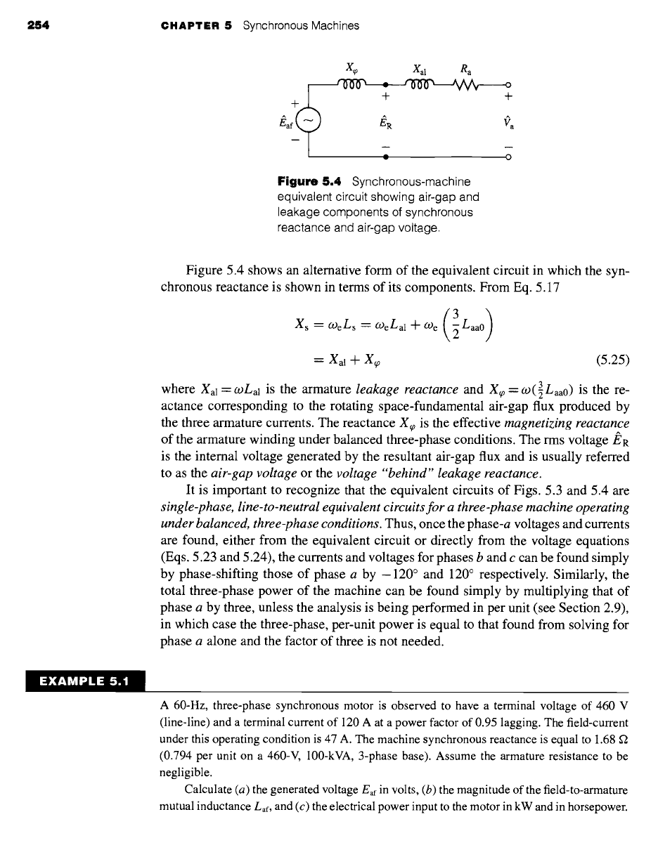
Figure 5.4
Synchronous-machine
equivalent circuit showing air-gap and
leakage components of synchronous
reactance and air-gap voltage.
Figure 5.4 shows an alternative form of the equivalent circuit in which the syn-
chronous reactance is shown in terms of its components. From Eq. 5.17
(3)
Xs = (-oeLs = (-oeLal + (-Oe ~ Laa0
= Xal "l- Xq)
(5.25)
where Xal
=coLal
is the armature
leakage reactance
and X~0 = (-o(3Laa0) is the re-
actance corresponding to the rotating space-fundamental air-gap flux produced by
the three armature currents. The reactance X~0 is the effective
magnetizing reactance
of the armature winding under balanced three-phase conditions. The rms voltage/~R
is the internal voltage generated by the resultant air-gap flux and is usually referred
to as the
air-gap voltage
or the
voltage "behind" leakage reactance.
It is important to recognize that the equivalent circuits of Figs. 5.3 and 5.4 are
single-phase, line-to-neutral equivalent circuits for a three-phase machine operating
under balanced, three-phase conditions.
Thus, once the phase-a voltages and currents
are found, either from the equivalent circuit or directly from the voltage equations
(Eqs. 5.23 and 5.24), the currents and voltages for phases b and c can be found simply
by phase-shifting those of phase a by -120 ° and 120 ° respectively. Similarly, the
total three-phase power of the machine can be found simply by multiplying that of
phase a by three, unless the analysis is being performed in per unit (see Section 2.9),
in which case the three-phase, per-unit power is equal to that found from solving for
phase a alone and the factor of three is not needed.
EXAMPLE 5.
A 60-Hz, three-phase synchronous motor is observed to have a terminal voltage of 460 V
(line-line) and a terminal current of 120 A at a power factor of 0.95 lagging. The field-current
under this operating condition is 47 A. The machine synchronous reactance is equal to 1.68 ~2
(0.794 per unit on a 460-V, 100-kVA, 3-phase base). Assume the armature resistance to be
negligible.
Calculate (a) the generated voltage
Eaf
in volts, (b) the magnitude of the field-to-armature
mutual inductance Laf, and (c) the electrical power input to the motor in kW and in horsepower.
5.2 Synchronous-Machine Inductances; Equivalent Circuits 255
II
Solution
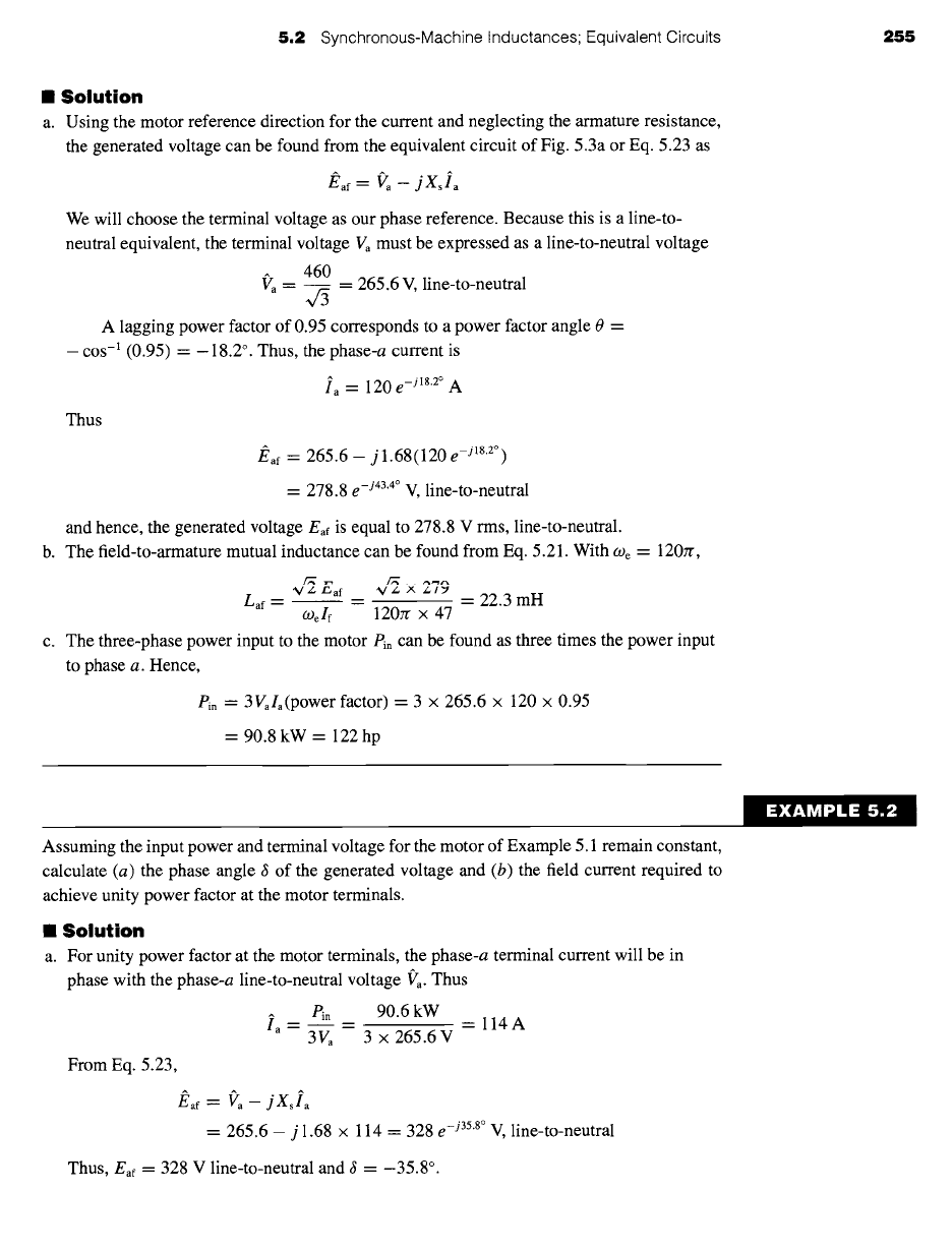
a. Using the motor reference direction for the current and neglecting the armature resistance,
the generated voltage can be found from the equivalent circuit of Fig. 5.3a or Eq. 5.23 as
/~af = Va -- jXsla
We will choose the terminal voltage as our phase reference. Because this is a line-to-
neutral equivalent, the terminal voltage Va must be expressed as a line-to-neutral voltage
f'a-
460
= 265.6 V, line-to-neutral
A lagging power factor of 0.95 corresponds to a power factor angle 0 =
- cos -I (0.95) = - 18.2 °. Thus, the phase-a current is
Ia = 120 e -j18"2° A
Thus
J~af ---
265.6 - j 1.68(120
e -j18"2°)
= 278.8
e -j43"4° V,
line-to-neutral
and hence, the generated voltage
Eaf
is equal to 278.8 V rms, line-to-neutral.
b. The field-to-armature mutual inductance can be found from Eq. 5.21. With
(_D e --
120rr,
"V/-., F-.,af %//_., ,,x,
/_.1~,
Lay
= = "--
22.3 mH
o) e If
120zr x 47
c. The three-phase power input to the motor
Pin can
be found as three times the power input
to phase a. Hence,
Pin -'-
3Vala(power factor) = 3 x 265.6 × 120 x 0.95
= 90.8 kW = 122 hp
Assuming the input power and terminal voltage for the motor of Example 5.1 remain constant,
calculate (a) the phase angle 8 of the generated voltage and (b) the field current required to
achieve unity power factor at the motor terminals.
II Solution
a. For unity power factor at the motor terminals, the phase-a terminal current will be in
phase with the phase-a line-to-neutral voltage f'a. Thus
Pin __
90.6 kW = 114 A
Ia =
3Va
--
3 x 265.6 V
From Eq. 5.23,
Eaf'- Va - jXsla
= 265.6 - j 1.68 × 114 = 328
e -j358°
V, line-to-neutral
Thus, Eaf =
328 V line-to-neutral and 8 = -35.8 °.
EXAMPLE 5.2