Fitzgerald A.E. Electric Machinery
Подождите немного. Документ загружается.

206
CHAPTER 4 Introduction to Rotating Machines
while the positive-traveling waves reinforce
.~"+(0ae, t) = .~ "+ d- .~'~1 -+- .~'+
3
= ~ Fmax cos (0ae - O)et) (4.38)
Thus, the result of displacing the three windings by 120 ° in space phase and
displacing the winding currents by 120 ° in time phase is a single positive-traveling
mmf wave
3
• ~"(0ae, t) = ~ Fmax cos (0ae -
Wet)
=- ((poles))
3 Fmax cos 0a -
Wet
(4.39)
2 2
The air-gap mmf wave described by Eq. 4.39 is a space-fundamental sinu-
soidal function of the electrical space angle 0ae (and hence of the space angle 0a =
(2/poles)0ae). It has a constant amplitude of (3/2)Fmax, i.e., 1.5 times the amplitude
of the air-gap mmf wave produced by the individual phases alone. It has a positive
peak at angle 0a = (2/poles)wet. Thus, under balanced three-phase conditions, the
three-phase winding produces an air-gap mmf wave which rotates at
synchronous
angular velocity Ws
(2)
Ws= poles We (4.40)
where
09 e "--
angular frequency of the applied electrical excitation [rad/sec]
Ws = synchronous spatial angular velocity of the air-gap mmf wave [rad/sec]
The corresponding
synchronous speed ns
in r/min can be expressed in terms of
the applied electrical frequency fe = we/(2zr) in Hz as
(120)
ns = poles fe r/min (4.41)
In general, a rotating field of constant amplitude will be produced by a q-phase
winding excited by balanced q-phase currents of frequency fe when the respective
phase axes are located
2rr/q
electrical radians apart in space. The amplitude of this
flux wave will be
q/2
times the maximum contribution of any one phase, and the
synchronous angular velocity 2
will remain COs = (~)We radians per second.
In this section, we have seen that a polyphase winding excited by balanced
polyphase currents produces a rotating mmf wave. Production of a rotating mmf
wave and the corresponding rotating magnetic flux is key to the operation of polyphase
rotating electrical machinery. It is the interaction of this magnetic flux wave with that
of the rotor which produces torque. Constant torque is produced when rotor-produced
magnetic flux rotates in sychronism with that of the stator.
4.5 Rotating MMF Waves in AC Machines
207
4.5.3 Graphical Analysis of Polyphase MMF
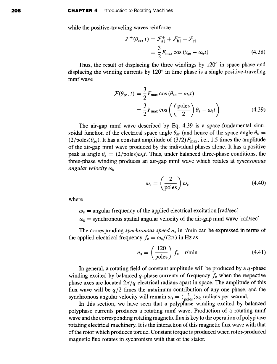
For balanced three-phase currents as given by Eqs. 4.23 to 4.25, the production of
a rotating mmf can also be shown graphically. Consider the state of affairs at t = 0
(Fig. 4.30), the moment when the phase-a current is at its maximum value Im. The mmf
of phase a then has its maximum value Fmax, as shown by the vector Fa = Fmax drawn
along the magnetic axis of phase a in the two-pole machine shown schematically in
Fig. 4.31a. At this moment, currents ib and ic are both
lm/2
in the negative direction,
as shown by the dots and crosses in Fig. 4.31 a indicating the actual instantaneous di-
rections. The corresponding mmf's of phases b and c are shown by the vectors Fb and
Fc, both of magnitude Fmax/2 drawn in the negative direction along the magnetic axes
of phases b and c, respectively. The resultant, obtained by adding the individual con-
3 Fmax centered on the axis
tributions of the three phases, is a vector of magnitude F =
of phase a. It represents a sinusoidal space wave with its positive peak centered on the
axis of phase a and having an amplitude 3 times that of the phase-a contribution alone.
At a later time COet = rr/3 (Fig. 4.30), the currents in phases a and b are a positive
half maximum, and that in phase c is a negative maximum. The individual mmf
components and their resultant are now shown in Fig. 4.3 lb. The resultant has the same
amplitude as at t = 0, but it has now rotated counterclockwise 60 electrical degrees in
space. Similarly, at COet = 2re/3 (when the phase-b current is a positive maximum and
the phase-a and phase-c currents are a negative half maximum) the same resultant mmf
distribution is again obtained, but it has rotated counterclockwise 60 electrical degrees
still farther and is now aligned with the magnetic axis of phase b (see Fig. 4.31 c). As
time passes, then, the resultant mmf wave retains its sinusoidal form and amplitude
but rotates progressively around the air gap; the net result can be seen to be an mmf
wave of constant amplitude rotating at a uniform angular velocity.
In one cycle the resultant mmf must be back in the position of Fig. 4.3 l a. The
mmf wave therefore makes one revolution per electrical cycle in a two-pole machine.
In a multipole machine the mmf wave travels one pole-pair per electrical cycle and
hence one revolution in poles/2 electrical cycles.
~b h
F = 3_ Fmax
~b
X~F = 3
7 Fmax
3
[Fmax
--IP'- a
c c
(a) (b) (c)
Figure
4.31 The production of a rotating magnetic field by means of three-phase currents.
208 CHAPTER
4 Introduction to Rotating Machines
EXAMPLE 4.3
Consider a three-phase stator excited with balanced, 60-Hz currents. Find the synchronous
angular velocity in rad/sec and speed in r/min for stators with two, four, and six poles.
I1
Solution
For a frequency of fe = 60 Hz, the electrical angular frequency is equal to
we = 2zrfe = 120zr ~, 377 rad/sec
Using Eqs. 4.40 and 4.41, the following table can be constructed:
Poles ns (r/lnin) ~:s (rad/sec)
2 3600 1207r ~ 377
4 1800 60zc
6 1200 407r
)ractice Problem 4.:
Repeat Example 4.3 for a three-phase stator excited by balanced 50-Hz currents.
Solution
Poles n~ (r/min) ~s (rad/see)
2 3000 100Jr
4 1500 50zr
6 1000 100Jr/3
4.6 GENERATED VOLTAGE
The general nature of the induced voltage has already been discussed in Section 4.2.
Quantitative expressions for the induced voltage will now be determined.
4.6.1 AC Machines
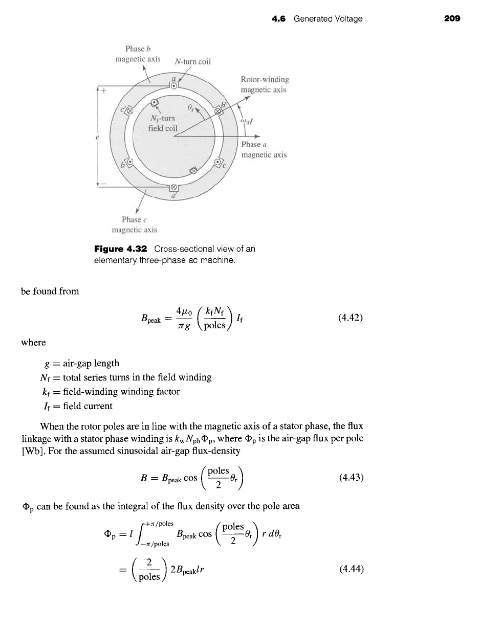
An elementary ac machine is shown in cross section in Fig. 4.32. The coils on both the
rotor and the stator have been shown as concentrated, multiple-turn, full-pitch coils.
As we have seen, a machine with distributed windings can be represented in this form
simply by multiplying the number of series turns in the winding by a winding factor.
Under the assumption of a small air gap, the field winding can be assumed to produce
radial space-fundamental air-gap flux of peak flux density Bpeak. Although Fig. 4.32
shows a two-pole machine, the analysis presented here is for the general case of a
multipole machine. As is derived in Example 4.2, if the air gap is uniform, Bpeak can
4.6 Generated Voltage 209
Phase b
magnetic axis
N-turn coil
.winding
',tic axis
a
• .tic axis
Phase c
magnetic axis
Figure 4.32
Cross-sectional view of an
elementary three-phase ac machine.
be found from
where
g = air-gap length
4.0 (
kfNf )
Bpeak --
7rg \poles If
Nf - total series turns in the field winding
kf -- field-winding winding factor
If = field current
(4.42)
poles )
B
=
Bpeak COS 2 Or (4.43)
~p can be found as the integral of the flux density over the pole area
~P i f+Jr/poles (poles)
-- Bpeak COS
Or r dOr
,J -zr/poles
2
poles) 2Bpeaklr
(4.44)
When the rotor poles are in line with the magnetic axis of a stator phase, the flux
linkage with a stator phase winding is kwNph~p, where ~p is the air-gap flux per pole
[Wb]. For the assumed sinusoidal air-gap flux-density
210 CHAPTER 4
Introduction to Rotating Machines
EXAMPLE 4.4
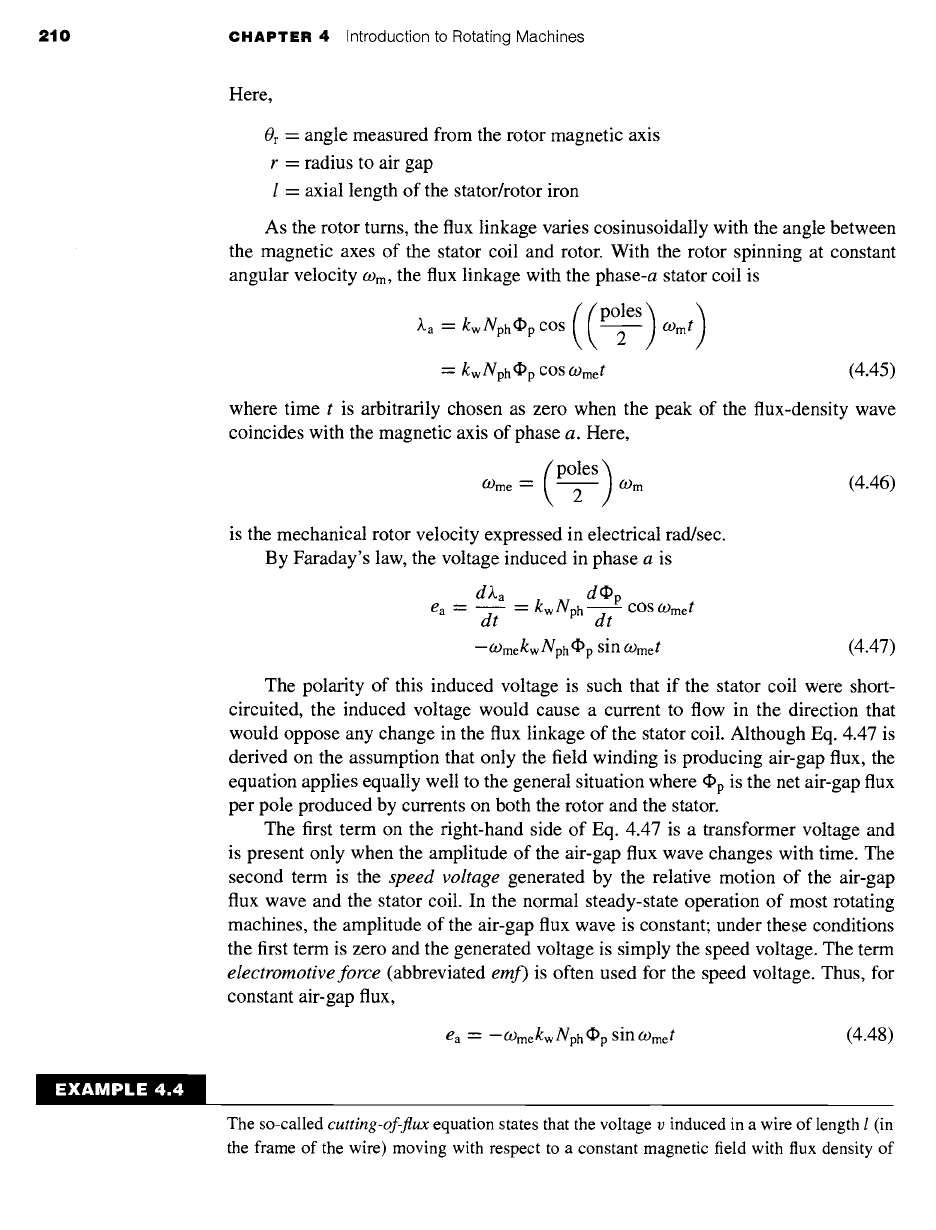
Here,
Or = angle measured from the rotor magnetic axis
r = radius to air gap
1 = axial length of the stator/rotor iron
As the rotor turns, the flux linkage varies cosinusoidally with the angle between
the magnetic axes of the stator coil and rotor. With the rotor spinning at constant
angular velocity tom, the flux linkage with the phase-a stator coil is
~a = kwNph~p COs ( (P°12eS) oJm t)
~--- kw Nph (I)p cos
COmet (4.45)
where time t is arbitrarily chosen as zero when the peak of the flux-density wave
coincides with the magnetic axis of phase a. Here,
( o,es)
COme =
2 COrn (4.46)
is the mechanical rotor velocity expressed in electrical rad/sec.
By Faraday's law, the voltage induced in phase a is
d~.a __ kwNphdC~p
ea = dt
--~ cos COmet
-COmekw Nph (I)p
sin
COmet
(4.47)
The polarity of this induced voltage is such that if the stator coil were short-
circuited, the induced voltage would cause a current to flow in the direction that
would oppose any change in the flux linkage of the stator coil. Although Eq. 4.47 is
derived on the assumption that only the field winding is producing air-gap flux, the
equation applies equally well to the general situation where
(I)p
is the net air-gap flux
per pole produced by currents on both the rotor and the stator.
The first term on the fight-hand side of Eq. 4.47 is a transformer voltage and
is present only when the amplitude of the air-gap flux wave changes with time. The
second term is the
speed voltage
generated by the relative motion of the air-gap
flux wave and the stator coil. In the normal steady-state operation of most rotating
machines, the amplitude of the air-gap flux wave is constant; under these conditions
the first term is zero and the generated voltage is simply the speed voltage. The term
electromotive force
(abbreviated
emf)
is often used for the speed voltage. Thus, for
constant air-gap flux,
ea -- -COmekw Nph (l)p
sin
COmet
(4.48)
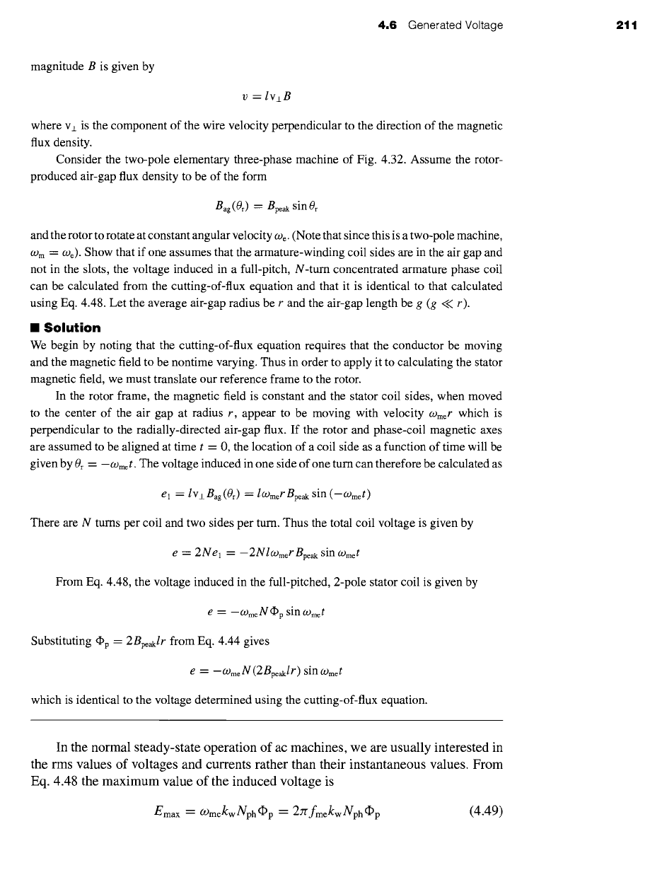
The so-called
cutting-of-flux
equation states that the voltage v induced in a wire of length I (in
the frame of the wire) moving with respect to a constant magnetic field with flux density of
4.6 Generated Voltage 2tl
magnitude B is given by
v = IvzB
where v± is the component of the wire velocity perpendicular to the direction of the magnetic
flux density.
Consider the two-pole elementary three-phase machine of Fig. 4.32. Assume the rotor-
produced air-gap flux density to be of the form
Bag(0r) ~-- Bpeak sin Or
and the rotor to rotate at constant angular velocity We. (Note that since this is a two-pole machine,
Wm -- We). Show that if one assumes that the armature-winding coil sides are in the air gap and
not in the slots, the voltage induced in a full-pitch, N-turn concentrated armature phase coil
can be calculated from the cutting-of-flux equation and that it is identical to that calculated
using Eq. 4.48. Let the average air-gap radius be r and the air-gap length be g (g << r).
am
Solution
We begin by noting that the cutting-of-flux equation requires that the conductor be moving
and the magnetic field to be nontime varying. Thus in order to apply it to calculating the stator
magnetic field, we must translate our reference frame to the rotor.
In the rotor frame, the magnetic field is constant and the stator coil sides, when moved
to the center of the air gap at radius r, appear to be moving with velocity COmer which is
perpendicular to the radially-directed air-gap flux. If the rotor and phase-coil magnetic axes
are assumed to be aligned at time t --- 0, the location of a coil side as a function of time will be
given by Or = --COmet. The voltage induced in one side of one turn can therefore be calculated as
el = lvj_
Bag
(Or) "--
lO)mer
Bpeak
sin (-COmet)
There are N turns per coil and two sides per turn. Thus the total coil voltage is given by
e = 2Nel = -2Nlwmer
Bpe~ sin COmet
From Eq. 4.48, the voltage induced in the full-pitched, 2-pole stator coil is given by
e
= -(_omeN
(I)p
sin
COme/
Substituting (I)p =
2Bpeaklr
from Eq. 4.44 gives
e
= -(.omeN
(2BpeJr)
sin COmet
which is identical to the voltage determined using the cutting-of-flux equation.
In the normal steady-state operation of ac machines, we are usually interested in
the rms values of voltages and currents rather than their instantaneous values. From
Eq. 4.48 the maximum value of the induced voltage is
Emax --- Ogmekw Nph ~p = 2~fmekw Nph ~p
(4.49)
212 CHAPTER 4 Introduction to Rotating Machines
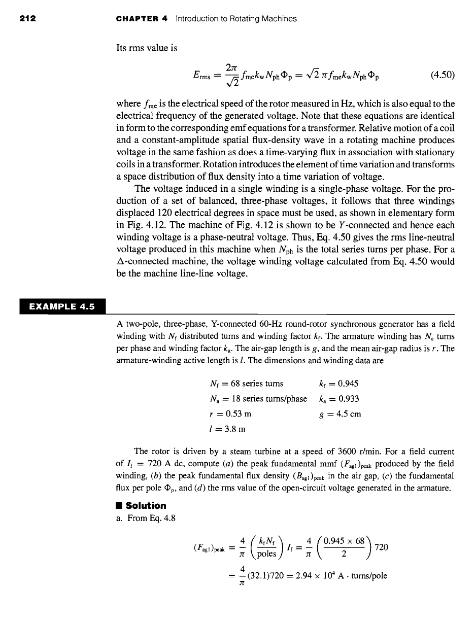
Its rms value is
2zr fm~kw
Nph ~p = ~
zrfm~kw
Nph ~p (4.50)
Erms = ~/~
where
fme
is the electrical speed of the rotor measured in Hz, which is also equal to the
electrical frequency of the generated voltage. Note that these equations are identical
in form to the corresponding emf equations for a transformer. Relative motion of a coil
and a constant-amplitude spatial flux-density wave in a rotating machine produces
voltage in the same fashion as does a time-varying flux in association with stationary
coils in a transformer. Rotation introduces the element of time variation and transforms
a space distribution of flux density into a time variation of voltage.
The voltage induced in a single winding is a single-phase voltage. For the pro-
duction of a set of balanced, three-phase voltages, it follows that three windings
displaced 120 electrical degrees in space must be used, as shown in elementary form
in Fig. 4.12. The machine of Fig. 4.12 is shown to be Y-connected and hence each
winding voltage is a phase-neutral voltage. Thus, Eq. 4.50 gives the rms line-neutral
voltage produced in this machine when Nph is the total series turns per phase. For a
A-connected machine, the voltage winding voltage calculated from Eq. 4.50 would
be the machine line-line voltage.
EXAMPLE 4.5
A two-pole, three-phase, Y-connected 60-Hz round-rotor synchronous generator has a field
winding with Nf distributed turns and winding factor kf. The armature winding has Na turns
per phase and winding factor
ka.
The air-gap length is g, and the mean air-gap radius is r. The
armature-winding active length is I. The dimensions and winding data are
Nf = 68 series turns
kf =
0.945
Na = 18 series turns/phase
ka =
0.933
r = 0.53 m g = 4.5 cm
l=3.8m
The rotor is driven by a steam turbine at a speed of 3600 r/min. For a field current
of If = 720 A dc, compute (a) the peak fundamental mmf (Fag~)p~ak produced by the field
winding, (b) the peak fundamental flux density
(Bagl)peak
in the air gap, (c) the fundamental
flux per pole ~p, and (d) the rms value of the open-circuit voltage generated in the armature.
II
Solution
a. From Eq. 4.8
4 / 4 (0945 x68)
(Fagl)peak = -- 720
7r ~ If=--
zr 2
4
= --(32.1)720 = 2.94
x 10 4
A. turns/pole
7l"
4.6
Generated Voltage 213
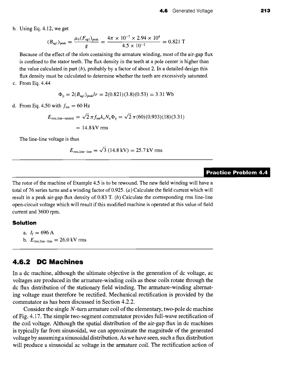
b. Using Eq. 4.12, we get
/£0(Fagl)peak
4zr
× 10 -7 X
2.94
× 104
(Bagl)peak = = = 0.821 T
g 4.5 × 10 -2
Because of the effect of the slots containing the armature winding, most of the air-gap flux
is confined to the stator teeth. The flux density in the teeth at a pole center is higher than
the value calculated in part (b), probably by a factor of about 2. In a detailed design this
flux density must be calculated to determine whether the teeth are excessively saturated.
c. From Eq. 4.44
dpp -- 2(Bagl)peaklr "-
2(0.821)(3.8)(0.53)
= 3.31 Wb
d. From Eq. 4.50 with
fme =
60 Hz
Erms,li ...... tral = ~
2"(fmekaNaf~p -- ~
zr(60)(0.933)(18)(3.31)
= 14.8 kV rms
The line-line voltage is thus
Erms,line-line = "v/-~ (14.8
kV) = 25.7 kV rms
)ractice Problem 4.,
The rotor of the machine of Example 4.5 is to be rewound. The new field winding will have a
total of 76 series turns and a winding factor of 0.925. (a) Calculate the field current which will
result in a peak air-gap flux density of 0.83 T. (b) Calculate the corresponding rms line-line
open-circuit voltage which will result if this modified machine is operated at this value of field
current and 3600 rpm.
Solution
a. If = 696 A
b. E
.... line-line =
26.0 kV rms
4.6.2 DC Machines
In a dc machine, although the ultimate objective is the generation of dc voltage, ac
voltages are produced in the armature-winding coils as these coils rotate through the
dc flux distribution of the stationary field winding. The armature-winding alternat-
ing voltage must therefore be rectified. Mechanical rectification is provided by the
commutator as has been discussed in Section 4.2.2.
Consider the single N-turn armature coil of the elementary, two-pole dc machine
of Fig. 4.17. The simple two-segment commutator provides full-wave rectification of
the coil voltage. Although the spatial distribution of the air-gap flux in dc machines
is typically far from sinusoidal, we can approximate the magnitude of the generated
voltage by assuming a sinusoidal distribution. As we have seen, such a flux distribution
will produce a sinusoidal ac voltage in the armature coil. The rectification action of
214 CHAPTER 4 Introduction to Rotating Machines
e
r
0 Jr 2n" cot
Figure
4.33 Voltage between the
brushes in the elementary dc machine
of Fig. 4.17.
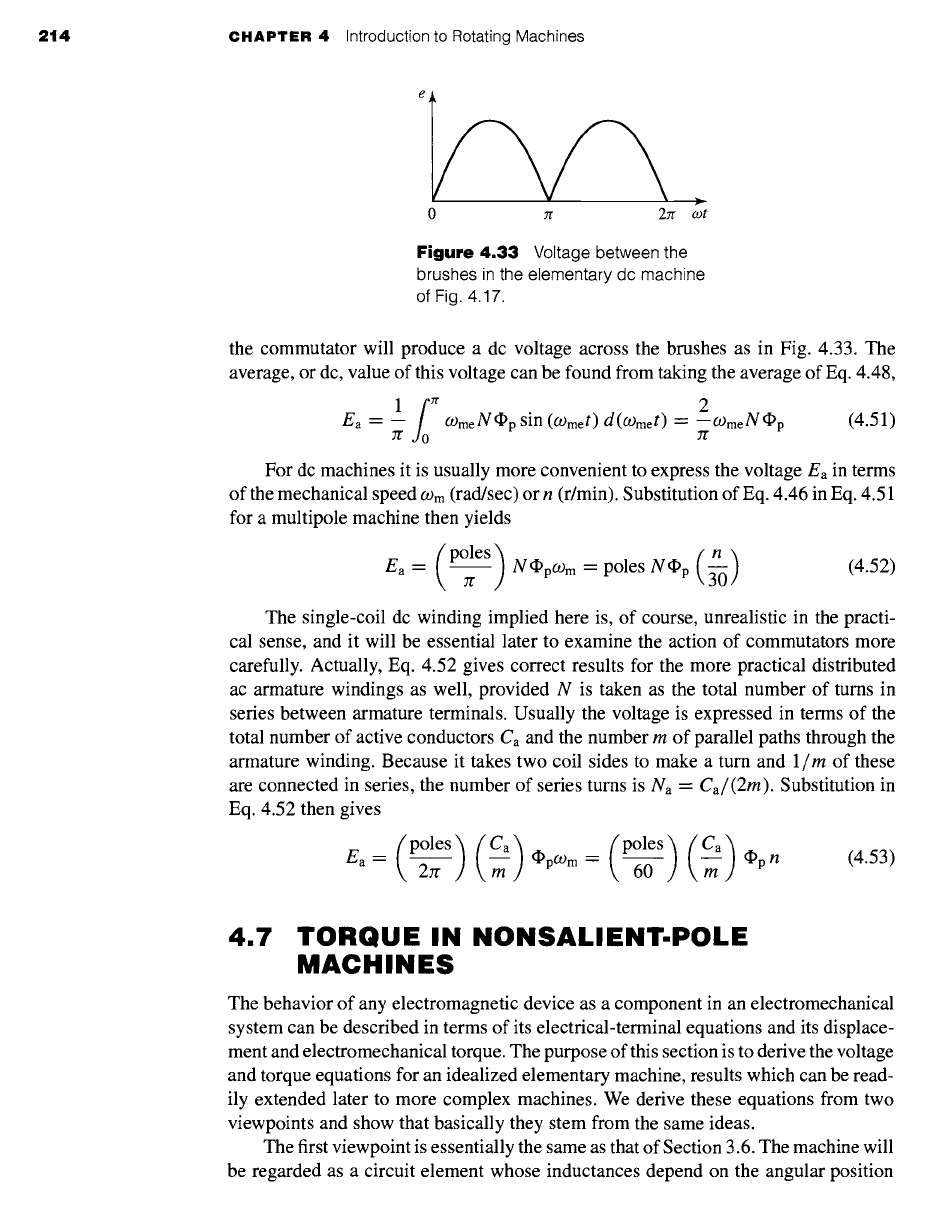
the commutator will produce a dc voltage across the brushes as in Fig. 4.33. The
average, or dc, value of this voltage can be found from taking the average of Eq. 4.48,
lf0 2
Ea -- -- OgmeN~p sin (O)met) d(o)met) --- --OgmeN~p
(4.51)
7f
For dc machines it is usually more convenient to express the voltage Ea in terms
of the mechanical speed
09 m
(rad/sec) or n (r/min). Substitution of Eq. 4.46 in Eq. 4.51
for a multipole machine then yields
( )
(n)
Ea --
polesTr N~p(_Om
=
poles N~p 3-0
(4.52)
The single-coil dc winding implied here is, of course, unrealistic in the practi-
cal sense, and it will be essential later to examine the action of commutators more
carefully. Actually, Eq. 4.52 gives correct results for the more practical distributed
ac armature windings as well, provided N is taken as the total number of turns in
series between armature terminals. Usually the voltage is expressed in terms of the
total number of active conductors Ca and the number m of parallel paths through the
armature winding. Because it takes two coil sides to make a turn and 1/m of these
are connected in series, the number of series turns is Na =
Ca/(2m).
Substitution in
Eq. 4.52 then gives
_ { poles
27r )(--~) ~pO)m= (poles
60 ) (--~)*pn (4.53)
Ea
4.7 TORQUE IN NONSALIENT-POLE
MACHINES
The behavior of any electromagnetic device as a component in an electromechanical
system can be described in terms of its electrical-terminal equations and its displace-
ment and electromechanical torque. The purpose of this section is to derive the voltage
and torque equations for an idealized elementary machine, results which can be read-
ily extended later to more complex machines. We derive these equations from two
viewpoints and show that basically they stem from the same ideas.
The first viewpoint is essentially the same as that of Section 3.6. The machine will
be regarded as a circuit element whose inductances depend on the angular position
4,7 Torque in Nonsalient-Pole Machines 215
of the rotor. The flux linkages ~. and magnetic field coenergy will be expressed in
terms of the currents and inductances. The torque can then be found from the partial
derivative of the energy or coenergy with respect to the rotor position and the terminal
voltages from the sum of the resistance drops
Ri
and the Faraday-law voltages
d~./dt.
The result will be a set of nonlinear differential equations describing the dynamic
performance of the machine.
The second viewpoint regards the machine as two groups of windings producing
magnetic flux in the air gap, one group on the stator, and the other on the rotor. By
making suitable assumptions regarding these fields (similar to those used to derive an-
alytic expressions for the inductances), simple expressions can be derived for the flux
linkages and the coenergy in the air gap in terms of the field quantities. The torque and
generated voltage can then be found from these expressions. In this fashion, torque can
be expressed explicitly as the tendency for two magnetic fields to align, in the same
way that permanent magnets tend to align, and generated voltage can be expressed in
terms of the relative motion between a field and a winding. These expressions lead to
a simple physical picture of the normal steady-state behavior of rotating machines.
4.7.1 Coupled.Circuit Viewpoint
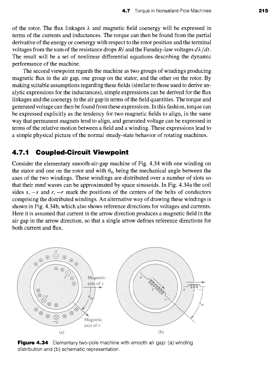
Consider the elementary smooth-air-gap machine of Fig. 4.34 with one winding on
the stator and one on the rotor and with 0m being the mechanical angle between the
axes of the two windings. These windings are distributed over a number of slots so
that their mmf waves can be approximated by space sinusoids. In Fig. 4.34a the coil
sides s,-s and r,-r mark the positions of the centers of the belts of conductors
comprising the distributed windings. An alternative way of drawing these windings is
shown in Fig. 4.34b, which also shows reference directions for voltages and currents.
Here it is assumed that current in the arrow direction produces a magnetic field in the
air gap in the arrow direction, so that a single arrow defines reference directions for
both current and flux.
(a) (b)
Figure 4.34
Elementary two-pole machine with smooth air gap: (a) winding
distribution and (b) schematic representation.