Fitzgerald A.E. Electric Machinery
Подождите немного. Документ загружается.

186 CHAPTER 4 Introduction to Rotating Machines
A, rmature
:oil, N turns
Rotation
Carbon brush
Copper
commutator
segments
Figure
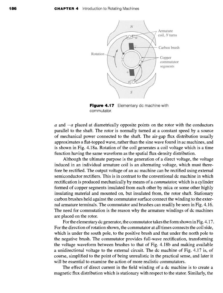
4.17 Elementary dc machine with
commutator.
a and -a placed at diametrically opposite points on the rotor with the conductors
parallel to the shaft. The rotor is normally turned at a constant speed by a source
of mechanical power connected to the shaft. The air-gap flux distribution usually
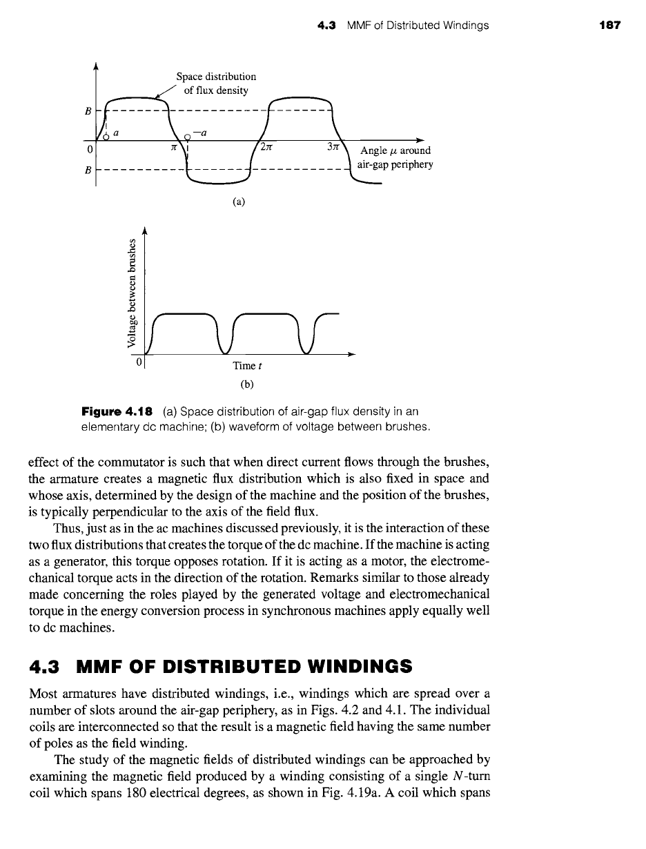
approximates a flat-topped wave, rather than the sine wave found in ac machines, and
is shown in Fig. 4.18a. Rotation of the coil generates a coil voltage which is a time
function having the same waveform as the spatial flux-density distribution.
Although the ultimate purpose is the generation of a direct voltage, the voltage
induced in an individual armature coil is an alternating voltage, which must there-
fore be rectified. The output voltage of an ac machine can be rectified using external
semiconductor rectifiers. This is in contrast to the conventional dc machine in which
rectification is produced mechanically by means of a
commutator, which is a cylinder
formed of copper segments insulated from each other by mica or some other highly
insulating material and mounted on, but insulated from, the rotor shaft. Stationary
carbon brushes held against the commutator surface connect the winding to the exter-
nal armature terminals. The commutator and brushes can readily be seen in Fig. 4.16.
The need for commutation is the reason why the armature windings of dc machines
are placed on the rotor.
For the elementary dc generator, the commutator takes the form shown in Fig. 4.17.
For the direction of rotation shown, the commutator at all times connects the coil side,
which is under the south pole, to the positive brush and that under the north pole to
the negative brush. The commutator provides full-wave rectification, transforming
the voltage waveform between brushes to that of Fig. 4.18b and making available
a unidirectional voltage to the external circuit. The dc machine of Fig. 4.17 is, of
course, simplified to the point of being unrealistic in the practical sense, and later it
will be essential to examine the action of more realistic commutators.
The effect of direct current in the field winding of a dc machine is to create a
magnetic flux distribution which is stationary with respect to the stator. Similarly, the
4,3 MMF of Distributed Windings t87
Space distribution
~~_ of flux density
~a ;i---a ...... ~[zn
an~ Angle#aroun d
. ~~__ .~ ........... ~p periphery
(a)
2
ca)
/ V V
Time t
(b)
Figure 4.18 (a) Space distribution of air-gap flux density in an
elementary dc machine; (b) waveform of voltage between brushes
effect of the commutator is such that when direct current flows through the brushes,
the armature creates a magnetic flux distribution which is also fixed in space and
whose axis, determined by the design of the machine and the position of the brushes,
is typically perpendicular to the axis of the field flux.
Thus, just as in the ac machines discussed previously, it is the interaction of these
two flux distributions that creates the torque of the dc machine. If the machine is acting
as a generator, this torque opposes rotation. If it is acting as a motor, the electrome-
chanical torque acts in the direction of the rotation. Remarks similar to those already
made concerning the roles played by the generated voltage and electromechanical
torque in the energy conversion process in synchronous machines apply equally well
to dc machines.
4.3 MMF OF DISTRIBUTED WINDINGS
Most armatures have distributed windings, i.e., windings which are spread over a
number of slots around the air-gap periphery, as in Figs. 4.2 and 4.1. The individual
coils are interconnected so that the result is a magnetic field having the same number
of poles as the field winding.
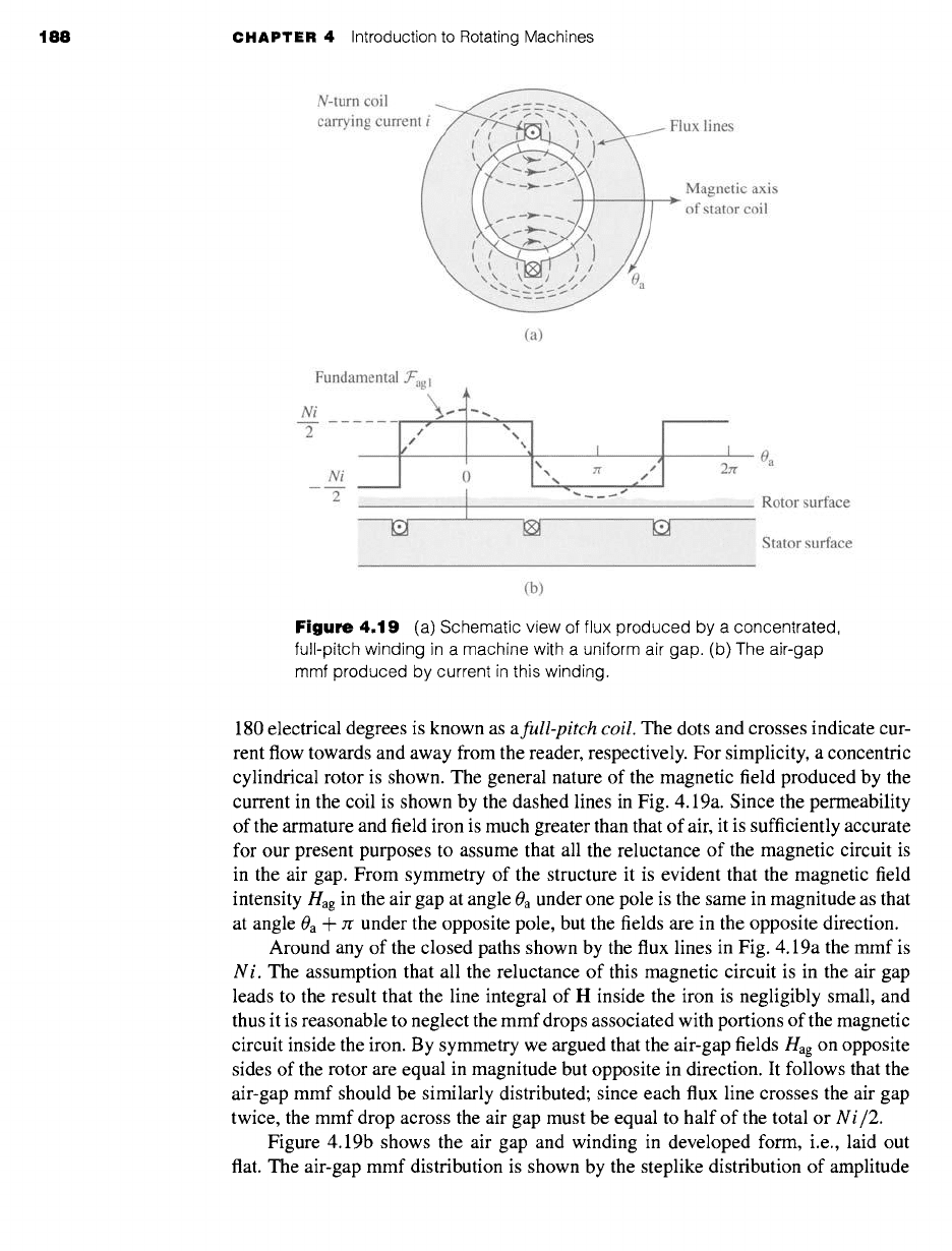
The study of the magnetic fields of distributed windings can be approached by
examining the magnetic field produced by a winding consisting of a single N-turn
coil which spans 180 electrical degrees, as shown in Fig. 4.19a. A coil which spans
188 CHAPTER 4 Introduction to Rotating Machines
N-turn coil
carrying current
ux lines
Magnetic axis
of stator coil
(a)
Fundamental
~'agl
Ni x~ .. " ~ ~ ~'~
I I Oa
%% Jr
Ni ~ / 27r
2 ] ...... Rotor surface
~ Stator surface
.... ii
(b)
Figure
4.19 (a) Schematic view of flux produced by a concentrated,
full-pitch winding in a machine with a uniform air gap. (b) The air-gap
mmf produced by current in this winding.
180 electrical degrees is known as
a full-pitch coil.
The dots and crosses indicate cur-
rent flow towards and away from the reader, respectively. For simplicity, a concentric
cylindrical rotor is shown. The general nature of the magnetic field produced by the
current in the coil is shown by the dashed lines in Fig. 4.19a. Since the permeability
of the armature and field iron is much greater than that of air, it is sufficiently accurate
for our present purposes to assume that all the reluctance of the magnetic circuit is
in the air gap. From symmetry of the structure it is evident that the magnetic field
intensity Hag in the air gap at angle 0a under one pole is the same in magnitude as that
at angle 0a + zr under the opposite pole, but the fields are in the opposite direction.
Around any of the closed paths shown by the flux lines in Fig. 4.19a the mmf is
N i.
The assumption that all the reluctance of this magnetic circuit is in the air gap
leads to the result that the line integral of H inside the iron is negligibly small, and
thus it is reasonable to neglect the mmf drops associated with portions of the magnetic
circuit inside the iron. By symmetry we argued that the air-gap fields Hag on opposite
sides of the rotor are equal in magnitude but opposite in direction. It follows that the
air-gap mmf should be similarly distributed; since each flux line crosses the air gap
twice, the mmf drop across the air gap must be equal to half of the total or
Ni/2.
Figure 4.19b shows the air gap and winding in developed form, i.e., laid out
flat. The air-gap mmf distribution is shown by the steplike distribution of amplitude
4.3 MMF of Distributed Windings 189
Ni/2. On the assumption of narrow slot openings, the mmfjumps abruptly by Ni in
crossing from one side to the other of a coil. This mmf distribution is discussed again
in Section 4.4, where the resultant magnetic fields are evaluated.
4.3.1 AC Machines
Fourier analysis can show that the air-gap mmf produced by a single coil such as the
full-pitch coil of Fig. 4.19 consists of a fundamental space-harmonic component as
well as a series of higher-order harmonic components. In the design of ac machines,
serious efforts are made to distribute the coils making up the windings so as to
minimize the higher-order harmonic components and to produce an air-gap mmf
wave which consists predominantly of the space-fundamental sinusoidal component.
It is thus appropriate here to assume that this has been done and to focus our attention
on the fundamental component.
The rectangular air-gap mmf wave of the concentrated two-pole, full-pitch coil of
Fig. 4.19b can be resolved into a Fourier series comprising a fundamental component
and a series of odd harmonics. The fundamental component
.Tagl
is
.)E'ag 1 -- -- COS Oa
T
(4.3)
where
0a
is measured from the magnetic axis of the stator coil, as shown by the dashed
sinusoid in Fig. 4.19b. It is a sinusoidal space wave of amplitude
(Fagl)peak --
__
T
(4.4)
with its peak aligned with the magnetic axis of the coil.
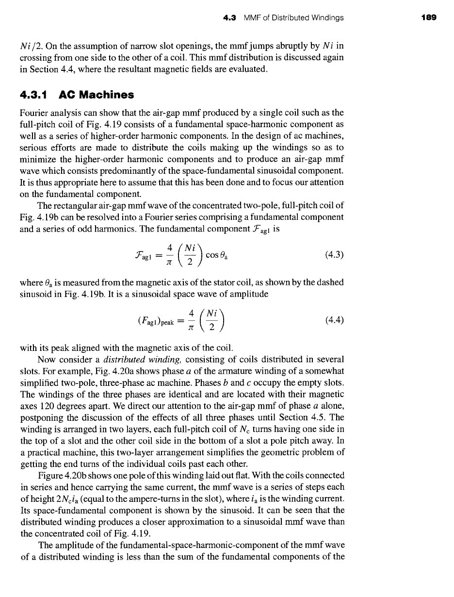
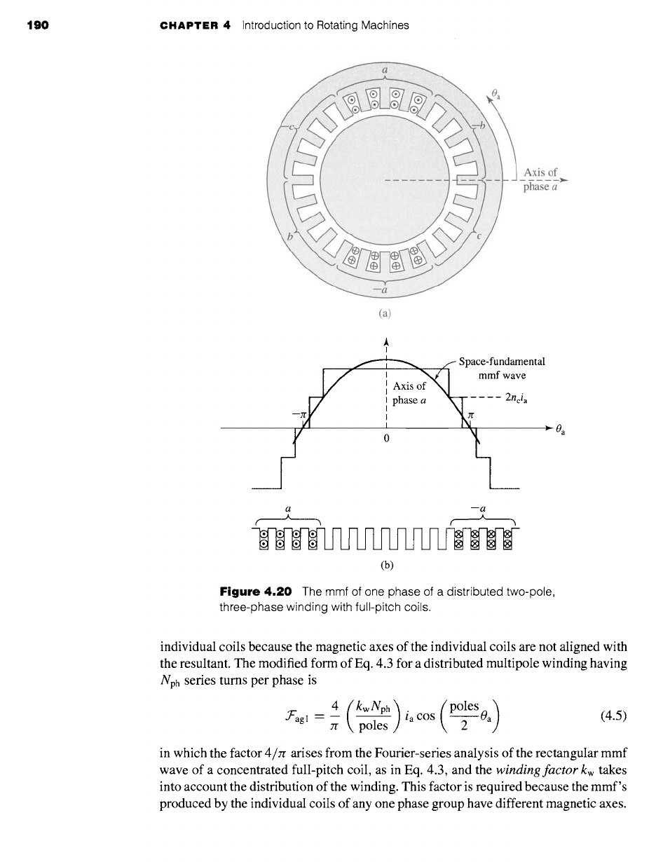
Now consider a distributed winding, consisting of coils distributed in several
slots. For example, Fig. 4.20a shows phase a of the armature winding of a somewhat
simplified two-pole, three-phase ac machine. Phases b and c occupy the empty slots.
The windings of the three phases are identical and are located with their magnetic
axes 120 degrees apart. We direct our attention to the air-gap mmf of phase a alone,
postponing the discussion of the effects of all three phases until Section 4.5. The
winding is arranged in two layers, each full-pitch coil of Nc turns having one side in
the top of a slot and the other coil side in the bottom of a slot a pole pitch away. In
a practical machine, this two-layer arrangement simplifies the geometric problem of
getting the end turns of the individual coils past each other.
Figure 4.20b shows one pole of this winding laid out fiat. With the coils connected
in series and hence carrying the same current, the mmf wave is a series of steps each
of height 2Ncia (equal to the ampere-turns in the slot), where ia is the winding current.
Its space-fundamental component is shown by the sinusoid. It can be seen that the
distributed winding produces a closer approximation to a sinusoidal mmf wave than
the concentrated coil of Fig. 4.19.
The amplitude of the fundamental-space-harmonic-component of the mmf wave
of a distributed winding is less than the sum of the fundamental components of the
190 CHAPTER 4 Introduction to Rotating Machines
Axis of
phase a
(a)
A
I
S p ac e jfu?d aavmtnta,
ff
o
ii
2ncia
>
0 a
a --a
,~, ......__...A
(b)
Figure
4.20 The mmf of one phase of a distributed two-pole,
three-phase winding with full-pitch coils.
individual coils because the magnetic axes of the individual coils are not aligned with
the resultant. The modified form of Eq. 4.3 for a distributed multipole winding having
Nph series turns per phase is
4 (po,es)
• ~"agl -- -- ia COS 0 a
(4.5)
:r poles 2
in which the factor 4/7r arises from the Fourier-series analysis of the rectangular mmf
wave of a concentrated full-pitch coil, as in Eq. 4.3, and the
winding factor kw
takes
into account the distribution of the winding. This factor is required because the mmf's
produced by the individual coils of any one phase group have different magnetic axes.
4.3 MMF of Distributed Windings 191
When they are connected in series to form the phase winding, their phasor sum is then
less than their numerical sum. (See Appendix B for details.) For most three-phase
windings, kw typically falls in the range of 0.85 to 0.95.
The factor kw Nph is the effective series turns per phase for the fundamental mmf.
The peak amplitude of this mmf wave is
(fagl)peak = -- ia (4.6)
Jr poles
"XAMPLE 4.
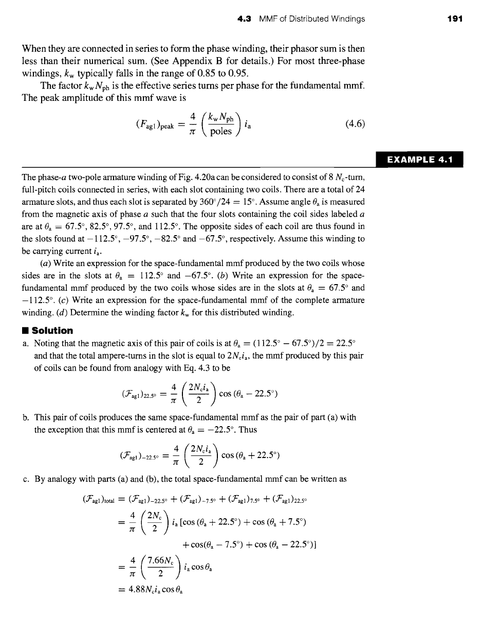
The phase-a two-pole armature winding of Fig. 4.20a can be considered to consist of 8 Nc-turn,
full-pitch coils connected in series, with each slot containing two coils. There are a total of 24
armature slots, and thus each slot is separated by 360°/24 = 15 °. Assume angle 0a is measured
from the magnetic axis of phase a such that the four slots containing the coil sides labeled a
are at 0a = 67.5 °, 82.5 °, 97.5 °, and 112.5 °. The opposite sides of each coil are thus found in
the slots found at - 112.5 °, -97.5 °, -82.5 ° and -67.5 °, respectively. Assume this winding to
be carrying current ia.
(a) Write an expression for the space-fundamental mmf produced by the two coils whose
sides are in the slots at 0a = 112.5 ° and -67.5 °. (b) Write an expression for the space-
fundamental mmf produced by the two coils whose sides are in the slots at 0a -- 67.5 ° and
-112.5 °. (c) Write an expression for the space-fundamental mmf of the complete armature
winding. (d) Determine the winding factor kw for this distributed winding.
I Solution
a. Noting that the magnetic axis of this pair of coils is at
(9 a =
(112.5 ° - 67.5°)/2 = 22.5 °
and that the total ampere-turns in the slot is equal to 2Ncia, the mmf produced by this pair
of coils can be found from analogy with Eq. 4.3 to be
4 (2Ncia)
(,~'agl)22.5 o -- -- COS
(0a -- 22.5 °)
rr 2
b. This pair of coils produces the same space-fundamental mmf as the pair of part (a) with
the exception that this mmf is centered at 0a -- --22.5 °. Thus
4 (2Ncia)
(,~L"agl)_22.5o = -- COS ((9 a -Jr-
22.5 °)
c. By analogy with parts (a) and (b), the total space-fundamental mmf can be written as
(,~L-'agl)total = (,~E'agl)-22.5o "31-()L-'agl)-7.5o -Jr-(,~E'agl)7.5o + (,~E'agl)22.5o
4 (2Nc)ia[COS(Oa+22.S°,+cos(Oa-k-7.5°)
+ COS(0a -- 7.5 °) + COS (0a -- 22.5°)]
4 (7"66Nc)iaCOSOa
Jr 2
-- 4.88Ncia
cos (9 a
192 CHAPTER 4 Introduction to Rotating Machines
d.
Recognizing that, for this winding
Nph
= 8Nc,
the total mmf of part (c) can be rewritten
as
4
()E'agl)total = -- ia COS 0a
zr 2
Comparison with Eq. 4.5 shows that for this winding, the winding factor is kw = 0.958.
Practice Problem 4.
Calculate the winding factor of the phase-a winding of Fig. 4.20 if the number of turns in the
four coils in the two outer pairs of slots is reduced to six while the number of turns in the four
coils in the inner slots remains at eight.
Solution
kw = 0.962
Equation 4.5 describes the space-fundamental component of the mmf wave pro-
duced by current in phase a of a distributed winding. If the phase-a current is sinusoidal
in time, e.g., ia = Im COS cot, the result will be an mmf wave which is stationary in
space and varies sinusoidally both with respect to 0a and in time. In Section 4.5 we
will study the effect of currents in all three phases and will see that the application of
three-phase currents will produce a rotating mmf wave.
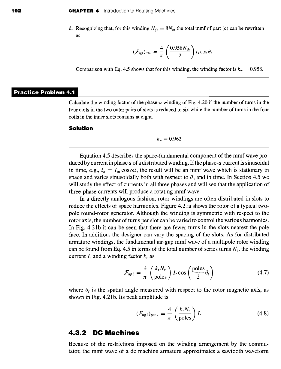
In a directly analogous fashion, rotor windings are often distributed in slots to
reduce the effects of space harmonics. Figure 4.21 a shows the rotor of a typical two-
pole round-rotor generator. Although the winding is symmetric with respect to the
rotor axis, the number of turns per slot can be varied to control the various harmonics.
In Fig. 4.21b it can be seen that there are fewer turns in the slots nearest the pole
face. In addition, the designer can vary the spacing of the slots. As for distributed
armature windings, the fundamental air-gap mmf wave of a multipole rotor winding
can be found from Eq. 4.5 in terms of the total number of series turns Nr, the winding
current Ir and a winding factor kr as
4 (krNr)(poles )
f'agl - -- Ir COS Or (4.7)
Jr poles 2
where Or is the spatial angle measured with respect to the rotor magnetic axis, as
shown in Fig. 4.21 b. Its peak amplitude is
4
(Fagl)peak -- -- Ir
Jr poles
(4.8)
4.3.2 DC Machines
Because of the restrictions imposed on the winding arrangement by the commu-
tator, the mmf wave of a dc machine armature approximates a sawtooth waveform
4.3 MMF of Distributed Windings 193
Pole faces
(a)
N10/r ~~
9'r
U8/r
/
6'r
6 7 8 9 10
mmf
Space ]
fundamental
mmf wave
N3I r
Rotor
axis
Na/r
1 2 3 4 5
(b)
Figure
4.21 The air-gap mmf of a distributed winding on the rotor of a round-rotor
generator.
more nearly than the sine wave of ac machines. For example, Fig. 4.22 shows
diagrammatically in cross section the armature of a two-pole dc machine. (In practice,
in all but the smallest of dc machines, a larger number of coils and slots would prob-
ably be used.) The current directions are shown by dots and crosses. The armature
winding coil connections are such that the armature winding produces a magnetic
194 CHAPTER 4 Introduction to Rotating Machines
Magnetic axis
of armature
windin~
Magnetic axis
of field winding
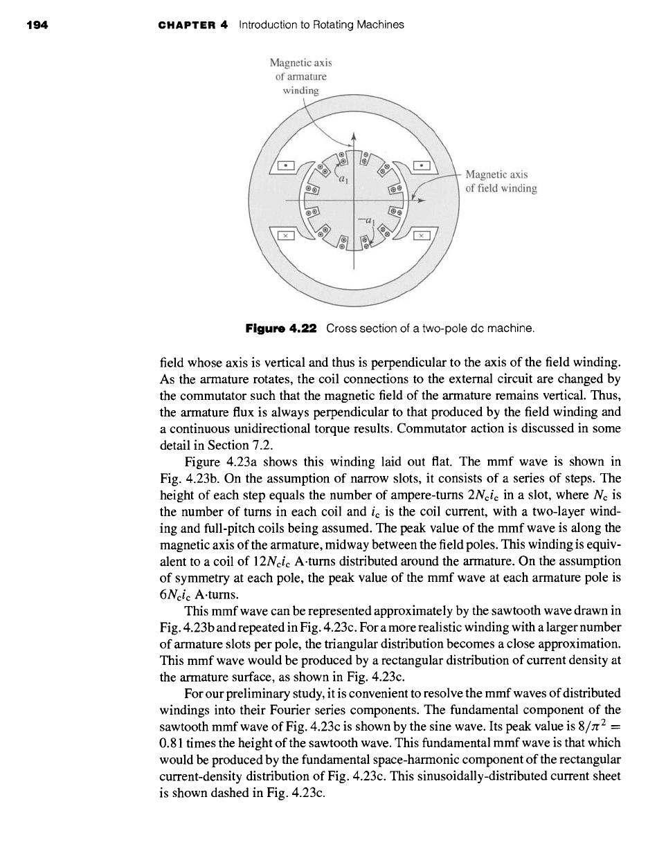
Figure 4.22
Cross section of a two-pole dc machine.
field whose axis is vertical and thus is perpendicular to the axis of the field winding.
As the armature rotates, the coil connections to the external circuit are changed by
the commutator such that the magnetic field of the armature remains vertical. Thus,
the armature flux is always perpendicular to that produced by the field winding and
a continuous unidirectional torque results. Commutator action is discussed in some
detail in Section 7.2.
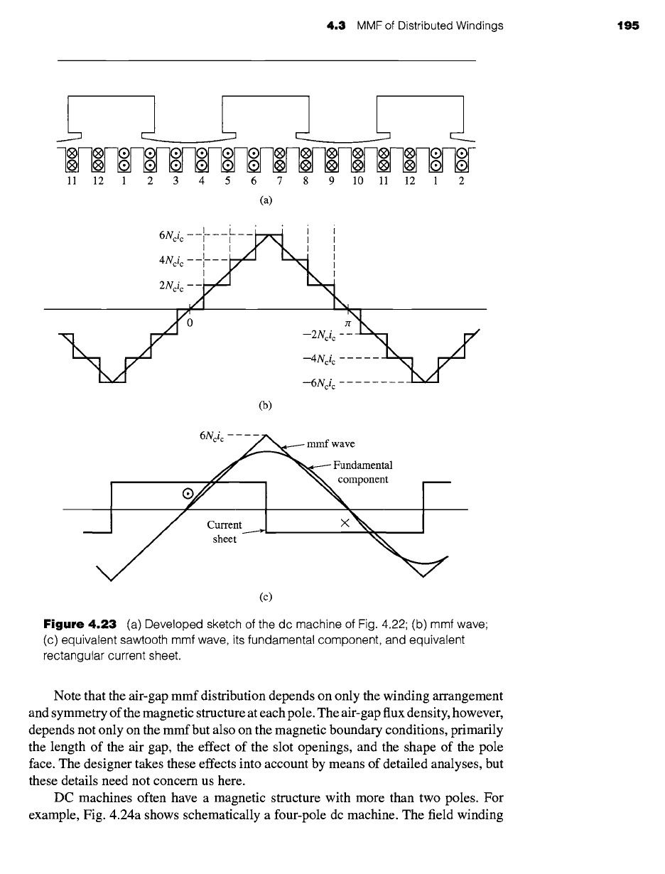
Figure 4.23a shows this winding laid out flat. The mmf wave is shown in
Fig. 4.23b. On the assumption of narrow slots, it consists of a series of steps. The
height of each step equals the number of ampere-turns 2Ncic in a slot, where Nc is
the number of turns in each coil and ic is the coil current, with a two-layer wind-
ing and full-pitch coils being assumed. The peak value of the mmf wave is along the
magnetic axis of the armature, midway between the field poles. This winding is equiv-
alent to a coil of 12Ncic A.turns distributed around the armature. On the assumption
of symmetry at each pole, the peak value of the mmf wave at each armature pole is
6Ncic A.turns.
This mmf wave can be represented approximately by the sawtooth wave drawn in
Fig. 4.23b and repeated in Fig. 4.23c. For a more realistic winding with a larger number
of armature slots per pole, the triangular distribution becomes a close approximation.
This mmf wave would be produced by a rectangular distribution of current density at
the armature surface, as shown in Fig. 4.23c.
For our preliminary study, it is convenient to resolve the mmf waves of distributed
windings into their Fourier series components. The fundamental component of the
sawtooth mmf wave of Fig. 4.23c is shown by the sine wave. Its peak value is 8/rr 2 =
0.81 times the height of the sawtooth wave. This fundamental mmf wave is that which
would be produced by the fundamental space-harmonic component of the rectangular
current-density distribution of Fig. 4.23c. This sinusoidally-distributed current sheet
is shown dashed in Fig. 4.23c.
4.3 MMF of Distributed Windings 195
1 I 1 1 I J__
~._"~ E-" "~ E"
® ® ® ® ® ® ® ® ® ® ® ® ® ® ® ®
11 12 1 2 3 4 5 6 7 8 9 10 11 12 1 2
(a)
' L__i i i i
6Ncic i I I/kl I J
I I ~!" "k I I
4Nci c I i /I
I~ ,
I
:Y "I.:
--2Nci c -~-~
--4Nci c
--6Nci c
(b)
6Ncic
mmf wave
Fundamental
component
Current____.~
X
sheet
(c)
Figure
4.23 (a) Developed sketch of the dc machine of Fig. 4.22; (b) mmf wave;
(c) equivalent sawtooth mmf wave, its fundamental component, and equivalent
rectangular current sheet.
Note that the air-gap mmf distribution depends on only the winding arrangement
and symmetry of the magnetic structure at each pole. The air-gap flux density, however,
depends not only on the mmf but also on the magnetic boundary conditions, primarily
the length of the air gap, the effect of the slot openings, and the shape of the pole
face. The designer takes these effects into account by means of detailed analyses, but
these details need not concern us here.
DC machines often have a magnetic structure with more than two poles. For
example, Fig. 4.24a shows schematically a four-pole dc machine. The field winding