Fitzgerald A.E. Electric Machinery
Подождите немного. Документ загружается.

196 CHAPTER 4 Introduction to Rotating Machines
J
V///'/~
Ca conductors
poles
(a) (b)
Figure
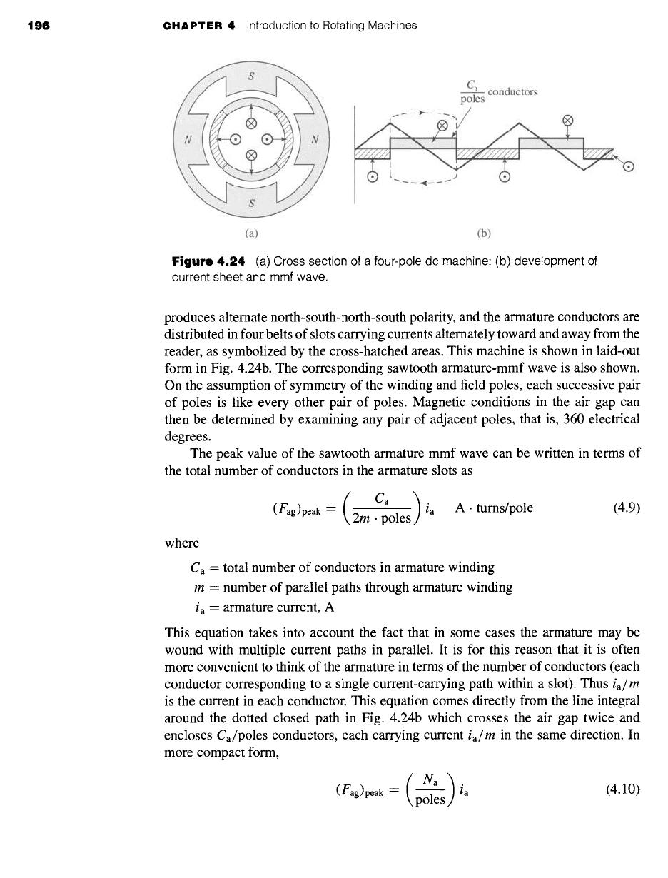
4.24 (a) Cross section of a four-pole dc machine; (b) development of
current sheet and mmf wave.
produces alternate north-south-north-south polarity, and the armature conductors are
distributed in four belts of slots carrying currents alternately toward and away from the
reader, as symbolized by the cross-hatched areas. This machine is shown in laid-out
form in Fig. 4.24b. The corresponding sawtooth armature-mmf wave is also shown.
On the assumption of symmetry of the winding and field poles, each successive pair
of poles is like every other pair of poles. Magnetic conditions in the air gap can
then be determined by examining any pair of adjacent poles, that is, 360 electrical
degrees.
The peak value of the sawtooth armature mmf wave can be written in terms of
the total number of conductors in the armature slots as
/ )
(fag)peak --
2m ~poles ia A. turns/pole (4.9)
where
Ca = total number of conductors in armature winding
m = number of parallel paths through armature winding
ia = armature current, A
This equation takes into account the fact that in some cases the armature may be
wound with multiple current paths in parallel. It is for this reason that it is often
more convenient to think of the armature in terms of the number of conductors (each
conductor corresponding to a single current-carrying path within a slot). Thus
ia/m
is the current in each conductor. This equation comes directly from the line integral
around the dotted closed path in Fig. 4.24b which crosses the air gap twice and
encloses Ca/poles conductors, each carrying current
ia/m
in the same direction. In
more compact form,
(Na)i a
(4.10)
(Fag)peak =
poles
4.4 Magnetic Fields in Rotating Machinery 197
where Na = Ca/(2m) is the number of series armature turns. From the Fourier series
for the sawtooth mmf wave of Fig. 4.24b, the peak value of the space fundamental is
given by
8
(fagl)peak -- ~
poles
(4.11)
4.4 MAGNETIC FIELDS IN ROTATING
MACHINERY
We base our preliminary investigations of both ac and dc machines on the assumption
of sinusoidal spatial distributions of mmf. This assumption will be found to give very
satisfactory results for most problems involving ac machines because their windings
are commonly distributed so as to minimize the effects of space harmonics. Because of
the restrictions placed on the winding arrangement by the commutator, the mmf waves
of dc machines inherently approach more nearly a sawtooth waveform. Nevertheless,
the theory based on a sinusoidal model brings out the essential features of dc machine
theory. The results can readily be modified whenever necessary to account for any
significant discrepancies.
It is often easiest to begin by examination of a two-pole machine, in which the
electrical and mechanical angles and velocities are equal. The results can immediately
be extrapolated to a multipole machine when it is recalled that electrical angles and
angular velocities are related to mechanical angles and angular velocities by a factor
of poles/2 (see, for example, Eq. 4.1).
The behavior of electric machinery is determined by the magnetic fields created
by currents in the various windings of the machine. This section discusses how these
magnetic fields and currents are related.
4.4.1 Machines with Uniform Air Gaps
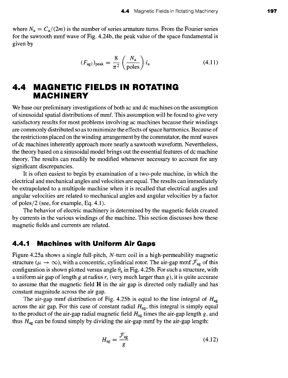
Figure 4.25a shows a single full-pitch, N-turn coil in a high-permeability magnetic
structure (/z --+ c~), with a concentric, cylindrical rotor. The air-gap mmf.Tag of this
configuration is shown plotted versus angle 0a in Fig. 4.25b. For such a structure, with
a uniform air gap of length g at radius rr (very much larger than g), it is quite accurate
to assume that the magnetic field I-I in the air gap is directed only radially and has
constant magnitude across the air gap.
The air-gap mmf distribution of Fig. 4.25b is equal to the line integral of Hag
across the air gap. For this case of constant radial Hag, this integral is simply equal
to the product of the air-gap radial magnetic field Hag times the air-gap length g, and
thus Hag can be found simply by dividing the air-gap mmf by the air-gap length:
.Fag
Hag = (4.12)
g
198 CHAPTER 4 Introduction to Rotating Machines
coil
Magnetic axis
of stator coil
(a)
..••a•/Fundamental
-~'agl
s N/ ~"
" " s
s
x 2
s
S
S ~ S
' ' I
/t
Ii
s 0 x
s
Ni ",
s
s x Jr s
2rr
I S
9 ~
.s
...............
(b)
Ni
2g ..
~, .,~j
Fundamental
Hag 1 --
H
"Ni
/ /'A"" I' ~N" ~ ag I ,/ ~ -
2 1 / s I "~ h~,,"
,,"Z l
Ni d 0 ~'~x Jr ss.q 2Jr
2g "~ -~" mmf
Fundamental ~agl
(c)
Oa
Figure 4.25
The air-gap mmf and radial component of
Hag
for a
concentrated full-pitch winding.
Thus, in Fig. 4.25c, the radial
Hag
field and mmf can be seen to be identical in form,
simply related by a factor of 1/g.
The fundamental space-harmonic component of Hag can be found directly from
the fundamental component .T'ag~, given by Eq. 4.3.
Hag 1 -- = -- cos 0a
(4.13)
g Jr
4.4 Magnetic Fields in Rotating Machinery 199
It is a sinusoidal space wave of amplitude
(nagl)peak --
__
(4.14)
For a distributed winding such as that of Fig. 4.20, the air-gap magnetic field
intensity is easily found once the air-gap mmf is known. Thus the fundamental com-
ponent of Hag can be found by dividing the fundamental component of the air-gap
mmf (Eq. 4.5) by the air-gap length g
4 ( kwNph )g.po~e (poles)
Hagl = -- ------~-s iaCOS 0a (4.15)
zr 2
This equation has been written for the general case of a multipole machine, and Nph
is the total number of series tums per phase.
Note that the space-fundamental air-gap mmf.T'agl and air-gap magnetic field Hag1
produced by a distributed winding of winding factor kw and Nph/poles series tums per
pole is equal to that produced by a concentrated, full pitch winding of (kw Npn)/poles
tums per pole. In the analysis of machines with distributed windings, this result is
useful since in considering space-fundamental quantities it permits the distributed
solution to be obtained from the single N-turn, full-pitch coil solution simply by
replacing N by the effective number of turns, kw Nph, of the distributed winding.
A four-pole synchronous ac generator with a smooth air gap has a distributed rotor winding
with 263 series turns, a winding factor of 0.935, and an air gap of length 0.7 mm. Assuming
the mmf drop in the electrical steel to be negligible, find the rotor-winding current required to
produce a peak, space-fundamental magnetic flux density of 1.6 T in the machine air gap.
II
Solution
The space-fundamental air-gap magnetic flux density can be found by multiplying the air-gap
magnetic field by the permeability of free space/.to, which in turn can be found from the space-
fundamental component of the air-gap mmf by dividing by the air-gap length g. Thus, from
Eq. 4.8
(Bagl)peak_ /A0(OL"agl)peak
4/Xo (
krNr )
-- g = :rrg ~,poles lr
and Ir can be found from
Ir = (:n'g: poles )
~k 4/z0krNr (Bagl)peak
( Zr X 0.0007 × 4 )
= 4 x 4n" x 10 .7 x 0.935 x 263 1.6
-- 11.4A
EXAMPLE 4.2
200 CHAPTER 4 Introduction to Rotating Machines
A 2-pole synchronous machine has an air-gap length of 2.2 cm and a field winding with a
total of 830 series turns. When excited by a field current of 47 A, the peak, space-fundamental
magnetic flux density in the machine air-gap is measured to be 1.35 T.
Based upon the measured flux density, calculate the field-winding winding factor kr.
Solution
kr ~- 0.952
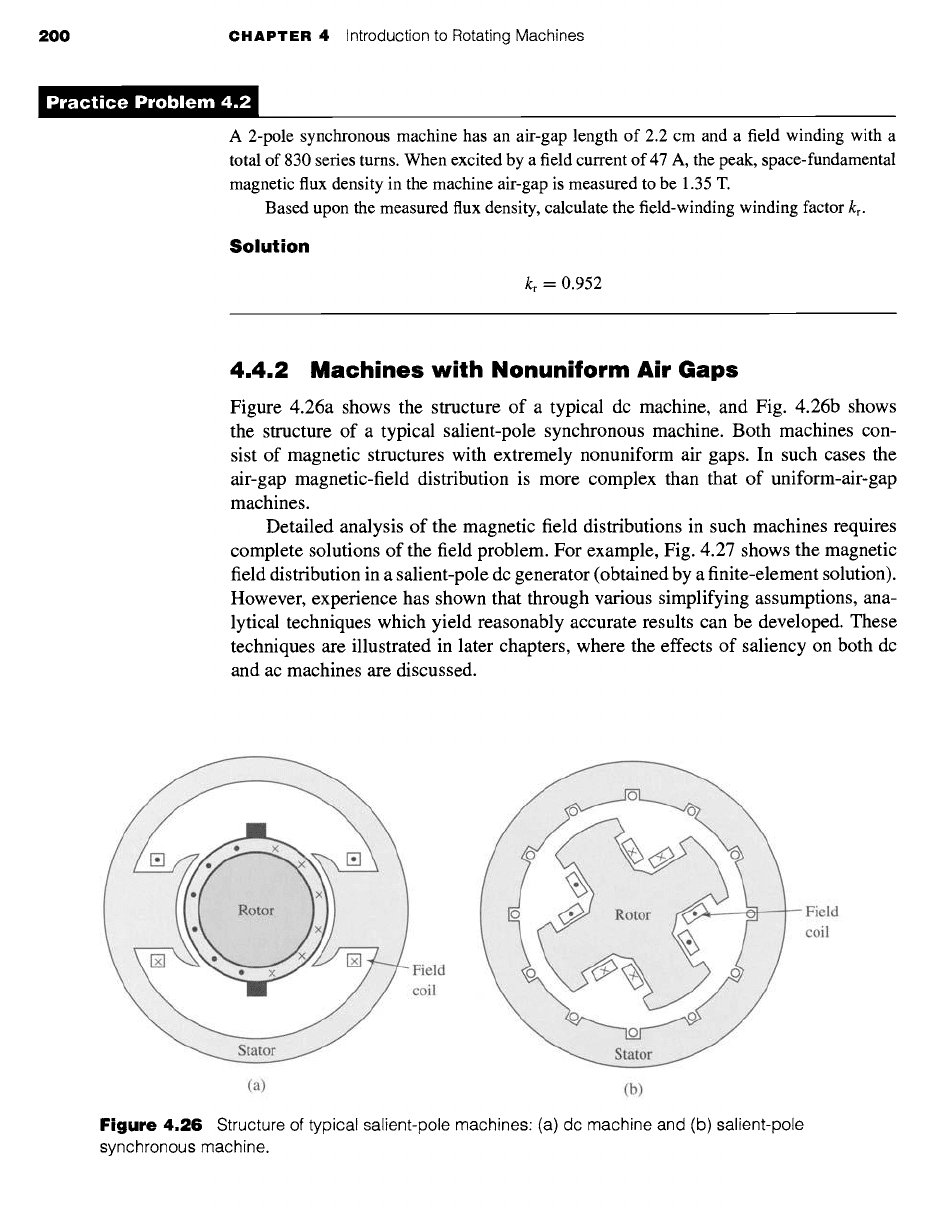
4.4.2 Machines with Nonuniform Air Gaps
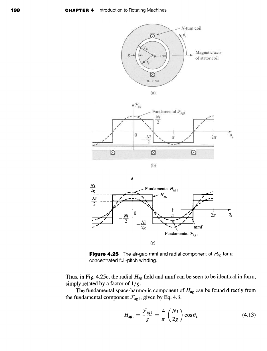
Figure 4.26a shows the structure of a typical dc machine, and Fig. 4.26b shows
the structure of a typical salient-pole synchronous machine. Both machines con-
sist of magnetic structures with extremely nonuniform air gaps. In such cases the
air-gap magnetic-field distribution is more complex than that of uniform-air-gap
machines.
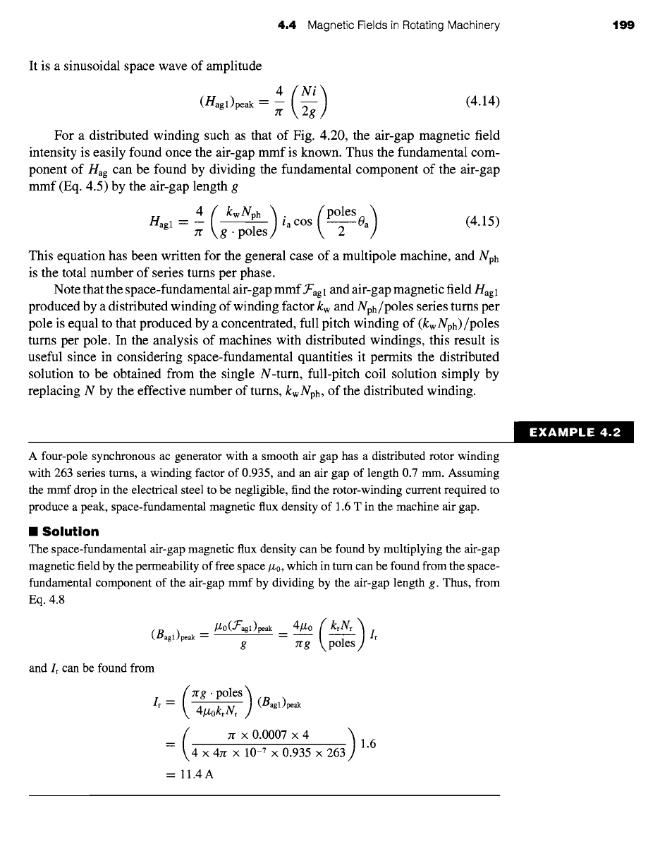
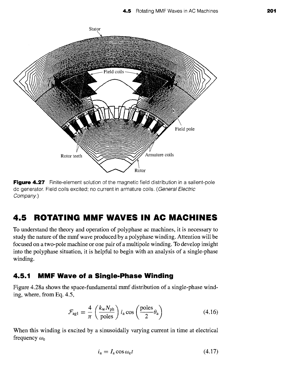
Detailed analysis of the magnetic field distributions in such machines requires
complete solutions of the field problem. For example, Fig. 4.27 shows the magnetic
field distribution in a salient-pole dc generator (obtained by a finite-element solution).
However, experience has shown that through various simplifying assumptions, ana-
lytical techniques which yield reasonably accurate results can be developed. These
techniques are illustrated in later chapters, where the effects of saliency on both dc
and ac machines are discussed.
Field
coil
Field
coil
(a) (b)
Figure
4.26 Structure of typical salient-pole machines: (a) dc machine and (b) salient-pole
synchronous machine.
4.5 Rotating MMF Waves in AC Machines 201
Stator
Field coils
Field pole
Rotor teeth
Armature coils
Rotor
Figure 4.27 Finite-element solution of the magnetic field distribution in a salient-pole
dc generator. Field coils excited no current in armature coils.
(General Electric
Company.)
4.5 ROTATING MMF WAVES IN AC MACHINES
To understand the theory and operation of polyphase ac machines, it is necessary to
study the nature of the mmf wave produced by a polyphase winding. Attention will be
focused on a two-pole machine or one pair of a multipole winding. To develop insight
into the polyphase situation, it is helpful to begin with an analysis of a single-phase
winding.
4.5.1 MMF Wave of a Single.Phase Winding
Figure 4.28a shows the space-fundamental mmf distribution of a single-phase wind-
ing, where, from Eq. 4.5,
4 (kwNph) (poles)
.T'agl = -- ia cos 0a (4.16)
Zr poles 2
When this winding is excited by a sinusoidally varying current in time at electrical
frequency
(D e
ia -- Ia COS COet (4.17)

202 CHAPTER 4 Introduction to Rotating Machines
.Tag 1 ~ Magnetic axis
/
of phase winding
Fmax
",, / "~,~.-t=0
ss S
% ~.. s
----''',_ ""
/S S~
T "',N $S ~...----
"..
x
/s S
t = t 1 ~
#S s s
I ,,~s ~ I
I ~ I
--rr ,,~_~',, ,_ t2 , ,,~ _~,, zr ~"
0ae
sssT/" 2 '~,'",..... ~, ..,-" ss 2 N~,,
-" -/ ",, -I ,'"
\-"--
--Fmad-
-- toe ~
I
(a)
Magnetic axis
of phase winding
', > Oae <
(b)
.,>
l Magnetic axis
of phase winding
y'-~ y'+
~et'~ / ]
I
I ,'~ °°et,
--U ~ ~ r--Oae
Oget'~ ~.-
• ~"ag I .....
(c)
Magnetic axis
of phase winding
Figure 4.28
Single-phase-winding space-fundamental air-gap mmf: (a) mmf
distribution of a single-phase winding at various times (b) total mmf f'agl decomposed
into two traveling waves .U- and .~'+ (c) phasor decomposition of .Uagl •
the mmf distribution is given by
(poleSoa) cOSCOet
f'agl = Fmax cos 2
= Fmax cos (0ae) cos Oget
(4.18)
Equation 4.18 has been written in a form to emphasize the fact that the result is
an mmf distribution of maximum amplitude.
4
Fmax = -- Ia (4.19)
Jr poles
4.5 Rotating MMF Waves in AC Machines 203
This mmf distribution remains fixed in space with an amplitude that varies sinusoidally
in time at frequency We, as shown in Fig. 4.28a. Note that, to simplify the notation,
Eq. 4.1 has been used to express the mmf distribution of Eq. 4.18 in terms of the
electrical angle
0ae.
Use of a common trigonometric identity 1 permits Eq. 4.18 to be rewritten in the
form
1 j
.~C'ag 1 =
fma x cos (Oae --
Wet) + -~
cos (Oae +
Wet)
(4.20)
which shows that the mmf of a single-phase winding can be resolved into two rotating
mmf waves each of amplitude one-half the maximum amplitude of -~'agl with one,
.~'a+l, traveling in the +Oa direction and the other, ~/gl, traveling in the -Oa direction,
both with electrical angular velocity
O) e
(equal to a mechanical angular velocity of
2We/poles):
1
• ~L"a~ 1 "-- ~ Fmax cos (0ae -- Oget) (4.21)
1
• ~'agl --" ~ Fmax cos (0ae + O)et) (4.22)
This decomposition is shown graphically in Fig. 4.28b and in a phasor representation
in Fig. 4.28c.
The fact that the air-gap mmf of a single-phase winding excited by a source of
alternating current can be resolved into rotating traveling waves is an important con-
ceptual step in understanding ac machinery. As shown in Section 4.5.2, in polyphase
ac machinery the windings are equally displaced in space phase, and the winding cur-
rents are similarly displaced in time phase, with the result that the negative-traveling
flux waves of the various windings sum to zero while the positive-traveling flux waves
reinforce, giving a single positive-traveling flux wave.
In single-phase ac machinery, the positive-traveling flux wave produces useful
torque while the negative-traveling flux wave produces both negative and pulsating
torque as well as losses. These machines are designed so as to minimize the effects
of the negative-traveling flux wave, although, unlike in the case of polyphase machin-
ery, these effects cannot be totally eliminated.
4.5.2 MMF Wave of a Polyphase Winding
In this section we study the mmf distributions of three-phase windings such as those
found on the stator of three-phase induction and synchronous machines. The analyses
presented can be readily extended to a polyphase winding with any number of phases.
Once again attention is focused on a two-pole machine or one pair of poles of a
multipole winding.
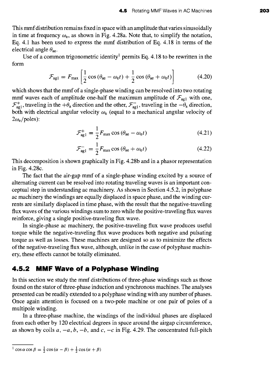
In a three-phase machine, the windings of the individual phases are displaced
from each other by 120 electrical degrees in space around the airgap circumference,
as shown by coils a, -a, b, -b, and c, -c in Fig. 4.29. The concentrated full-pitch
1 COS Or COS/~ = 1 COS (Or --/~) + 1 COS (Or "+-/~)
204
CHAPTER 4
Introduction to Rotating Machines
Axis of
phase b
Axis of
-i~
phase a
Axis of
phase c
Figure 4.29
Simplified two-pole
three-phase stator winding.
coils shown here may be considered to represent distributed windings producing si-
nusoidal mmf waves centered on the magnetic axes of the respective phases. The
space-fundamental sinusoidal mmf waves of the three phases are accordingly dis-
placed 120 electrical degrees in space. Each phase is excited by an alternating current
which varies in magnitude sinusoidally with time. Under balanced three-phase con-
ditions, the instantaneous currents are
ia = lm COS (.Oet
(4.23)
ib -- Im COS (a)et --
120 °)
(4.24)
ic = Im cos (Wet + 120 °)
(4.25)
where Im is the maximum value of the current and the time origin is arbitrarily taken
as the instant when the phase-a current is a positive maximum. The phase sequence
is assumed to be
abc.
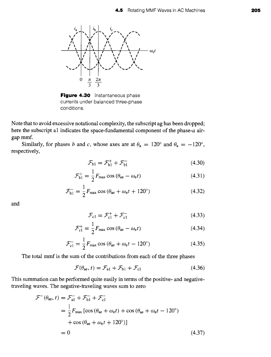
The instantaneous currents are shown in Fig. 4.30. The dots
and crosses in the coil sides (Fig. 4.29) indicate the reference directions for positive
phase currents.
The mmf of phase a has been shown to be
• ~'al -- "~'a~ -~- "~"M
(4.26)
where
1
• ~"+ = ~ Fmax cos (0ae - O)et) (4.27)
and
1
.~"~ = ~ Fma x cos (0ae -q- (-Oet) (4.28)
4
Fmax = -- Im
7r poles
(4.29)
4.5 Rotating MMF Waves in AC Machines 205
la ..
/',
% ~S II
I
I
I
I
I
I
'(
\
. S /
ic `` s - ",
,,",, ,.×
I ~ I ~ I
I I I I I
I ~ I ~ I
I I ~i
0 Jr 2zr
3 3
Figure 4.30
Instantaneous phase
currents under balanced three-phase
conditions.
O)et
Note that to avoid excessive notational complexity, the subscript ag has been dropped;
here the subscript al indicates the space-fundamental component of the phase-a air-
gap mmf.
Similarly, for phases b and c, whose axes are at 0a = 120 ° and 0a = -120 °,
respectively,
and
~-bl = ~'+ + ~'ffi (4.30)
1
~'+ -- ~ Fmax cos (0ae
--
O)et) (4.31)
1
.T'~ -- ~ Fmax cos (0ae
-~-
COet + 120 °) (4.32)
• ~"cl = -)~"~ n t- .~"~
(4.33)
1
-T "+ -- ~ fmax cos (0ae - O)et) (4.34)
1
.T'~ -- ~ Fmax cos (0ae -Jr- (-Oet --
120 °)
(4.35)
The total mmf is the sum of the contributions from each of the three phases
• ~'(0ae, t) -- .~'al -t- .~"bl -Jr- .)L"cl (4.36)
This summation can be performed quite easily in terms of the positive- and negative-
traveling waves. The negative-traveling waves sum to zero
.)c'- (0ae, t) --- .)t"~ + ~'~ nt- .~'c- i
1
= ~ Fma x [cos (0ae -~- COet) -a t- cos (0ae -Jr- COet --
120 °)
+ COS (0ae n t- O)et +
120°)]
=0
(4.37)