Fitzgerald A.E. Electric Machinery
Подождите немного. Документ загружается.

286
CHAPTER 5 Synchronous Machines
^
b o a = jIaXq
a'c = jld(Xd --
b'a t-- b"c=jIqXq
^
o'b'= jl~Xq
x~)
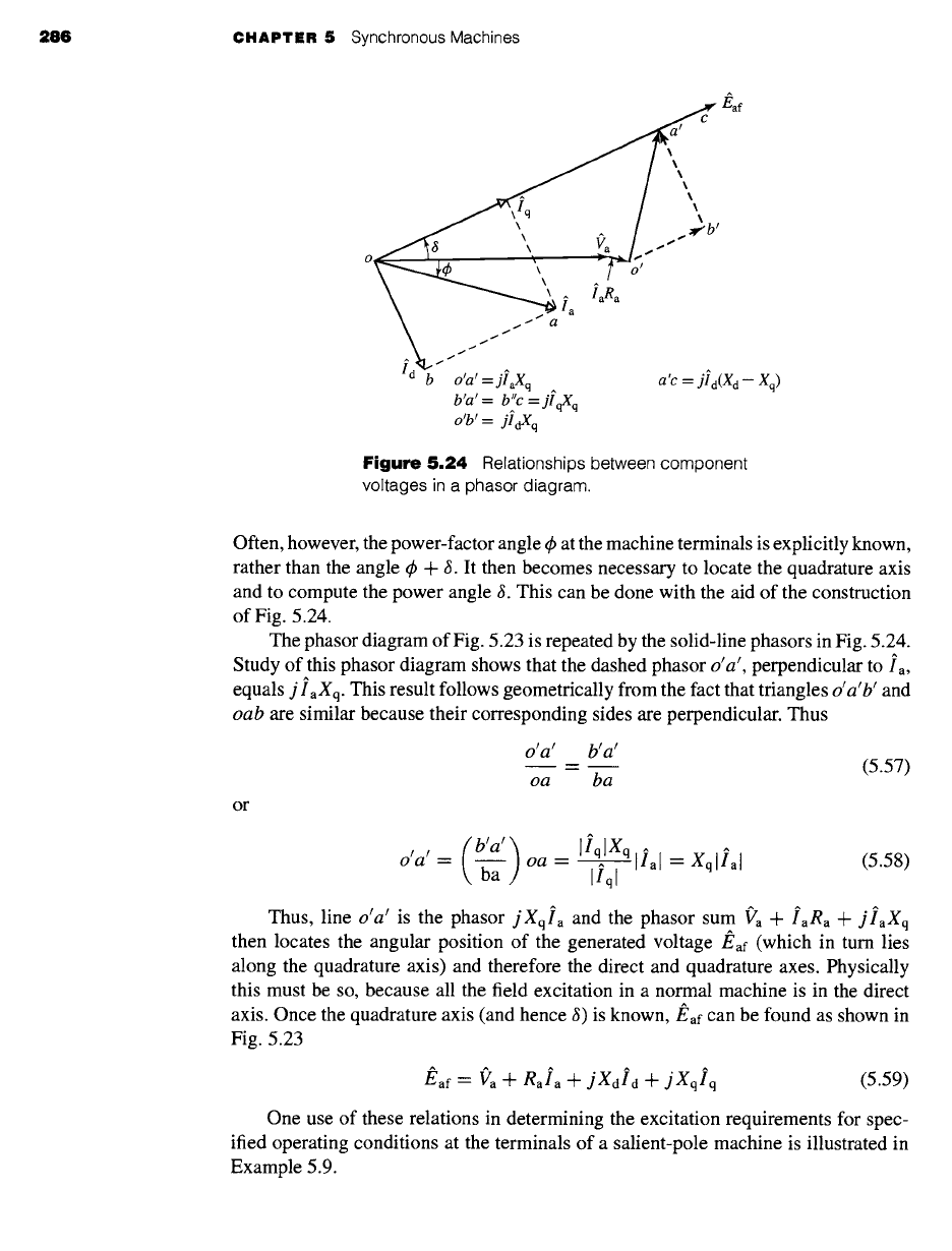
Figure
5.24 Relationships between component
voltages in a phasor diagram.
Often, however, the power-factor angle q~ at the machine terminals is explicitly known,
rather than the angle q~ + 8. It then becomes necessary to locate the quadrature axis
and to compute the power angle 8. This can be done with the aid of the construction
of Fig. 5.24.
The phasor diagram of Fig. 5.23 is repeated by the solid-line phasors in Fig. 5.24.
Study of this phasor diagram shows that the dashed phasor o'a', perpendicular to ia,
equals j iaXq. This result follows geometrically from the fact that triangles o'a'b' and
oab are
similar because their corresponding sides are perpendicular. Thus
o'a' b'a'
oa ba
or
(5.57)
(b'a'~
o'a'
= [lqlXq
-~a ,/oa
= ~- [ial = Xqlial
Ilql
(5.58)
Thus, line
o'a'
is the phasor
jXqla
and
the phasor sum f'a
+ laga a t-
jlaXq
then locates the angular position of the generated voltage
J~af
(which in turn lies
along the quadrature axis) and therefore the direct and quadrature axes. Physically
this must be so, because all the field excitation in a normal machine is in the direct
axis. Once the quadrature axis (and hence 8) is known,
J~af can
be found as shown in
Fig. 5.23
/~af "- ~'a "[- gala -'[-
j Xdid
+ j Xqlq
(5.59)
One use of these relations in determining the excitation requirements for spec-
ified operating conditions at the terminals of a salient-pole machine is illustrated in
Example 5.9.

5,6 Effects of Salient Poles Introduction to Direct- and Quadrature-Axis Theory
287
The reactances
X d
and
Xq
of a salient-pole synchronous generator are 1.00 and 0.60 per
unit, respectively. The armature resistance may be considered to be negligible. Compute the
generated voltage when the generator delivers its rated kVA at 0.80 lagging power factor and
rated terminal voltage.
II
Solution
First, the phase of/~af
must
be found so
that
~a can be resolved into its direct- and quadrature-
axis components. The phasor diagram is shown in Fig. 5.25. As is commonly done for such
problems, the terminal voltage f'a will be used as the reference phasor, i.e., ("a = Va # °°° = Va.
In per unit
la = Ia
e j~ = 0.80 - j0.60 = 1.0
e -j36"9°
The quadrature axis is located by the phasor
E' = Va -Jr- jXqla =
1.0 + j0.60(1.0 e -j36"9°) -- 1.44 e j19"4°
Thus, 6 = 19.4 °, and the phase angle
between
Eaf and
~a is (~ --¢ =
19.4 ° - (-36.9 °) = 56.3 °.
Note, that although it would appear from Fig. 5.25 that the appropriate angle is 3 + 4~, this is
not correct because the angle q~ as drawn in Fig. 5.25 is a negative angle. In general, the desired
angle is equal to the difference between the power angle and the phase angle of the terminal
current.
The armature current can now be resolved into its direct- and quadrature-axis components.
Their magnitudes are
Id = Iial sin (3 - (it)) = 1.00 sin (56.3 °) = 0.832
and
lq -- Iial COS (8 -- q~) = 1.00COS (56.3 °) = 0.555
As phasors,
i4 = 0.832
e j(-90°+19"4°) --
0.832
e j70"6°
U
A
Eaf
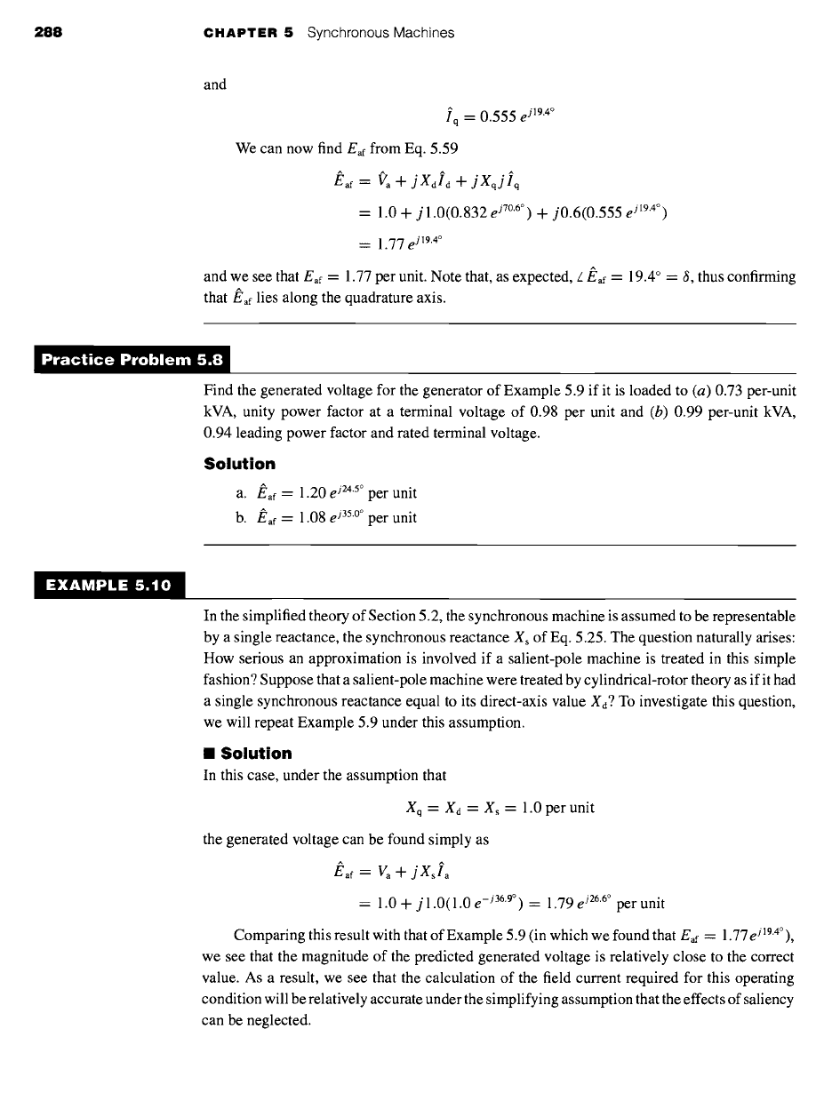
Figure
5.25 Generator phasor diagram for Example 5.9.
EXAMPLE 5.9
288 CHAPTER 5 Synchronous Machines
and
lq -- 0.555 e j19"4°
We can now find
Eaf
from Eq. 5.59
#af ~" /Vra "~-
jXdld + jXqjlq
-- 1.0 + j 1.0(0.832
e j70"6°) -+-
j0.6(0.555
e j19"4°)
= 1.77
e j19"4°
and we see that
Eaf =
1.77 per unit. Note that, as expected, L/~af = 19.4 ° = 8, thus confirming
that
#af lies along the quadrature axis.
mractice Problem 5.|
Find the generated voltage for the generator of Example 5.9 if it is loaded to (a) 0.73 per-unit
kVA, unity power factor at a terminal voltage of 0.98 per unit and (b) 0.99 per-unit kVA,
0.94 leading power factor and rated terminal voltage.
Solution
a. #af =
1.20
e j24"5°
per unit
b.
#af =
1.08 e j35"°° per unit
EXAMPLE 5.10
In the simplified theory of Section 5.2, the synchronous machine is assumed to be representable
by a single reactance, the synchronous reactance Xs of Eq. 5.25. The question naturally arises:
How serious an approximation is involved if a salient-pole machine is treated in this simple
fashion? Suppose that a salient-pole machine were treated by cylindrical-rotor theory as if it had
a single synchronous reactance equal to its direct-axis value Xd ? To investigate this question,
we will repeat Example 5.9 under this assumption.
II Solution
In this case, under the assumption that
Xq = X d = X s = 1.0 per unit
the generated voltage can be found simply as
J~af ~--
Va+jXsla
= 1.0 + j 1.0(1.0
e -j36"9°) =
1.79
e j26"6°
per unit
Comparing this result with that of Example 5.9 (in which we found that
Eaf =
1.77
eJ194°),
we see that the magnitude of the predicted generated voltage is relatively close to the correct
value. As a result, we see that the calculation of the field current required for this operating
condition will be relatively accurate under the simplifying assumption that the effects of saliency
can be neglected.
5.7 Power-Angle Characteristics of Salient-Pole Machines 289
However, the calculation of the power angle 6 (19.4 ° versus a value of 26.6 ° if saliency
is neglected) shows a considerably larger error. In general, such errors in the calculation of
generator steady-state power angles may be of significance when studying the transient behavior
of a system including a number of synchronous machines. Thus, although saliency can perhaps
be ignored when doing "back-of-the-envelope" system calculations, it is rarely ignored in
large-scale, computer-based system studies.
5.7
POWER-ANGLE CHARACTERISTICS
OF SALIENT-POLE MACHINES
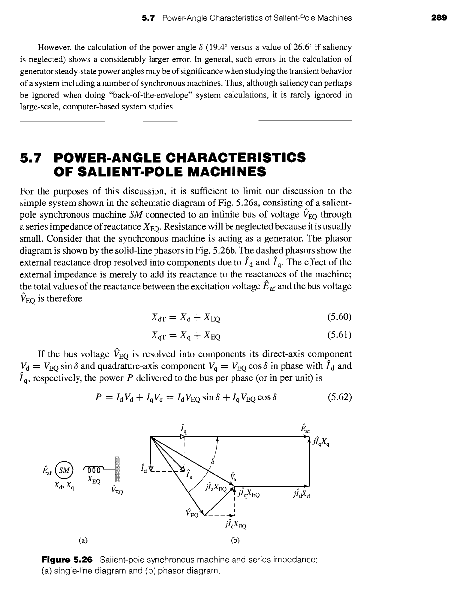
For the purposes of this discussion, it is sufficient to limit our discussion to the
simple system shown in the schematic diagram of Fig. 5.26a, consisting of a salient-
pole synchronous machine
SM
connected to an infinite bus of voltage f'EQ through
a series impedance of reactance XEQ. Resistance will be neglected because it is usually
small. Consider that the synchronous machine is acting as a generator. The phasor
diagram is shown by the solid-line phasors in Fig. 5.26b. The dashed phasors show the
external reactance drop resolved into components due to id and iq. The effect of the
external impedance is merely to add its reactance to the reactances of the machine;
the total values of the reactance between the excitation voltage/~af and the bus voltage
VEQ is therefore
XdT = Xd ~- XEQ
(5.60)
XqT = Xq + XEQ (5.61)
If the bus voltage
VEQ is
resolved into components its direct-axis component
Vd -- VEQ
sin 6 and quadrature-axis component Vq
=
VEQ cos ~ in phase with id and
iq, respectively, the power P delivered to the bus per phase (or in per unit) is
P
= IdVd -Jr- IqVq
-- IdVEQ sin~ -Jr- IqVEQ cos S
(5.62)
Xd'Xq VE Q
jidXEQ
(a) (b)
f
jlqXq
jI~d
Figure 5.26 Salient-pole synchronous machine and series impedance:
(a) single-line diagram and (b) phasor diagram.
290 CHAPTER
5 Synchronous Machines
Also, from Fig. 5.26b,
and
Eaf
-- VEQ cos 6
XdT
(5.63)
--180
q
VEQ
sin 6
XqT
(5.64)
Substitution of Eqs. 5.63 and 5.64 in Eq. 5.62 gives
P
=
EafVEQ
sin 6
+ V2Q(XdT --
XqT)
XdT 2XdTXqT
sin 26 (5.65)
Equation 5.65 is directly analogous to Eq. 5.47 which applies to the case of a
nonsalient machine. It gives the power per phase when
Eaf
and
VEQ are
expressed
as line-neutral voltages and the reactances are in ff2/phase, in which case the re-
sult must be multiplied by three to get three-phase power. Alternatively, express-
ing
Eaf
and
VEQ as
line-to-line voltages will result in three-phase power directly.
Similarly, Eq. 5.65 can be applied directly if the various quantites are expressed in
per unit.
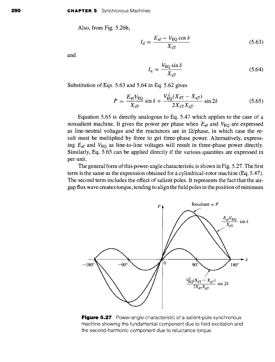
The general form of this power-angle characteristic is shown in Fig. 5.27. The first
term is the same as the expression obtained for a cylindrical-rotor machine (Eq. 5.47).
The second term includes the effect of salient poles. It represents the fact that the air-
gap flux wave creates torque, tending to align the field poles in the position of minimum
Resultant
=
P
EafVEQ sin 6
0 90o~'180 o
VE2Q(XdT--
XqT) sin 26
2xd~Xq~
Figure 5.27
Power-angle characteristic of a salient-pole synchronous
machine showing the fundamental component due to field excitation and
the second-harmonic component due to reluctance torque.
5,7
Power-Angle Characteristics of Salient-Pole Machines 291
reluctance. This term is the power corresponding to the
reluctance torque
and is of
the same general nature as the reluctance torque discussed in Section 3.5. Note that
the reluctance torque is independent of field excitation. Also note that, if XdT = XqT
as in a uniform-air-gap machine, there is no preferential direction of magnetization,
the reluctance torque is zero and Eq. 5.65 reduces to the power-angle equation for a
cylindrical-rotor machine (Eq. 5.47).
Notice that the characteristic for negative values of 3 is the same except for a
reversal in the sign of P. That is, the generator and motor regions are alike if the
effects of resistance are negligible. For generator action J~af leads fEe; for motor
action/~af lags fEe. Steady-state operation is stable over the range where the slope
of the power-angle characteristic is positive. Because of the reluctance torque, a
salient-pole machine is "stiffer" than one with a cylindrical rotor; i.e., for equal
voltages and equal values of XdT, a salient-pole machine develops a given torque at
a smaller value of 3, and the maximum torque which can be developed is somewhat
greater.
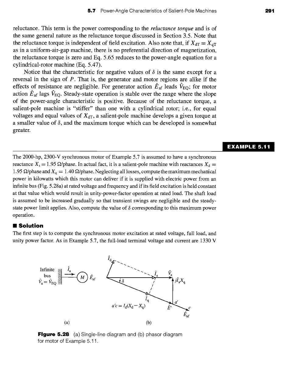
The 2000-hp, 2300-V synchronous motor of Example 5.7 is assumed to have a synchronous
reactance Xs = 1.95 f2/phase. In actual fact, it is a salient-pole machine with reactances Xd --
1.95 f2/phase and Xq = 1.40 f2/phase. Neglecting all losses, compute the maximum mechanical
power in kilowatts which this motor can deliver if it is supplied with electric power from an
infinite bus (Fig. 5.28a) at rated voltage and frequency and if its field excitation is held constant
at that value which would result in unity-power-factor operation at rated load. The shaft load
is assumed to be increased gradually so that transient swings are negligible and the steady-
state power limit applies. Also, compute the value of ~ corresponding to this maximum power
operation.
II
Solution
The first step is to compute the synchronous motor excitation at rated voltage, full load, and
unity power factor. As in Example 5.7, the full-load terminal voltage and current are 1330 V
Infinite
bus
Va-- VEQ
a'c
=/d(Xd-- Xq) Iq ~c
&f
(at (b)
Figure 5.28 (a)
Single-line diagram and (b) phasor diagram
for motor of Example 5.11.
EXAMPLE 5.11

292 CHAPTER 5 Synchronous Machines
line-to-neutral and 374 A/phase, respectively. The phasor diagram for the specified full-load
conditions is shown in Fig. 5.28b. The only essential difference between this phasor diagram
and the generator phasor diagram of Fig. 5.25 is that
Ia in
Fig. 5.28 represents motor input
current; i.e., we have switched to the motor reference direction for ~?a. Thus, switching the sign
of the current to account for the choice of the motor reference direction and neglecting the
effects of armature resistance, Eq. 5.59 becomes
Eaf = Va -
j
irdXd --
jlqXq
As in Fig. 5.28b, the quadrature axis can now be located by the phasor
E'= (la- jlaXq
= 1330--j374(1.40)= 1429e -2~~°
That is, 6 = -21.5 °,
with J~af
lagging l~'a. The magnitude of/~d
is
Id = Ia sin [6[ = 374 sin (21.5 °) = 137 A
With reference to the phasor element labeled
a'c
in Fig. 5.28b, the magnitude
of
J~af can be
found by adding the length
a'c
= Io(Xo -- Xq) numerically to the magnitude of E'; thus
Eaf ~ g' -n t- Id(Xd -- Xq) =
1429 + 137(0.55) = 1504 V line-to-neutral
(Alternatively,
Eaf
could have been determined
as Eaf ~ Va - j IdXd -- j IqXq.)
From Eq. 5.65 the power-angle characteristic for this motor is
P
= EafVEQ
sin 181 + VE:Q Xd
-- Xq
sin (2181)
Xd 2XdXq
= 1030sinlSI + 178sin(2181) kW/phase
Note that we have used
I,Sl
in this equation. That is because Eq. 5.65 as written applies to a
generator and calculates the electrical power output from the generator. For our motor, ~ is
negative and direct use of Eq. 5.65 will give a value of power P < 0 which is of course correct
for motor operation. Since we know that this is a motor and that we are calculating electric
power into the motor terminals, we ignore the sign issue here entirely and calculate the motor
power directly as a positive number.
The maximum motor input power occurs when
d P/d,~ = 0
dP
- 1030cos~ + 356cos26
d6
Setting this equal to zero and using the trigonometric identity
cos 2c~ -- 2 cos: ct - 1
permit us to solve for the angle ~ at which the maximum power occurs"
= 73.2 °
Therefore the maximum power is
Pmax = 1080 kW/phase = 3240 kW, three-phase
5.8
Permanent-Magnet AC Motors
293
We can compare this value with
emax =
3090 kW found in part (a) of Example 5.7, where
the effects of salient poles were neglected. We see that the error caused by neglecting saliency
is slightly less than five percent in this case.
)ractice Problem 5.!
A 325-MVA, 26-kV, 60-Hz, three-phase, salient-pole synchronous generator is observed to
operating at a power output of 250-MW and a lagging power factor of 0.89 at a terminal
voltage of 26 kV. The generator synchronous reactances are Xd = 1.95 and Xq = 1.18, both in
per unit. The generator achieves rated-open-circuit voltage at a field current AFNL = 342 A.
Calculate (a) the angle ~ between the generator terminal voltage and the generated voltage,
(b) the magnitude of the generated voltage
Eaf
in per unit, and (c) the required field current in
amperes.
Solution
a. 31.8 °
b. Eaf = 2.29 per unit
c. If = 783 A
The effect, as seen in Example 5.11, of salient poles on the maximum power
capability of a synchronous machine increases as the excitation voltage is decreased,
as can be seen from Eq. 5.65. Under typical operating conditions, the effect of salient
poles usually amounts to a few percent at most. Only at small excitations does the
reluctance torque become important. Thus, except at small excitations or when very
accurate results are required, a salient-pole machine usually can be adequately treated
by simple cylindrical-rotor theory.
5.8 PERMANENT-MAGNET AC MOTORS
Permanent-magnet ac motors are polyphase synchronous motors with permanent-
magnet rotors. Thus they are similar to the synchronous machines discussed up to
this point in this chapter with the exception that the field windings are replaced by
permanent magnets.
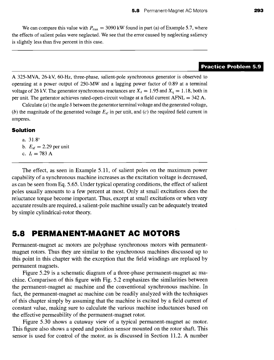
Figure 5.29 is a schematic diagram of a three-phase permanent-magnet ac ma-
chine. Comparison of this figure with Fig. 5.2 emphasizes the similarities between
the permanent-magnet ac machine and the conventional synchronous machine. In
fact, the permanent-magnet ac machine can be readily analyzed with the techniques
of this chapter simply by assuming that the machine is excited by a field current of
constant value, making sure to calculate the various machine inductances based on
the effective permeability of the permanent-magnet rotor.
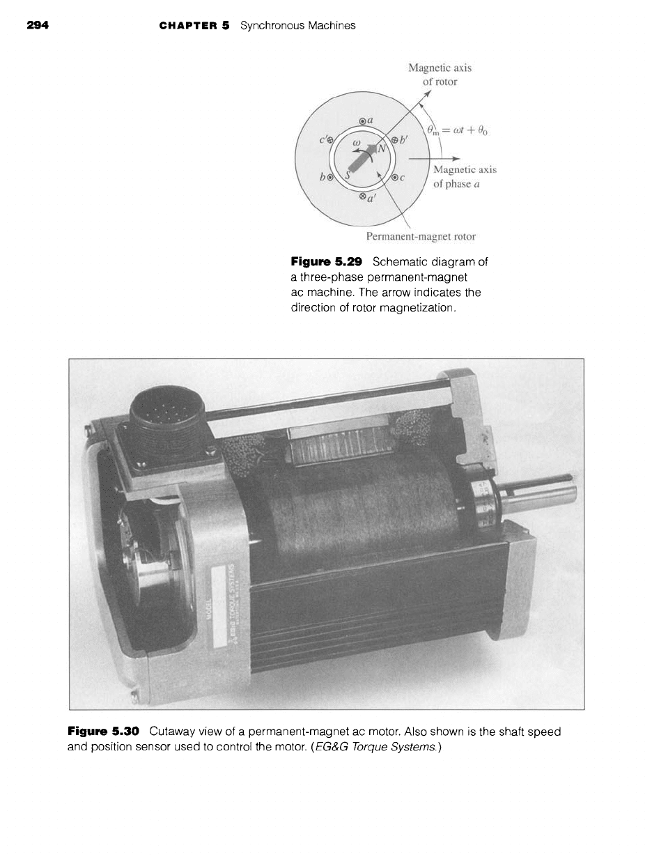
Figure 5.30 shows a cutaway view of a typical permanent-magnet ac motor.
This figure also shows a speed and position sensor mounted on the rotor shaft. This
sensor is used for control of the motor, as is discussed in Section 11.2. A number
294 CHAPTER 5 Synchronous Machines
Magnetic axis
of rotor
t+
0 o
~tic axis
se a
Permanent-magnet rotor
Figure 5.29 Schematic diagram of
a three-phase permanent-magnet
ac machine. The arrow indicates the
direction of rotor magnetization.
L i: ::i•:ii•ii:i,i::•i: i ¸
i: :i~iiiiiiii~iiii!!iiiiii~iiiiii:: ~
i l :i:: ~
:~: ~ i ~
ii!iiii:ii::~i ~ ~ ( :: : : ....... :i'~ ~:,~:~1i:1~
: ~il ~ , ' : ~ i i i::!i:.~ii :i!111 i!:i~~:~,i:i, i:ii!i
?i i ~ : ~- ':
/i:i ~ ..... . :-i,~il
r:i~:ii ¸ .... :i
:.:
i~:i~::iiiiii~!i,liiiiii~i,~ ~
Figure 5.30 Cutaway view of a permanent-magnet ac motor. Also shown is the shaft speed
and position sensor used to control the motor.
(EG&G Torque Systems.)

5.9 Summary 295
of techniques may be used for shaft-position sensing, including Hall-effect devices,
light-emitting diodes and phototransistors in combination with a pulsed wheel, and
inductance pickups.
Permanent-magnet ac motors are typically operated from variable-frequency mo-
tor drives. Under conditions of constant-frequency, sinusiodal polyphase excitation,
a permanent-magnet ac motor behaves similarly to a conventional ac synchronous
machine with constant field excitation.
An alternate viewpoint of a permanent-magnet ac motor is that it is a form of
permanent-magnet stepping motor with a nonsalient stator (see Section 8.5). Under
this viewpoint, the only difference between the two is that there will be little, if any,
saliency (cogging) torque in the permanent-magnet ac motor. In the simplest opera-
tion, the phases can be simply excited with stepped waveforms so as to cause the rotor
to step sequentially from one equilibrium position to the next. Alternatively, using
rotor-position feedback from a shaft-position sensor, the motor phase windings can be
continuously excited in such a fashion as to control the torque and speed of the motor.
As with the stepping motor, the frequency of the excitation determines the motor
speed, and the angular position between the rotor magnetic axis and a given phase
and the level of excitation in that phase determines the torque which will be produced.
Permanent-magnet ac motors are frequently referred to as
brushless motors
or
brushless dc motors.
This terminology comes about both because of the similarity,
when combined with a variable-frequency, variable-voltage drive system, of their
speed-torque characteristics to those of dc motors and because of the fact that one
can view these motors as inside-out dc motors, with their field winding on the rotor
and with their armature electronically commutated by the shaft-position sensor and
by switches connected to the armature windings.
5.9 SUMMARY
Under steady-state operating conditions, the physical picture of the operation of a
polyphase synchronous machine is simply seen in terms of the interaction of two
magnetic fields as discussed in Section 4.7.2. Polyphase currents on the stator produce
a rotating magnetic flux wave while dc currents on the rotor produce a flux wave which
is stationary with respect to the rotor. Constant torque is produced only when the rotor
rotates in synchronism with the stator flux wave. Under these conditions, there is a
constant angular displacement between the rotor and stator flux waves and the result
is a torque which is proportional to the sine of the displacement angle.
We have seen that a simple set of tests can be used to determine the signifi-
cant parameters of a synchronous machine including the synchronous reactance Xs
or Xd. Two such tests are an open-circuit test, in which the machine terminal volt-
age is measured as a function of field current, and a short-circuit test, in which the
armature is short-circuited and the short-circuit armature current is measured as a
function of field current. These test methods are a variation of a testing technique
applicable not only to synchronous machines but also to any electrical system whose
behavior can be approximated by a linear equivalent circuit to which Thevenin's