Fitzgerald A.E. Electric Machinery
Подождите немного. Документ загружается.


CHAPTER
Polyphase Induction
Machines
T
he objective of this chapter is to study the behavior of polyphase induction
machines. Our analysis will begin with the development of single-phase equiv-
alent circuits, the general form of which is suggested by the similarity of an
induction machine to a transformer. These equivalent circuits can be used to study
the electromechanical characteristics of an induction machine as well as the loading
presented by the machine on its supply source, whether it is a fixed-frequency source
such as a power system or a variable-frequency, variable-voltage motor drive.
6.1
INTRODUCTION TO POLYPHASE
INDUCTION MACHINES
As indicated in Section 4.2.1, an induction motor is one in which alternating current
is supplied to the stator directly and to the rotor by induction or transformer action
from the stator. As in the synchronous machine, the stator winding is of the type
discussed in Section 4.5. When excited from a balanced polyphase source, it will
produce a magnetic field in the air gap rotating at synchronous speed as determined
by the number of stator poles and the applied stator frequency fe (Eq. 4.41).
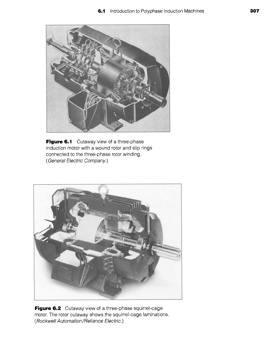
The rotor of a polyphase induction machine may be one of two types. A wound
rotor is built with a polyphase winding similar to, and wound with the same number
of poles as, the stator. The terminals of the rotor winding are connected to insulated
slip rings mounted on the shaft. Carbon brushes bearing on these rings make the rotor
terminals available external to the motor, as shown in the cutaway view in Fig. 6.1.
Wound-rotor induction machines are relatively uncommon, being found only in a
limited number of specialized applications.
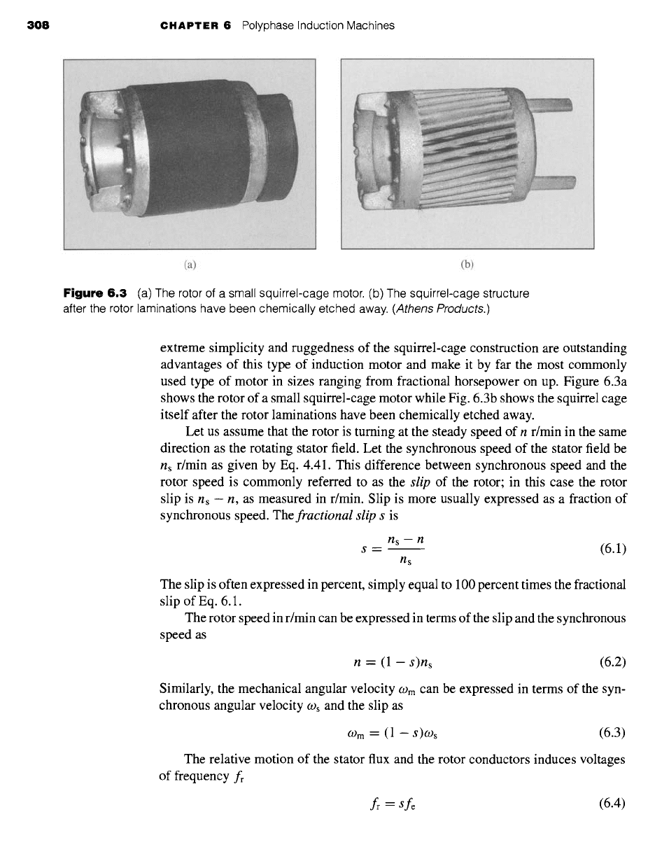
On the other hand, the polyphase induction motor shown in cutaway in Fig. 6.2
has a squirrel-cage rotor with a winding consisting of conducting bars embedded in
slots in the rotor iron and short-circuited at each end by conducting end rings. The
306
6.1 Introduction to Polyphase Induction Machines 307
Figure 6.1
Cutaway view
of a
three-phase
induction motor with a wound rotor and slip rings
connected to the three-phase rotor winding.
(General Electric Company.)
Figure 6.2
Cutaway view
of a
three-phase squirrel-cage
motor. The rotor cutaway shows the squirrel-cage laminations.
(Rockwell Automation~Reliance Electric.)
308 CHAPTER 6 Polyphase Induction Machines
(a) (b)
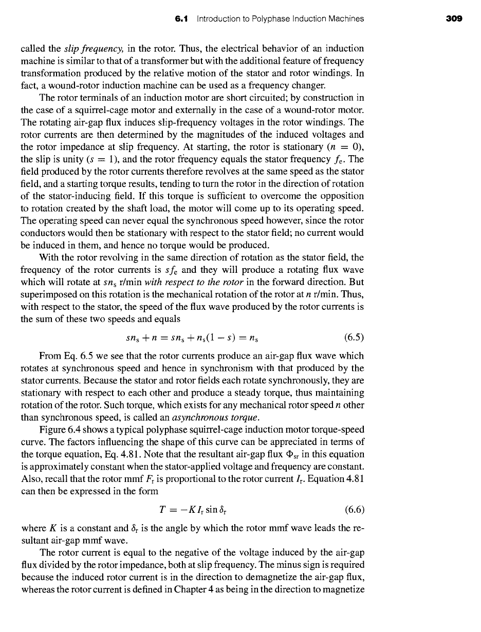
Figure
6.3 (a) The rotor of a small squirrel-cage motor. (b) The squirrel-cage structure
after the rotor laminations have been chemically etched away.
(Athens Products.)
extreme simplicity and ruggedness of the squirrel-cage construction are outstanding
advantages of this type of induction motor and make it by far the most commonly
used type of motor in sizes ranging from fractional horsepower on up. Figure 6.3a
shows the rotor of a small squirrel-cage motor while Fig. 6.3b shows the squirrel cage
itself after the rotor laminations have been chemically etched away.
Let us assume that the rotor is turning at the steady speed of n r/min in the same
direction as the rotating stator field. Let the synchronous speed of the stator field be
ns r/min as given by Eq. 4.41. This difference between synchronous speed and the
rotor speed is commonly referred to as the
slip
of the rotor; in this case the rotor
slip is ns - n, as measured in r/min. Slip is more usually expressed as a fraction of
synchronous speed. The
fractional slip s
is
ns
-n
s = (6.1)
ns
The slip is often expressed in percent, simply equal to 100 percent times the fractional
slip of Eq. 6.1.
The rotor speed in r/min can be expressed in terms of the slip and the synchronous
speed as
n --- (1 -
s)ns
(6.2)
Similarly, the mechanical angular velocity
COm
can be expressed in terms of the syn-
chronous angular velocity COs and the slip as
COm ~-- (1 -- S)COs (6.3)
The relative motion of the stator flux and the rotor conductors induces voltages
of frequency fr
fr = Sfe (6.4)
6.t Introduction to Polyphase Induction Machines 309
called the slip frequency, in the rotor. Thus, the electrical behavior of an induction
machine is similar to that of a transformer but with the additional feature of frequency
transformation produced by the relative motion of the stator and rotor windings. In
fact, a wound-rotor induction machine can be used as a frequency changer.
The rotor terminals of an induction motor are short circuited; by construction in
the case of a squirrel-cage motor and externally in the case of a wound-rotor motor.
The rotating air-gap flux induces slip-frequency voltages in the rotor windings. The
rotor currents are then determined by the magnitudes of the induced voltages and
the rotor impedance at slip frequency. At starting, the rotor is stationary (n = 0),
the slip is unity (s = 1), and the rotor fl~equency equals the stator frequency fe. The
field produced by the rotor currents therefore revolves at the same speed as the stator
field, and a starting torque results, tending to turn the rotor in the direction of rotation
of the stator-inducing field. If this torque is sufficient to overcome the opposition
to rotation created by the shaft load, the motor will come up to its operating speed.
The operating speed can never equal the synchronous speed however, since the rotor
conductors would then be stationary with respect to the stator field; no current would
be induced in them, and hence no torque would be produced.
With the rotor revolving in the same direction of rotation as the stator field, the
frequency of the rotor currents is sfe and they will produce a rotating flux wave
which will rotate at Sns r/min with respect to the rotor in the forward direction. But
superimposed on this rotation is the mechanical rotation of the rotor at n r/min. Thus,
with respect to the stator, the speed of the flux wave produced by the rotor currents is
the sum of these two speeds and equals
sns + n = Sns + ns(1 - s) = ns
(6.5)
From Eq. 6.5 we see that the rotor currents produce an air-gap flux wave which
rotates at synchronous speed and hence in synchronism with that produced by the
stator currents. Because the stator and rotor fields each rotate synchronously, they are
stationary with respect to each other and produce a steady torque, thus maintaining
rotation of the rotor. Such torque, which exists for any mechanical rotor speed n other
than synchronous speed, is called an asynchronous torque.
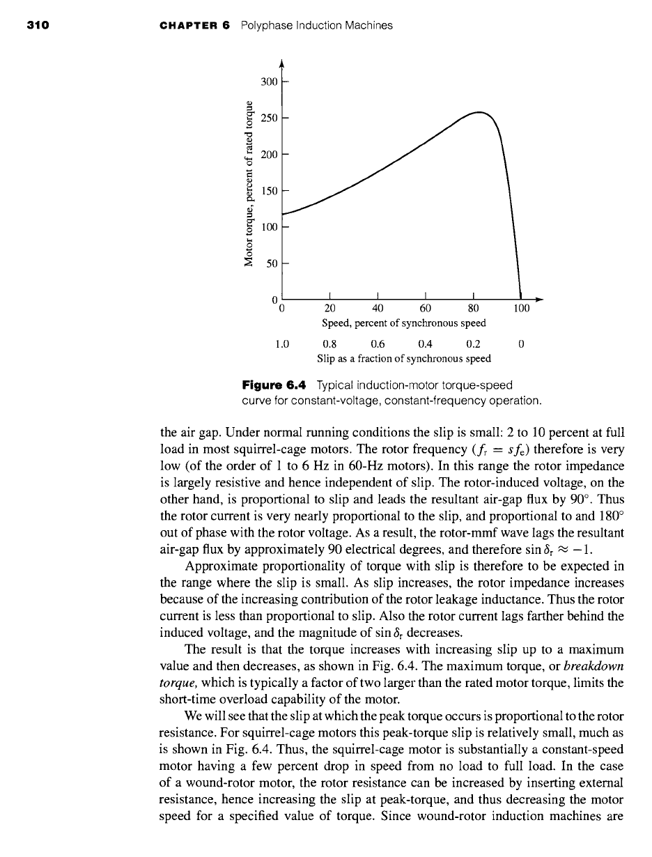
Figure 6.4 shows a typical polyphase squirrel-cage induction motor torque-speed
curve. The factors influencing the shape of this curve can be appreciated in terms of
the torque equation, Eq. 4.81. Note that the resultant air-gap flux ~sr in this equation
is approximately constant when the stator-applied voltage and frequency are constant.
Also, recall that the rotor mmf Fr is proportional to the rotor current Ir. Equation 4.81
can then be expressed in the form
T = - K Ir sin
~r
(6.6)
where K is a constant and
•r
is the angle by which the rotor mmf wave leads the re-
sultant air-gap mmf wave.
The rotor current is equal to the negative of the voltage induced by the air-gap
flux divided by the rotor impedance, both at slip frequency. The minus sign is required
because the induced rotor current is in the direction to demagnetize the air-gap flux,
whereas the rotor current is defined in Chapter 4 as being in the direction to magnetize
310 CHAPTER 6 Polyphase Induction Machines
300
=
250
o
4.a
200
o
4.a
150
~" 100
o
o
o
~ 50
0 I I I I
0 20 40 60 80
Speed, percent of synchronous speed
1.0
0.8 0.6 0.4 0.2
Slip as a fraction of synchronous speed
),,
100
Figure
6.4 Typical induction-motor torque-speed
curve for constant-voltage, constant-frequency operation.
the air gap. Under normal running conditions the slip is small: 2 to 10 percent at full
load in most squirrel-cage motors. The rotor frequency (fr =
Sfe)
therefore is very
low (of the order of 1 to 6 Hz in 60-Hz motors). In this range the rotor impedance
is largely resistive and hence independent of slip. The rotor-induced voltage, on the
other hand, is proportional to slip and leads the resultant air-gap flux by 90 ° . Thus
the rotor current is very nearly proportional to the slip, and proportional to and 180 °
out of phase with the rotor voltage. As a result, the rotor-mmf wave lags the resultant
air-gap flux by approximately 90 electrical degrees, and therefore sin gr ~ - 1.
Approximate proportionality of torque with slip is therefore to be expected in
the range where the slip is small. As slip increases, the rotor impedance increases
because of the increasing contribution of the rotor leakage inductance. Thus the rotor
current is less than proportional to slip. Also the rotor current lags farther behind the
induced voltage, and the magnitude of sin ~r decreases.
The result is that the torque increases with increasing slip up to a maximum
value and then decreases, as shown in Fig. 6.4. The maximum torque, or
breakdown
torque,
which is typically a factor of two larger than the rated motor torque, limits the
short-time overload capability of the motor.
We will see that the slip at which the peak torque occurs is proportional to the rotor
resistance. For squirrel-cage motors this peak-torque slip is relatively small, much as
is shown in Fig. 6.4. Thus, the squirrel-cage motor is substantially a constant-speed
motor having a few percent drop in speed from no load to full load. In the case
of a wound-rotor motor, the rotor resistance can be increased by inserting external
resistance, hence increasing the slip at peak-torque, and thus decreasing the motor
speed for a specified value of torque. Since wound-rotor induction machines are
6.2 Currents and Fluxes in Polyphase Induction Machines 3t I
larger, more expensive and require significantly more maintenance than squirrel-
cage machines, this method of speed control is rarely used, and induction machines
driven from constant-frequency sources tend to be limited to essentially constant-
speed applications. As we will see in Chapter 11, use of solid-state, variable-voltage,
variable-frequency drive systems makes it possible to readily control the speed of
squirrel-cage induction machines and, as a result, they are now widely used in a
wide-range of variable-speed applications.
6.2 CURRENTS AND FLUXES IN POLYPHASE
INDUCTION MACHINES
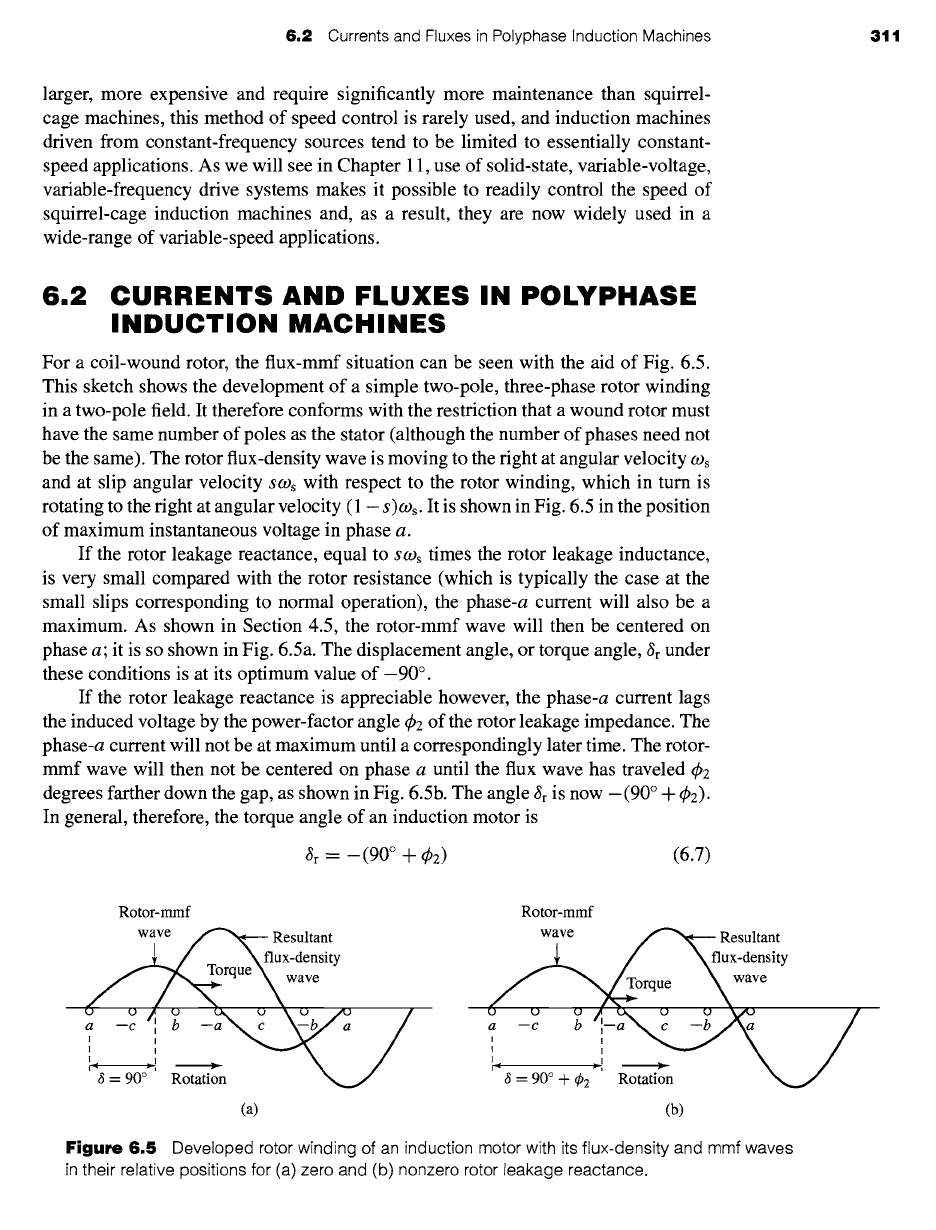
For a coil-wound rotor, the flux-mmf situation can be seen with the aid of Fig. 6.5.
This sketch shows the development of a simple two-pole, three-phase rotor winding
in a two-pole field. It therefore conforms with the restriction that a wound rotor must
have the same number of poles as the stator (although the number of phases need not
be the same). The rotor flux-density wave is moving to the fight at angular velocity COs
and at slip angular velocity SCOs with respect to the rotor winding, which in turn is
rotating to the fight at angular velocity (1 - s)COs. It is shown in Fig. 6.5 in the position
of maximum instantaneous voltage in phase a.
If the rotor leakage reactance, equal to s cos times the rotor leakage inductance,
is very small compared with the rotor resistance (which is typically the case at the
small slips corresponding to normal operation), the phase-a current will also be a
maximum. As shown in Section 4.5, the rotor-mmf wave will then be centered on
phase a; it is so shown in Fig. 6.5a. The displacement angle, or torque angle, ~r under
these conditions is at its optimum value of-90 ° .
If the rotor leakage reactance is appreciable however, the phase-a current lags
the induced voltage by the power-factor angle q~2 of the rotor leakage impedance. The
phase-a current will not be at maximum until a correspondingly later time. The rotor-
mmf wave will then not be centered on phase a until the flux wave has traveled q~2
degrees farther down the gap, as shown in Fig. 6.5b. The angle ~r is now -(90 ° + ~b2).
In general, therefore, the torque angle of an induction motor is
~r = -(90 ° + ¢2) (6.7)
Rotor-mmf
wave ,f"'x¢__ Resultant
~ \ flux-density
~
rque wave
a -c '.' -.",.. /
"3 = 90 °'' Rotation
(a)
Rotor-mmf
wave ~ Resultant
.~ / Xflux-density
/u u~°rquu e u~ ve
a --c b ~-a ~ c --b~ka /
(b)
Figure
6.5 Developed rotor winding of an induction motor with its flux-density and mmf waves
in their relative positions for (a) zero and (b) nonzero rotor leakage reactance.
312 CHAPTER 6 Polyphase Induction Machines
Flux-density wave
Instantaneous
bar-voltage ~ ~ Rotation %
magnitudes ~11"~ -- 1-- T "~ N~.
_.
Rotor'
,~]. I__L_j. j.~,~, 9 ,o ,112 ~
1415161 (l__~)(.Os
Rotation
(a)
Instantaneous
bar-current ~ o9 s
magnitudes ~ T "~" ~ X
1234 56 78 9/'q/'x~ I I I I'' \
o,.q) ~ Q q) q~ q) q~.,o ~, ® ® ® @ ® @ o
_
",.~,I / / J,-" ',/I
11 12 13 14 15 16 1 <1-Js)~ s
"-~/"~i
(b)
Rotor mmf /
wave ~'-.,~ZJ Ii I'x ~-'~_
J o \
1 2 3 4 V ~ 900 ~i~ ,-/ '~
oo~¢9Qoo¢9o~®®~®®®o
\ ___~, 6 /~i 1112 IX\141516 1 (1--~s)w
s
component of l.X.x.1 ~-q
.- d rotor-mmf wave
(c)
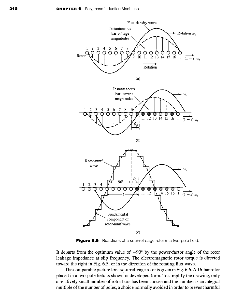
Figure 6.6
Reactions of a squirrel-cage rotor in a two-pole field.
It departs from the optimum value of -90 ° by the power-factor angle of the rotor
leakage impedance at slip frequency. The electromagnetic rotor torque is directed
toward the right in Fig. 6.5, or in the direction of the rotating flux wave.
The comparable picture for a squirrel-cage rotor is given in Fig. 6.6. A 16-bar rotor
placed in a two-pole field is shown in developed form. To simplify the drawing, only
a relatively small number of rotor bars has been chosen and the number is an integral
multiple of the number of poles, a choice normally avoided in order to prevent harmful
6.3 Induction-Motor Equivalent Circuit 313
harmonic effects. In Fig. 6.6a the sinusoidal flux-density wave induces a voltage in
each bar which has an instantaneous value indicated by the solid vertical lines.
At a somewhat later instant of time, the bar currents assume the instantaneous
values indicated by the solid vertical lines in Fig. 6.6b, the time lag corresponding
to the rotor power-factor angle q~2. In this time interval, the flux-density wave has
traveled in its direction of rotation with respect to the rotor through a space angle 4)2
and is then in the position shown in Fig. 6.6b. The corresponding rotor-mmf wave
is shown by the step wave of Fig. 6.6c. The fundamental component is shown by
the dashed sinusoid and the flux-density wave by the solid sinusoid. Study of these
figures confirms the general principle that the number of rotor poles in a squirrel-cage
rotor is determined by the inducing flux wave.
6.3
INDUCTION-MOTOR
EQUIVALENT CIRCUIT
The foregoing considerations of flux and mmf waves can readily be translated to a
steady-state equivalent circuit for a polyphase induction machine. In this derivation,
only machines with symmetric polyphase windings excited by balanced polyphase
voltages are considered. As in many other discussions of polyphase devices, it is
helpful to think of three-phase machines as being Y-connected, so that currents are
always line values and voltages always line-to-neutral values. In this case, we can
derive the equivalent circuit for one phase, with the understanding that the volt-
ages and currents in the remaining phases can be found simply by an appropriate
phase shift of those of the phase under study (-1-120 ° in the case of a three-phase
machine).
First, consider conditions in the stator. The synchronously-rotating air-gap flux
wave generates balanced polyphase counter emfs in the phases of the stator. The stator
terminal voltage differs from the counter emf by the voltage drop in the stator leakage
impedance Z1 = R1 + j X1. Thus
(Zl --/~2 + il(R1 +
jX1)
(6.8)
where
(Zl -- Stator line-to-neutral terminal voltage
/~2
--
Counter emf (line-to-neutral) generated by the resultant air-gap flux
il - Stator current
R1 -- Stator effective resistance
X1 - Stator leakage reactance
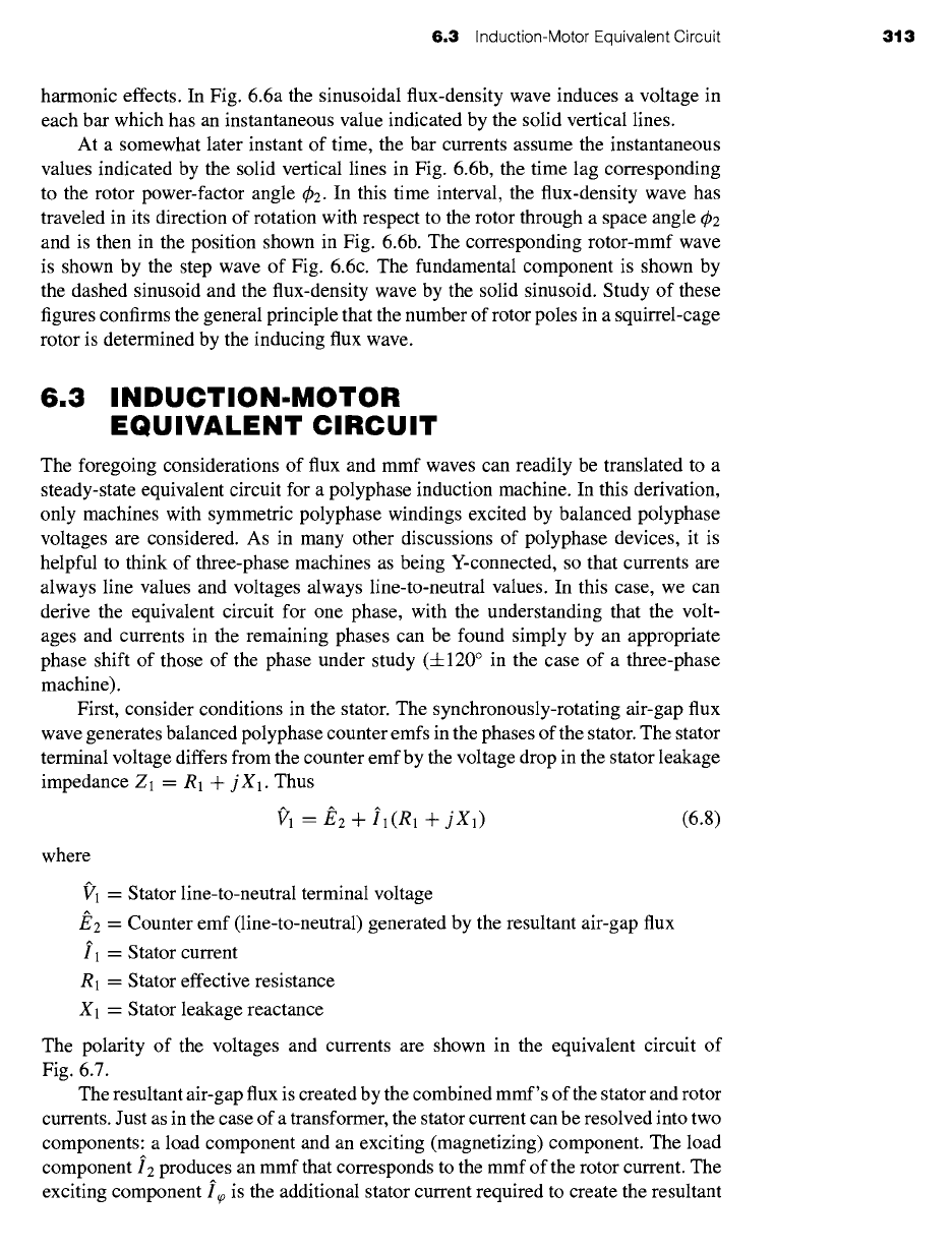
The polarity of the voltages and currents are shown in the equivalent circuit of
Fig. 6.7.
The resultant air-gap flux is created by the combined mmf's of the stator and rotor
currents. Just as in the case of a transformer, the stator current can be resolved into two
components: a load component and an exciting (magnetizing) component. The load
component
12
produces an mmf that corresponds to the mmf of the rotor current. The
exciting component i~0 is the additional stator current required to create the resultant
314 CHAPTER 6 Polyphase Induction Machines
1
R1 X1
&
Figure
6.7 Stator equivalent circuit
for a polyphase induction motor.
air-gap flux and is a function of the emf
J~2. The
exciting current can be resolved
into a core-loss component ic in phase
with
/~2 and a magnetizing component
Im
lagging/~2 by 90 °. In the equivalent circuit, the exciting current can be accounted for
by means of a shunt branch, formed by a
core-loss resistance Rc
and a
magnetizing
reactance Xm
in parallel, connected across/~2, as in Fig. 6.7. Both Rc and Xm are
usually determined at rated stator frequency and for a value of E2 close to the expected
operating value; they are then assumed to remain constant for the small departures of
E2
associated with normal operation of the motor.
The equivalent circuit representing stator phenomena is exactly like that used
to represent the primary of a transformer. To complete our model, the effects of the
rotor must be incorporated. From the point of view of the stator equivalent circuit of
Fig. 6.7, the rotor can be represented by an equivalent impedance Z2
J~2
Z 2 = ,,
(6.9)
12
corresponding to the leakage impedance of an equivalent stationary secondary. To
complete the equivalent circuit, we must determine Z2 by representing the stator and
rotor voltages and currents in terms of rotor quantities as referred to the stator.
As we saw in Section 2.3, from the point of view of the primary, the secondary
winding of a transformer can be replaced by an equivalent secondary winding having
the same number of turns as the primary winding. In a transformer where the turns ratio
and the secondary parameters are known, this can be done by referring the secondary
impedance to the primary by multiplying it by the square of the primary-to-secondary
turns ratio. The resultant equivalent circuit is perfectly general from the point of view
of primary quantities.
Similarly, in the case of a polyphase induction motor, if the rotor were to be
replaced by an equivalent rotor with a polyphase winding with the same number of
phases and turns as the stator but producing the same mmf and air gap flux as the
actual rotor, the performance as seen from the stator terminals would be unchanged.
This concept, which we will adopt here, is especially useful in modeling squirrel-cage
rotors for which the identity of the rotor "phase windings" is in no way obvious.
The rotor of an induction machine is short-circuited, and hence the impedance
seen by induced voltage is simply the rotor short-circuit impedance. Consequently
the relation between the slip-frequency leakage impedance Z2s of the equivalent rotor
6.3 Induction-Motor Equivalent Circuit 315
and the slip-frequency leakage impedance
Zroto r
of the actual rotor must be
(/~rotor )
E'2s Ne2 2
= ^ -- =
NeffZrotor
(6.10)
Zzs Izs Irotor
where Neff is the effective turns ratio between the stator winding and that of the actual
rotor winding. Here the subscript 2s refers to quantities associated with the referred
rotor. Thus/~2s is the voltage induced in the equivalent rotor by the resultant air-gap
flux,
and
I2s is the corresponding induced current.
When one is concerned with the actual rotor currents and voltages, the turns
ratio Neff must be known in order to convert back from equivalent-rotor quantities
to those of the actual rotor. However, for the purposes of studying induction-motor
performance as seen from the stator terminals, there is no need for this conversion
and a representation in terms of equivalent-rotor quantities is fully adequate. Thus
an equivalent circuit based upon equivalent-rotor quantities can be used to represent
both coil-wound and squirrel-cage rotors.
Having taken care of the effects of the stator-to-rotor turns ratio, we next must take
into account the relative motion between the stator and the rotor with the objective
of replacing the actual rotor and its slip-frequency voltages and currents with an
equivalent stationary rotor with stator-frequency voltages and currents. Consider first
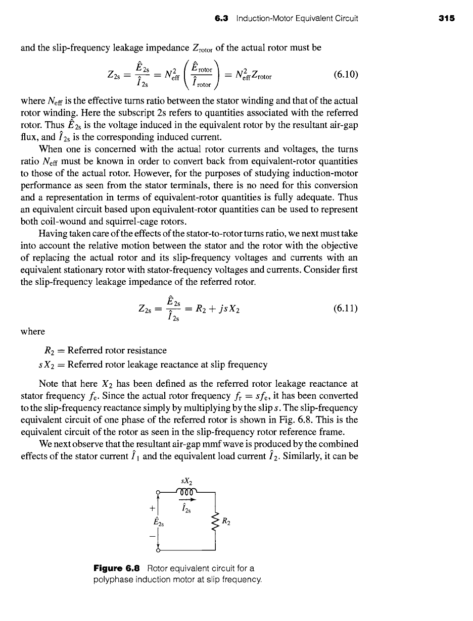
the slip-frequency leakage impedance of the referred rotor.
/~2s
Z2s
= ^ =
R2 + jsX2
(6.11)
I2s
where
R2 -- Referred rotor resistance
s X2 = Referred rotor leakage reactance at slip frequency
Note that here X2 has been defined as the referred rotor leakage reactance at
stator frequency fe. Since the actual rotor frequency fr -
Sfe,
it has been converted
to the slip-frequency reactance simply by multiplying by the slip s. The slip-frequency
equivalent circuit of one phase of the referred rotor is shown in Fig. 6.8. This is the
equivalent circuit of the rotor as seen in the slip-frequency rotor reference frame.
We next observe that the resultant air-gap mmf wave is produced by the combined
effects of the stator current il and the equivalent load current i2. Similarly, it can be
sX2
+
R2
Figure 6.8 Rotor equivalent circuit for a
polyphase induction motor at slip frequency.