Fahim M.A., Sahhaf T.A., Elkilani A.S. Fundamentals of Petroleum Refining
Подождите немного. Документ загружается.


Petroleum residues include a wide range of heavy cuts that typically
have boiling points above 345
C(650
F). These include atmospheric
residue (AR), vacuum residue (VR), heavy gas oil (HGO) and vacuum
gas oil (VGO). Heavy oils can make up to 40% residue. These residues
usually contain high metal content (Ni, V, Fe, Cu, Na), asphaltenes and
resin. Metal deposition and coke format ion cont ribute to rapid deacti-
vation of the catalysts. Typical residue and their properties are given in
Table 13.5.
A variety of hydroprocessing schemes are being used depending on feed
properties, composition, catalyst properties and target product specifica-
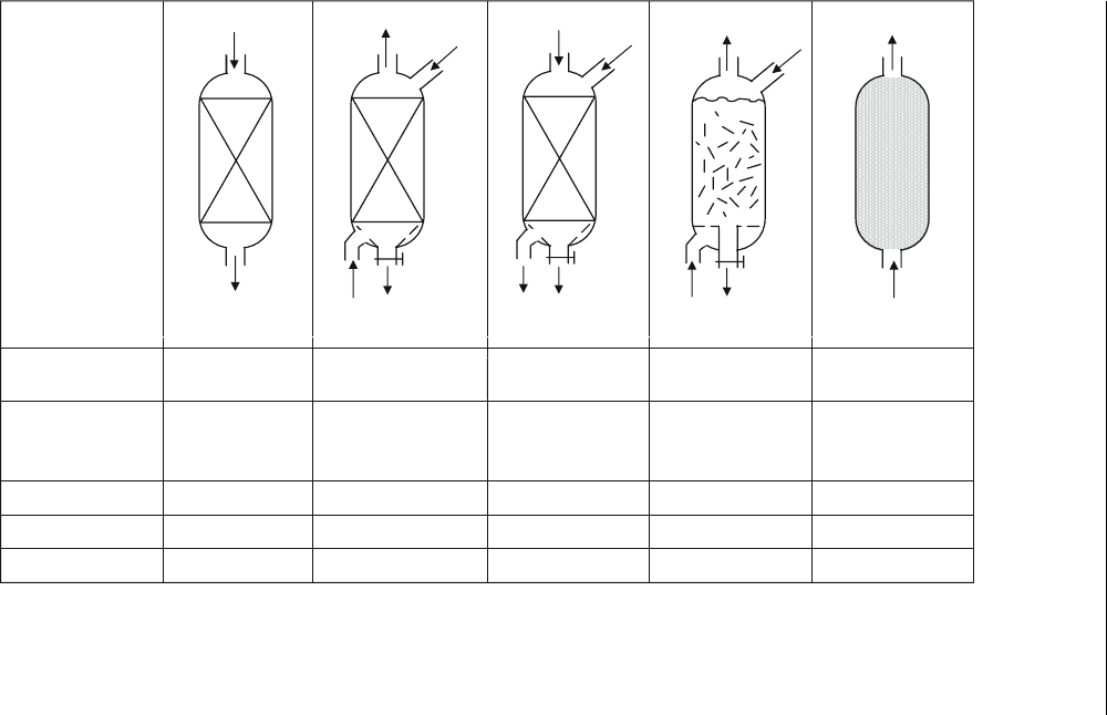
tions. These can be generally classified as: fixed bed, moving bed, ebullated
bed and slurry phase processes. A comparison of the performance of these
processes is given in Figure 13.11 (Ancheyta and Speight, 2007).
13.4.2.1. Fixed Bed Process
Fixed bed processes are the most widely used in 80% of current residue
hydroconversion processes. The process details are similar to those
described for the ARDS process in Chapter 7.
13.4.2.2. Moving Bed Process
In the moving bed processes, fresh or regenerated catalyst is added to the top
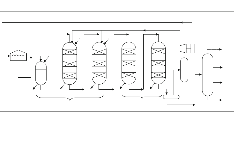
of the reactor co-currently with the feed (Hycon shell process). A flow
diagram of the Hycon process is shown in Figure 13.12. More recently,
a moving bed process was developed by adding the catalyst at the top and
Table 13.5 Properties of typical residue (Morel and Peries, 2001)
Property
Type of residue
Atmospheric
Arabian
Vacuum
Kuwait
Vacuu m
Safaniya
Yield on crude
(%wt)
48 22.5 34
SG 0.988 1.031 1.035
Viscosity at
100
C
(mm
2
/s)
95 4,010 3,900
Sulphur (wt%) 3.95 5.51 5.28
Nitrogen (wt%) 0.29 0.36 0.46
Conradson
carbon (wt%)
13.8 21.8 23
C
7
asphaltene
(wt%)
5.7 9.0 11.5
Ni þ V (ppm) 104 169 203
344 Chapter 13
Reactor
Configuration
Process
Fixed bed
(trickle bed)
Moving bed
(counter current)
RCD
VRDS (Chevron)
Hyvahl (IFP)
Licensor Hycon (Shell)
Catalyst vol% 60 60
Catalyst size, mm 1.5 x 3 1.5 x 3
Particles, cm
3
120 120
Moving bed
(cocurrent)
OCR (Chevron)
60
1.5 x 3
120
Ebullated bed
(
three phase fluidizing)
H-oil (Texaco)
KLC-Fining (Amco)
40
0.8 x 3
250
Slurry bed
CANMET
Veba Combicracking
Aurabam (UOP)
1
0.002
2.4 x10
9
HC + H
2
HC + H
2
HC + H
2
HC + H
2
HC + H
2
HC + H
2
+ Catalyst
Catalyst
HC + H
2
HC + H
2
HC + H
2
Catalyst
Catalyst
Catalyst
Catalyst
Catalyst
HC + H
2
+ Catalyst
Figure 13.11 Comparison of reactor technologies
Residue Upgrading 345
HDM Moving bed
reactors
HYCON fixed
Bed reactors
Distillation
Quench gas
Make up
gas
Vacuum
Residue
Catalyst
Catalyst
Catalyst
Catalyst
Catalyst
Catalyst
Gases
Naphtha
Kerosene
Gas oil
Figure 13.12 Hycon process flow scheme (Scheffer et al.,1997)
346 Chapter 13
the feed at the bottom (OCR Cheveron process). In both cases, the spent
catalyst is withdrawn from the bottom and regenerated outside the process.
The main advantage of the moving bed processes is that they can treat feeds
with high metal contents for a long operation.
13.4.2.3. Ebullated Bed Process
The ebullated (expanded) bed, such as H-oil is a well-established technol-
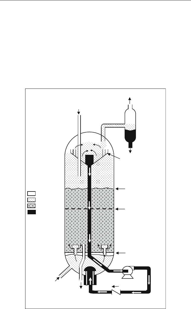
ogy. The H-oil process is based on the unique design of the reactor as
shown in Figure 13.13. This rector has several advantages over the fixed bed
reactor as follows:
Catalyst
Addition
Vapor/Liquid
Separator
Expanded
Catalyst
Level
Settled
Catalyst
Level
Recycle
Grid Plate
Gas
Liquid/Gas
Catalyst
Hydrogen and
Feed Oil
Catalyst
Withdrawal
Recycle
Oil
Li
q
ui
d
Vapors
Liquids
Figure 13.13 Ebullated bed reactor (Ra na et al., 2007)
Residue Upgrading 347

Due to the loose structure of flow inside the reactor, the solids do not
plug the flow.
Good mixing results in uniform temperatures.
Catalysts are added and withdrawn continuously, allowing for a long
period of operation.
Ebullated bed operability is more difficult than fixed bed because the
catalyst renewal operation is carried out at high pressure and temperatures.
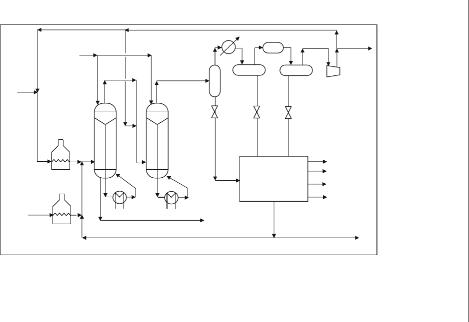
A flow scheme of H-oil with two reactors is given in Figure 13.14. The
reactor operation is compared with other options in Table 13.6. A compar-
ison of the process and operating conditions is also compared with other
processes in the same table.
13.4.2.4. Slurry Bed Process
Slurry bed processes are designed to handle residue with high dirt content,
high asphalt or even high wastes. Very fine particles of catalyst in the slurry
reactor will insure low pressure drop and a high conversion of 90%. A fixed
bed reactor is used after the slurry reactor to insure refining of the produced
light fraction. Operation of a slurry reactor is difficult. The catalyst tends to
accumulate in the reactor, leading to the plugging of down-stream
equipment.
13.4.3. Aquaconversion
The main strategy in the aquaconversion process as an option for heavy,
extra-heavy crude, with properties listed in Table 13.7, is to use a conver-
sion process severity that is just sufficient to transform heavy crudes into
gasoline and diesel.
The aquaconversion process is based on the hydrogen transfer
catalyst from water to the feedstock. The typical visbreaking technology
is limited by low conversion to control the stability of the product.
The hydrogen incorporation is high enough to saturate the free radi-
cals formed in the process. Thus, a higher conversion levels can be
achieved. Typical aquaconversion reactions (Marzin et al., 1998) are
shown in Figure 13.15. The process produces high API and low viscosity
products.
Aquaconversion technology does not produce coke and requires hydro-
gen at high pressures. Aquaconversion can be carried out in the field to
reduce handling problems.
Table 13.8 shows the level of upgrading that is obtained with aquacon-
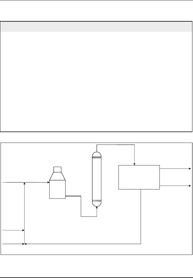
version technology. Figure 13.16 shows the scheme of the aquaconversion
process.
348 Chapter 13
Vacuum residue recycle
Fuel gas
Naphtha
Gas oil
Vacuum
Distillate
VR
Feed
furnace
H
2
furnace
Recycle
compressor
Catalyst
withdrawal
H
2
purge
Make up
Vacuum
residue
feed
Fractionation
Figure 13.14 F1ow scheme of H-oil process with two reactors (Morel and Peries, 2001)
Residue Upgrading 349

Table 13.6 Comparison of performance of residue upgrading processes (Morel and Peries, 2001)
Fixed bed Moving bed Ebullated bed Slurry bed
Maximum (Ni þ V) content in feed
(wppm)
120–400 500–700 >700 > 700
Tolerance for impurities Low Low Average High
Maximum conversion of 550
C (wt%) 60–70 60–70 80 90
Distillate quality Good Good Good Poor
Fuel oil stability Yes Yes Borderline No
Unit operability Good Difficult Difficult Difficult
Operating pressure, bar (psig) 140 (2100) 200 (3000) 100–200
(1500–3000)
135–205
(2000–3000)
Operating temperature,
C(
F) 400–450
(750–800)
400–450
(750–800)
420–450
(790–800)
450–480
(840–895)
Feed characterization Low solids High metals High metals High asphaltenes
High solids
350 Chapter 13
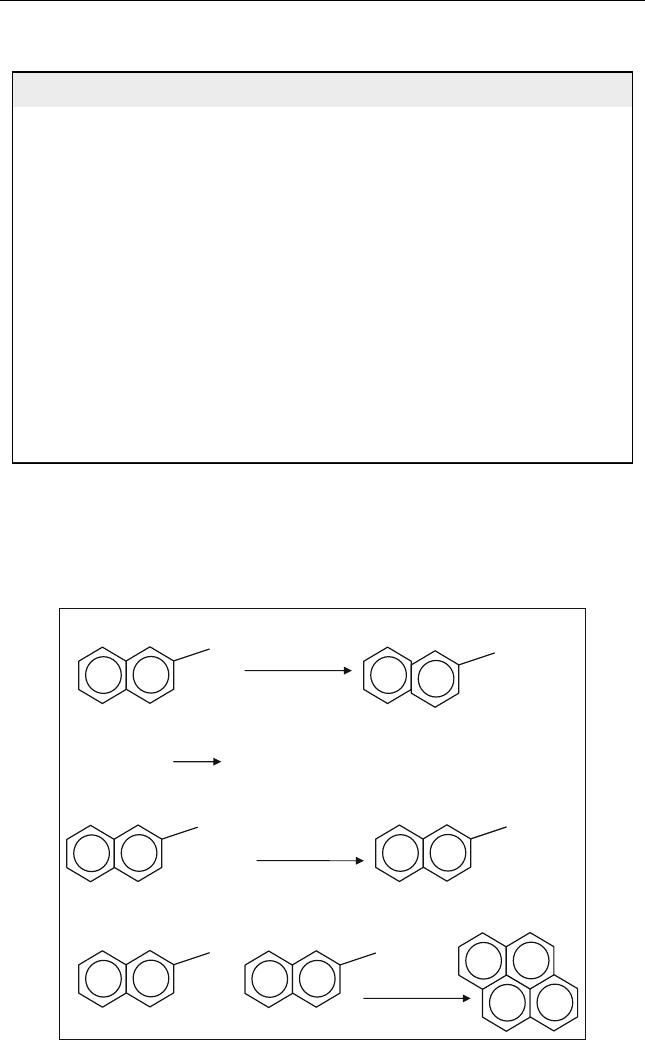
Table 13.7 Example of heavy and extra-heavy crude (Pereira et al., 2005)
Heavy cr ude Extra-heavy crude
API gravity 22.9 8.5
Sulphur (wt%) 1.13 3.96
Nitrogen (wt%) 0.22 0.73
C
7
Asphaltene (wt%) 2.0 10.2
Conradson carbon (wt%) 4.76 15.8
Vanadium (ppm) 49 488
Nickel (ppm) 11 105
Viscosity (cSt)
50
C 7.4 14,257
60
C 5.9 5533
Pour point (
C) <51 27
TAN (mg KOH/g) 0.36 2.27
Yields (vol%)
350
Cþ 52 88
520
Cþ 21 56
R-R
n
Thermal Cracking
R
+ R
n
Hydrogen Transfer
H
2
O 2H + O
Hydrogen Addition
R
+ H
RH
Condensation – Polymerization
R
+
R
Catalyst
Figure 13.15 Reactions in aquaconversion reactor
Residue Upgrading 351
Example E13.6
The following reaction occurs in the aquaconversion process:
C þ 2H
2
O ! 2H
2
þ CO
2
The bitumen feed (API ¼ 9) has the following elemental analysis:
84:3% C; 10:3% H and 5: 37% S
Table 13.8 Aquaconversion process performance ( Pereira et al., 2005)
Feedstock Extra-heavy crude Aquaconversion product
API gravity 8.5 14.0
Sulphur (wt%) 3.96 3.3
Nitrogen (wt%) 0.73 0.55
C
7
Asphaltene (wt%) 10.2 8.3
Conradson carbon (wt%) 15.8 13.6
Viscosity (cSt)
50
C 14,257 60
60
C 5533 –
100
C–8
Total acid number (TAN)
(mg KOH/g)
2.27 0.3
Yields (vol%)
350
Cþ 88
520
Cþ 56
Fractionation and
catalyst recovery
Units
Residue
Feed
Steam
Fresh
Catalyst
Heater
Reactor
Waste
catalyst
Recycle
catalyst
Product
(middle distillate)
Figure 13.16 Simplified process scheme for aquaconversion residue upgrading unit
352 Chapter 13

The maximum allowable density is 990 kg/m
3
and can be correlated with
elemental residue contents as follows:
r ¼ 1033 13:69 H wt% þ 13: 85 S wt%
How much carbon per bbl feed must react in order to meet the maximum
allowable density?
Solution:
Basis 1 bbl feed ¼ 160 kg
C ¼ 0:843ð160Þ¼134:88 kg ¼ 11 :24 kmol
Assume reaction conversion x kg C
This will produce ¼ (x/12)(2)(2) ¼ 0.33x kg hydrogen
H
2
in ¼ 0.103(160) ¼ 16.48 kg
H
2
out ¼ 16.48 þ 0.33x
wt% H
2
¼
H
2
out
mass of upgraded oil
¼
16:48 þ 0:33x
160 x 0:33x
wt% S ¼
0:0537ð160Þ
160 x 0:33x
r ¼ 990 ¼ 1033 13:68
16:48 þ 0:33x
160 x 0:33x
þ 13:85
0:0537ð160Þ
160 x 0:33x
Solving for conversion x ¼ 8.94 kg C per bbl feed
Questions and Problems
13.1. 100 kg/h residue is introduced to a deasphalting process, which
operates at 240
F. The residue has the following properties: API ¼
8, S wt% ¼ 6%. A solvent at a rate of 1200 kg/h is used. The DAO
produced has API ¼ 21. Calculate the yield of DAO and its sulphur
content.
13.2. 10,000 lb/h residue has the following properties: API ¼ 10, CCR ¼
15 wt%, S wt% ¼ 4.7 wt%, N wt% ¼ 0.7 wt%. The above feed is
introduced to a deasphalting process. Calculate the yield of DAO, its
CCR, and its sulphur and nitrogen contents.
13.3. Fuel which has the general formula C
n
H
m
S
p
is burned in a gasifier.
The dry basis flue gas analysis is as follows: O
2
0.5 vol%, SO
2
0.2 vol%,
CO 3 vol%, N
2
81.3 vol%, CO
2
15 vol%. Find the chemical formula
of the fuel burned.
13.4. The following reaction occurs in aquaconversion process:
C þ 2H
2
O ! 2H
2
þ CO
2
Residue Upgrading 353
