Fahim M.A., Sahhaf T.A., Elkilani A.S. Fundamentals of Petroleum Refining
Подождите немного. Документ загружается.


482–538
C (900–1000
F). The coke in the spent catalyst, produced in the
cracking reaction, is burned off in the regenerator by introducing excess air,
which is used to ensure the efficient combustion of coke. The produced flue
gas exits at the top of the regenerator. The hot flue gas contains carbon
dioxide, carbon monoxide water and excess air at the regenerator tempera-
ture. These gases are sent to the power recovery unit to produce super-
heated steam. The operation of the FCC remains in a steady state as long as a
heat balance exists between the heat produced in the regenerator and the
heat consumed in the reactor.
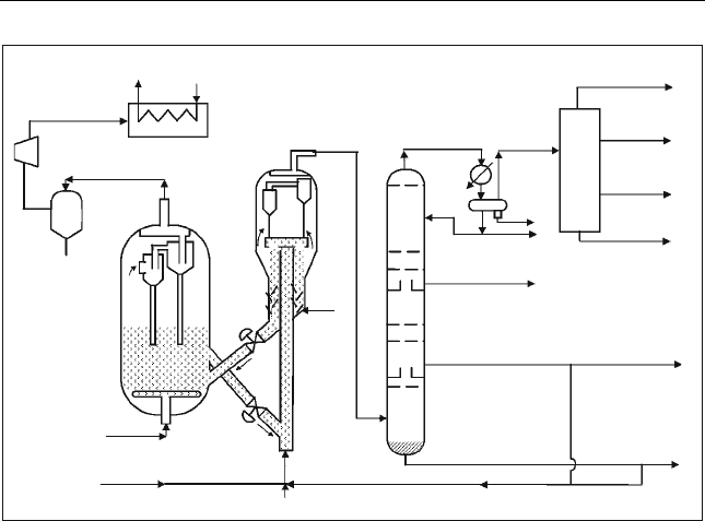
In both the reactor and the regenerator, hydrocyclones are installed to
catch any solid particles carried out in the overheated stream. The product
gases from the reactor are sent to the fractionator which produces light gases,
heavy gasoline (main product), light cycle gas oil (LCO), heavy cycle gas oil
(HCO) and decant slurry. The light gases are sent to the gas concentration
unit where flue gas, propane, butane, LPG and light gasoline are produced.
The operating conditions are usually adjusted to produce the maximum
amount of gasoline from the VGO as shown in Table 8.4 (Parkash, 2003).
The decant slurry from the bottom of the fractionator is a mixture of
heavy aromatics and fine catalyst particles. These particles are formed during
the circulation of the catalyst and are carried out to the fractionator. The
filtered decant can be used as an aromatic solvent or recycled back to the
riser with the HCO.
Expander
Cyclone
Regenerator
Air
Feed
Steam
Catalyst
Reactor
Recycle
Heavy cycle gas oOil
Decant slurry
Fractionator
Light cycle gas oil
Heavy gasoline
Water
Light gasoline
Fuel gas + H
2
S
C
3
Cut
C
4
Cut
Gas concentration unit
Hot flue gas
Superheated
Steam
Water
Stripper
steam
Figure 8.7 Fluid c atalytic cracking process f low sheet
Fluidised Catalytic Cracking 211

8.10. Modes of Fluidisation in FCC unit
The modes of fluidisation are used to operate the different parts of
the FCC unit (Tominaga and Tameki, 1997). The regenerator is run at the
higher velocity of the stable turbulent fluidisation. The line connecting
the regenerator to the riser is carried out at the ‘bubbling fluidisation’ zone.
The riser is operated at the ‘pneumatic transport’ zone, where the catalyst
and products are carried out from the riser. In the stripper section, where
steam is injected, the mode is ‘bubbling fluidisation’. The regenerated
catalyst is transported back in the left line in a ‘pneumatic transport’
mode. The fluidisation modes are summarised in Table 8.5.
8.11. FCC Yield Correlations
The yields of the products involved in fluid cracking are obtained by
the regression of plant data compiled by Maples (1993) using a zeolite
catalyst. The correlations given in Table 8.6 require target conversion
(LV%), feed API and sulphur in the feed. Conversion is defined as the
percentage of the oil fed that has been cracked into lighter fractions than
gasoline and lighter products:
CONV% ¼
volume of oil feed volume of cycle stock
volume of oil feed
100 ð8:12Þ
Table 8.4 Reactor and regenerator operating condition for max
gasoline production (Parkash, 2003)
Vari able Value
Reactor Feed Rate, MBPSD 40
Feed Temperature,
F 446
Catalyst/Oil Ratio 5.4
Catalyst Circulation Rate, tons/min 21.7
Catalyst Makeup Rate, tons/day 2.5
Riser Outlet Temperature,
F 991
Dispersion Steam, wt% feed 0.9
Stripping Steam, tons/ton catalyst 0.0213
Reactor Pressure, psig 30
Regenerator Pressure, psig 33
Regenerator Temperature,
F 1341
Flue Gas Temperature,
F 1355
212 Chapter 8

Table 8.5 Modes of fluidisation in FCC
Location in FCC Mode of fluidisation
Regenerator Turbulent fluidisation: to attain uniform
burning temperature in bed.
Line for catalyst transport
from regenerator to riser
Bubbling fluidisation
Riser Pneumatic transport: Catalyst and products are
carried out from riser. Plug flow has a few
seconds of residence time.
Stripper Bubbling fluidisation: Steam is injected in the
stripper to vaporise and recover heavy oil
and reduce coke formation.
Lift line from regenerator to
reactor
Pneumatic transport
Table 8.6 FCC yield correlations
Products Correlation
Coke wt% 0.05356 CONV – 0.18598 API + 5.966975
LCO LV% 0.0047 CONV
2
– 0.8564 CONV + 53.576
Gases wt% 0.0552 CONV + 0.597
Gasoline LV% 0.7754 CONV – 0.7778
iC
4
LV% 0.0007 CONV
2
+ 0.0047 CONV + 1.40 524
nC
4
LV% 0.0002 CON V
2
+ 0.019 CONV + 0.0476
C
4
=
LV% 0.0993 CONV – 0.1556
C
3
LV% 0.0436 CONV – 0.8714
C
3
=
LV% 0.0003 CONV
2
+ 0.0633 CONV + 0.01 43
HCO 100 – CONV – (LCO LV%)
Wt% S in Gases 3.9678 (wt% S in feed) + 0.2238
Wt% S in LCO 1.04994 (wt% S in feed) + 0.00013
Wt% S in
HCO
1.88525 (wt% S in feed) + 0.0135
S in Coke
a
wt% S in feed – wt% S in gases – wt% S LCO – wt% S HCO
Gasoline API 0.19028 CONV + 0.02772 (Gasoline LV%) + 64.08
LCO API 0.34661 CONV + 1.725715 (Feed API)
a
Assuming no sulphur in gasoline
Fluidised Catalytic Cracking 213

The recycle stock is the portion of the feedstock which is not cracked to
fractions lighter than gasoline. For example, for 75% conversion, the cycle
stock is 25%.
Example E8.1
A feed of 20,000 BPD of AGO (650–850
F) having an API of 24 and a sulphur
content of 0.2 wt%, is mixed with another of feed of 15,000 BPD of VGO
(850–1050
F) that has an API of 15 and a sulphur content of 0.35 wt%. They
are used as a feed to FCC unit. Use the FCC correlations to find the material
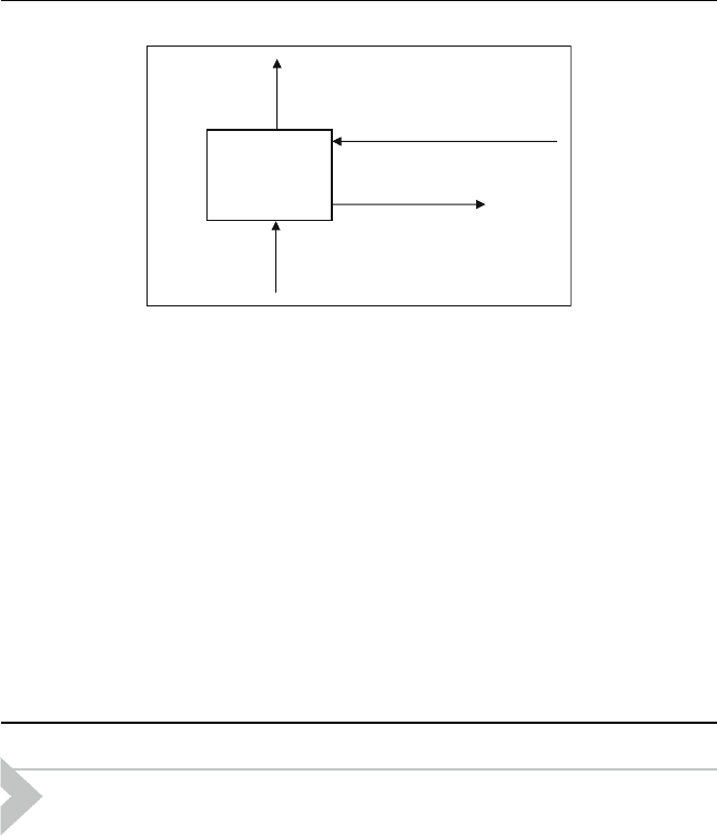
balance around the reactor unit. Assume a conversion of 75 LV%. Figure E8.1
shows the reactor input and output streams.
Solution:
AGO ¼ 20000 (bbl/day) 318.6 (lb/bbl) (1 day/24 h) ¼ 265,000 lb/h
VGO ¼ 15000 (bbl/day) 338 (lb/bbl) (1 day/24 h) ¼ 211250 lb/h
S in AGO ¼ 265000 0.2/100 ¼ 530 lb/h
S in VGO ¼ 211250 0.35/100 ¼ 739 lb/h
S in feed ¼ 1269/476250 100 ¼ 0.266%
Conversion ¼ ((Vol. of feed – Vol. of cycle stock)/Vol. of feed) 100 ¼ 75%
Cycle stock ¼ unconverted portion below gasoline ¼ (LCG + HCGO) ¼ 25
API of mixture:
Total feed ¼ 476,250 lb/h
SG for AGO ¼ 0.9099 and SG for VGO ¼ 0.9659
Then SG for mixed feed ¼
20000
20000 þ 15000
ð0:9099Þþ
15000
20000 þ 15000
ð0:9659Þ
¼ 0:9339
Products
AGO + VGO + Steam
Spent
Catalyst
Regenerated
Catalyst
R
Steam
Gases
C
3
/C
3
=
C
4
/iC
4
/C
4
=
Gasoline
LCO
Figure E8.1 Reactor input and output streams
214 Chapter 8

This gives feed API ¼ 20.02
A summary of the feed mixture is shown in Table E8.1.1.
Using the above data and the yield correlations from Table 8.6 , the material
balance and product properties can be calculated as shown in Table E8.1.2
Table E8.1.2 Yields and properties of products
lb/h
Coke wt% 0.05356 (75) – 0.18598 (20.02)
+ 5.966975
6.3 30,004
LCO LV% 0.0047 (75)
2
– 0.8564 (75) +
53.576
15.8 81,337
Gases wt% 0.0552 (75) – 0.597 4.7 22,574
Gasoline LV% 0.7754 (75) – 0.7778 57.4 226,816
iC
4
LV% 0.0007 (75)
2
+ 0.0047 (75) +
1.40524
5.7 16,375
nC
4
LV% 0.0002 (75)
2
+ 0.019 (75) +
0.0476
2.6 7735
C
4
=
LV% 0.0993 (75) – 0.1556 7.3 22,356
C
3
LV% 0.0436 (75) – 0.8714 2.4 6230
C
3
=
LV% 0.0003 (75)
2
+ 0.0633 (75) +
0.0143
6.4 16,987
HGO wt% 100 – 75 – 15.8 9.7 46,027
SinH
2
S wt% 3.9678 (0.266) + 0.2238 1.28 289
S in LCO wt% 1.04994 (0.266) + 0.00013 0.278 226
S in HCO wt% 1.88525 (0.266) + 0.0135 0.515 237
S in Coke wt% (1269 – 289 – 226 – 237)/29,813 1.734 517
Gasoline API 0.1 9028 (75) + 0.02772 (59.1)
+ 64.08
51.4
LCO API 0.34661 (75) + 1.725715
(20.02)
8.5
Table E8.1.1 Feed properties
Stream BPD API lb/h wt% S lb S/h
AGO 20,000 24 265,000 0.2 530
VGO 15,000 15 211,250 0.35 739
20.02 476,250 1269
Fluidised Catalytic Cracking 215

8.12. Material and Energy Balances
The material and energy balance around the reactor and regenerator
can be calculated by defining the input and output streams.
8.12.1. Material Balance
8.12.1.1. Reactor Material Balance
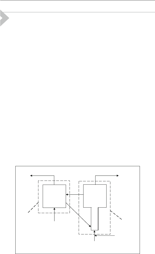
The input and output streams to the reactor (Figure 8.8) are:
Reactor input:
Oil feed (VGO) to the riser: F (BPD) or m
f
(lb/h)
Injection steam: S
in
(lb/h)
Regenerated catalyst: m
cat
(lb/h)
Reactor output:
Masses of products m
i
, as calculated from FCC yield correlations.
These correlations require some feed properties such as: API, sulphur
content and degree of severity expressed as conversion.
Spent catalyst circulation rate m
scat
(lb/h)
Steam present in cracked products, S
out
(lb/h)
Thus, a material balance around the reactor is
m
f
þ S
in
þ m
cat
¼
X
p
i¼1
m
i
þ S
out
þ m
scat
ð8:13Þ
Flue gases
Products
Feed oil
m
f
, Q
f
Air
m
air
Q
air
m
cat
Catalyst
Exothermic
reactions
Endothermic
reactions
Regenerator
T
Reg
Reactor
T
R
m
scat
∑
p
i =1
m
i
∑
n
i =1
n
i
Q
fg
Steam
S
in,
Q
s,in
Q
p
S
out,
Q
s,out
Figure 8.8 Input and output streams for reactor and regene rator in FCC unit
216 Chapter 8

where p is the total number of vapour products and assuming S
in
does
not conden se a nd is present in the exiting vapou r pr oducts at the same
rate (S
in
¼ S
out
). m
i
is the mass of each product that can be calculated
using the FCC correlations. The produced coke is pres ent in spent
catalyst. Thus
m
coke
¼ m
scat
m
cat
Equation (8.13) can be rewritten as follows:
m
f
¼
X
F
i¼1
m
i
þ m
coke
ð8:14Þ
8.12.1.2. Regenerator Material Balance
Regenerator input:
Spent catalyst circulation rate m
scat
(lb/h)
Air for coke burning m
air
(lb/h)
Regenerator output:
Flue gases n
i
(lb/h)
Regenerated catalyst m
cat
(lb/h)
Thus, the material balance around the regenerator produces:
m
air
þ m
scat
¼
X
N
i¼1
n
i
þ m
cat
ð8:15Þ
where n
i
is the mass of each gas produced from the coke burning which may
contain CO
2
, CO, H
2
O, SO
2
,N
2
and O
2
(from excess air).
8.12.2. Energy Balance
8.12.2.1. Reactor Heat Balance
Heat input:
Heat of feed oil Q
F
(Btu/h) at inlet feed temperature (T
f
)
Heat of steam injected Q
S
(Btu/h) at T
s
Heat of regenerated catalyst Q
cat
(Btu/h) at regenerator outlet temper-
ature (T
Reg
)
Heat output:
Heat in vapour products, Q
p
(Btu/h) at reactor outlet temperature
(T
R
)
Heat of spent catalyst Q
scat
(Btu/h) at T
R
Fluidised Catalytic Cracking 217

Heat of exit steam Q
s,out
(Btu/h) at T
R
Then the energy balance can be expressed as
m
f
C
p;f
ðT
f
T
o
Þþm
f
ðDH
R
Þþm
cat
C
P;cat
ðT
Reg
T
o
ÞþS
in
C
ps
ðT
s
T
o
Þ
¼ðT
R
T
o
Þ
X
m
i
C
P;i
þm
scat
C
P;scat
ðT
R
T
o
ÞþS
out
C
ps
ðT
R
T
o
Þ
ð8:16Þ
Since, m
coke
¼ m
scat
– m
cat
and S
in
¼ S
out
, then equation (8.16) becomes
m
f
C
p;f
ðT
f
T
o
Þþm
f
ðDH
R
Þþm
cat
C
P;cat
ðT
Reg
T
R
ÞþS
in
C
ps
ðT
s
T
R
Þ
¼ðT
R
T
o
Þ
X
m
i
C
P;i
þm
coke
C
P;coke
ðT
R
T
o
Þ
ð8:17Þ
8.12.2.2. Regenerator Heat Balance
Heat input:
Heat of spent catalyst Q
scat
(Btu/h) at T
R
Heat of input air for coke burning Q
air
(Btu/h) at T
air
Heat of coke combustion q
coke
(Btu/h)
Heat output:
Heat of flue gas Q
fg
(Btu/h) at T
Reg
Heat of regenerated catalyst Q
cat
(Btu/h) at T
Reg
Thus the heat balance around the regenerator can expressed as
m
air
C
p;air
ðT
air
T
o
Þþm
coke
C
P;coke
ðT
R
T
o
Þþq
coke
¼ðT
Reg
T
o
Þ
X
n
i
C
P;gi
þ m
cat
C
P;cat
ðT
Reg
T
R
Þ
ð8:18Þ
Example E8.2
Find the catalyst circulation rate for the FCC unit used in example E8.1 by
carrying out a heat balance around the regenerator. A sketch of the stream flows
and temperatures around the regenerator is presented in Fig. E8.2.1
Data:
Heat of combustion of coke, DH
C
¼0.393 10
6
kJ/kmol,
C
P,cat
¼ 1.11 kJ/kg.K,
C
P,air
¼ 29.6 kJ/kmol.K, C
P,N
2
¼ 32.6 kJ/kmol.K, C
P,CO
2
¼ 46.9 kJ/kmol.K,
C
P,coke
¼ 21.1 kJ/kg.K
Solution:
Coke produced ¼ 29,813 lb/h ¼ 13,551 kg/h (from example E8.1)
Coke ¼ 13,551 kg/h ¼ 1129 kmol/h
q
coke
¼ 1129 (kmol/h) 0.393 10
6
(kJ/kmol) ¼ 443.8 10
6
(kJ/h)
218 Chapter 8

Air required ¼ O
2
required/0.21
O
2
required:
C+O
2
! CO
2
m
O2
¼ O
2
required ¼ 1129 kmol/h
m
CO2
¼ 1129 kmol/h
m
air
¼ air required ¼ 1129/0.21 ¼ 5376 kmol/h
m
N2
¼ 5379 0.79 = 4247 kmol/h
Thus, the heat balance from equation (8.18) gives
5376 29:6ð200 15Þþm
cat
1:11 ð520 15Þþ13551 21:1 ð520 15Þ
þ443:8 10
6
¼ð700 15Þ½1129 46:9 þ4247 32:6þm
cat
1: 11 ð690 15Þ
m
cat
¼ 2.58 10
6
kg/h ¼ 43.0 t/min ¼ 0.717 t/s
8.13. Kinetic Model for FCC Reactor
The FCC process involves a network of reactions producing a large
number of components. Therefore, lumping models can be used to describe
the reaction system in terms of the feed and a defined number of products.
Three, four and up to over ten lumps can be used theoretically. A three
lump model (Figure 8.9) assumes that VGO produces two products: gaso-
line and a combined product of gas and coke, where y refers to the mass
fraction of each lump and k is the reaction rate constant.
A more realistic model is the four-lump model (Figure 8.10) in which
VGO produces gasoline, gas and coke.
Assuming that the VGO cracking rate is second order and gasoline rate is
first order. The three and four lump models in Figures 8.9 and 8.10,
respectively, are shown below. In these models the catalyst deactivation
rate f is considered equal for all reactions.
Regenerator
m
N2
, m
CO2
T
Reg
= 700 ⬚C
m
air
T
air
= 200 ⬚C
m
scat
+ m
coke
T
scat
= T
R
= 520 ⬚C
m
cat
T
Reg
= 690 ⬚C
Figure E8.2.1 Regenerator
Fluidised Catalytic Cracking 219

Three-lump model:
for VGO
r
1
¼
dy
1
dt
¼k
1
y
2
1
f k
3
y
2
1
f ¼k
1
þ k
2
ðÞy
2
1
f ð8:19Þ
for gasoline
r
2
¼
dy
2
dt
¼ k
1
y
2
1
f k
2
y
2
f ¼ k
1
y
2
1
k
2
y
2
f ð8:20Þ
for gas + coke
r
3
¼
dy
3
dt
¼ k
3
y
2
1
þ k
2
y
2
f ð8:21Þ
Four-lump model:
for VGO
r
1
¼
dy
1
dt
¼k
12
y
2
1
f k
13
y
2
1
f k
14
y
2
1
f ð8:22Þ
for gasoline
r
2
¼
dy
2
dt
¼ k
12
y
2
1
f k
23
y
2
f k
24
y
2
f ¼ k
12
y
2
1
k
23
y
2
þ k
24
y
2
f
ð8:23Þ
for gas
r
3
¼
dy
3
dt
¼ k
23
y
2
þ k
13
y
2
1
f ð8:24Þ
VGO (y
1
) Gasoline (y
2
)
Gas + Coke
(y
3
)
k
3
k
2
k
1
Figure 8.9 Three-lump model
k
12
VGO (y
1
)
Gasoline (y
2
)
Gas (y
3
)
k
14
k
23
Coke (y
4
)
k
24
k
13
Figure 8.10 Four-lump model
220 Chapter 8
