Elsevier Encyclopedia of Geology - vol I A-E
Подождите немного. Документ загружается.


The Walk-Over Survey
The walk-over survey is a detailed inspection of the
site. It is often done in stages, with an initial visit for
familiarization, photography, and checking of the
current site conditions, and subsequent visits to
check out features noted on historical maps and
photographs. Features should be sketched at an ap-
propriate scale on a base plan for inclusion in the
desk-study report.
Derelict, Reused, and Contaminated Land
The desk study may reveal that a site has a history of
previous use. Industrial use is likely to have left a
legacy of pollution, which will require identification
and possibly treatment depending on the intended
reuse of the site. Guidance on the investigation of
contaminated ground on the basis of ‘source-path-
way-receptor’ is given in the key reference documents
listed. The desk study will form an important element
of the ‘phase 1 risk assessment’ that is required by
contaminated-land legislation. An environmental
specialist will need to be consulted whenever contam-
ination is suspected, and appropriate safety precau-
tions should be taken at all stages of the investigation
work.
Reporting the Desk Study
On completion of the desk study, the results are for-
mally presented in a report that brings together details
of site topography, geology, geotechnical problems
and parameters, groundwater conditions, existing
construction and services, previous land use, expected
construction risk, and proposed ground-investigation
methods. A hazard plan is a good way of presenting
a summary of the data accumulated during the desk
study and walk-over survey.
Properties to be Determined
The prime purpose of a site investigation is gener-
ally to determine the ground profile and the continu-
ity and properties of the various strata. This will
include ranges of values and assessments of probabil-
ity and risk, so that construction may proceed within
a defined framework of knowledge.
Ground Investigation
Ground Investigation Design
The objective of a ground investigation is to ensure
economical design and construction by reducing to an
acceptable level the uncertainties and risks that the
ground poses to the project.
The initial appraisal (desk study) will identify what
is already known and will facilitate a preliminary
understanding of the ground and its behaviour. This
provides a basis for assessing the nature, location,
extent, and duration of subsequent fieldwork and
for preparing a programme of laboratory tests of
samples obtained during the fieldwork. It is the geo-
technical model against which every piece of acquired
data can be checked. As the field programme pro-
gresses, so the model will be either confirmed or
amended.
The design of the ground investigation can com-
mence only once the following information has been
obtained and client approval given:
1. a clearly defined purpose for the investigation;
2. an assessment of what information is required
and when;
3. the areas and depths of ground to be investigated;
4. the time required for the investigation; and
5. an estimate of the cost.
These items can be conveniently covered by the
Procedural Statement, as discussed previously.
Ground Investigation Methods
The ground investigation can include many different
activities such as:
.
trial pits with descriptions of the material exposed;
.
boreholes with sampling for later laboratory
testing;
.
tests in boreholes using simple or sophisticated
instruments;
.
probing from the ground surface;
.
loading tests at the surface or in excavations;
.
geophysical testing; and
.
geochemical sampling.
Ground-contamination investigations are often re-
quired, especially on derelict sites; appropriate ex-
pertise is essential as there are important health and
safety considerations.
How Many? How Deep?
The scope and size of the ground investigation will
depend both on what is known about the site and on
the nature of the project. The ground investigation
may, therefore, vary from a few trial pits dug by an
excavator in one day, for a small housing project, to a
major undertaking lasting many months, for a large
earth dam. There are often alternative approaches
that are equally acceptable technically, but sometimes
one method is preferable to the other because of
plant availability or access restraints. Boreholes
may to some extent be replaced with trial pits, cone
ENGINEERING GEOLOGY/Site and Ground Investigation 585
penetrometer probes, or geophysical surveys to pro-
vide similar or complimentary information. Cost is
always important, but the designer should prepare
the ‘right’ investigation for the project rather than
working to a fixed budget provided by the client.
Teamwork is important and involves pooling ideas
and suggestions and taking account of restraints im-
posed by the client, structural designers, auditors, or
environmental specialists, who may have valuable
input that can be used to support the geotechnical
engineer in preparing the investigation. Again, the
Procedural Statement is a useful vehicle for conveying
proposals to all interested parties.
Time should be allowed for innovative design and
review of proposals. ‘Sleeping’ on ideas for a day or
two can often lead to the development of better alter-
natives. Checklists are useful to remind the designer
of aspects that should be covered.
Guidance on spacing and depth of and sampling in
exploratory holes may be found in the publications
of the Site Investigation Steering Group and other key
texts.
There may be a temptation to believe that every-
thing about a site should be discovered at the investi-
gation stage. It may be more realistic to accept that
certain local features (for example swallow holes in
chalk, mine workings beneath a highway cutting, or
precise founding levels in variable strata) are best
picked up and reviewed during the construction or
remediation phase. This could be more cost-effective
than attempting to detect every void and strata
variation during the investigation, but it does require
an element of flexibility and the application of
appropriate expertise during the construction work.
Such flexibility is more readily available in the ‘design
and construct’ type of construction contract and in
the use of ‘observation methods’, which are gaining
popularity with clients.
Ground Investigation Fieldwork
The various approaches that might be considered for
gaining information on ground conditions are briefly
reviewed in this section.
Trial Pitting
Trial pitting is a relatively cheap and efficient method
of exploring the ground. Techniques vary from dig-
ging by hand – useful where services may be present
or access by machine is difficult – and using mini
excavators – where access is restricted – to using
large-tracked back-hoe type excavators, which can
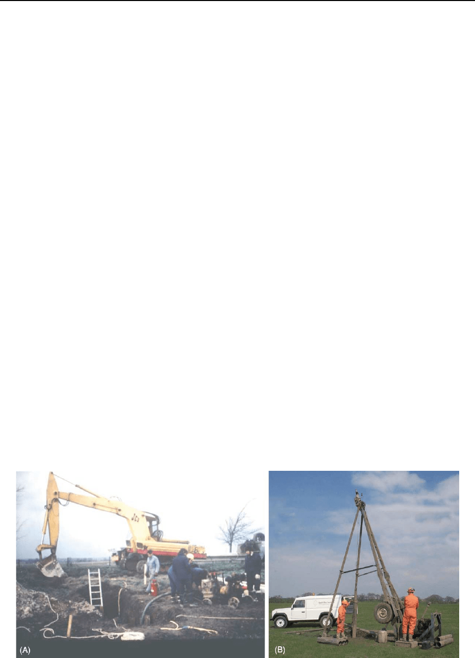
reach depths of 6 m or more (Figure 2A).
Trial pits enable the stratification and the true
nature of each soil horizon to be logged and represen-
tative samples selected. Block samples can be cut for
subsequent laboratory testing, and localized samples
can be taken from shear surfaces. However, access to
the pit for close visual inspection is permitted only
where temporary side support (shoring) is provided
and a careful assessment of the risk of instability and
the presence of gas has been made.
When inspecting the ground, a small wedge of soil
is frequently sheared away from the side of the pit to
reveal the true nature of the soil behind the zone of
smear resulting from excavation. A moisture-content
profile using close centres (typically 75 mm) can pro-
vide much information about the consistency of the
soil. This is easily and accurately undertaken using
the ‘moisture in the bag’ technique. The moisture
Figure 2 Two common methods of exploration. (A) The trial pit, with shoring and ladder for safe access and egress. (B) The
percussion boring rig.
586 ENGINEERING GEOLOGY/Site and Ground Investigation
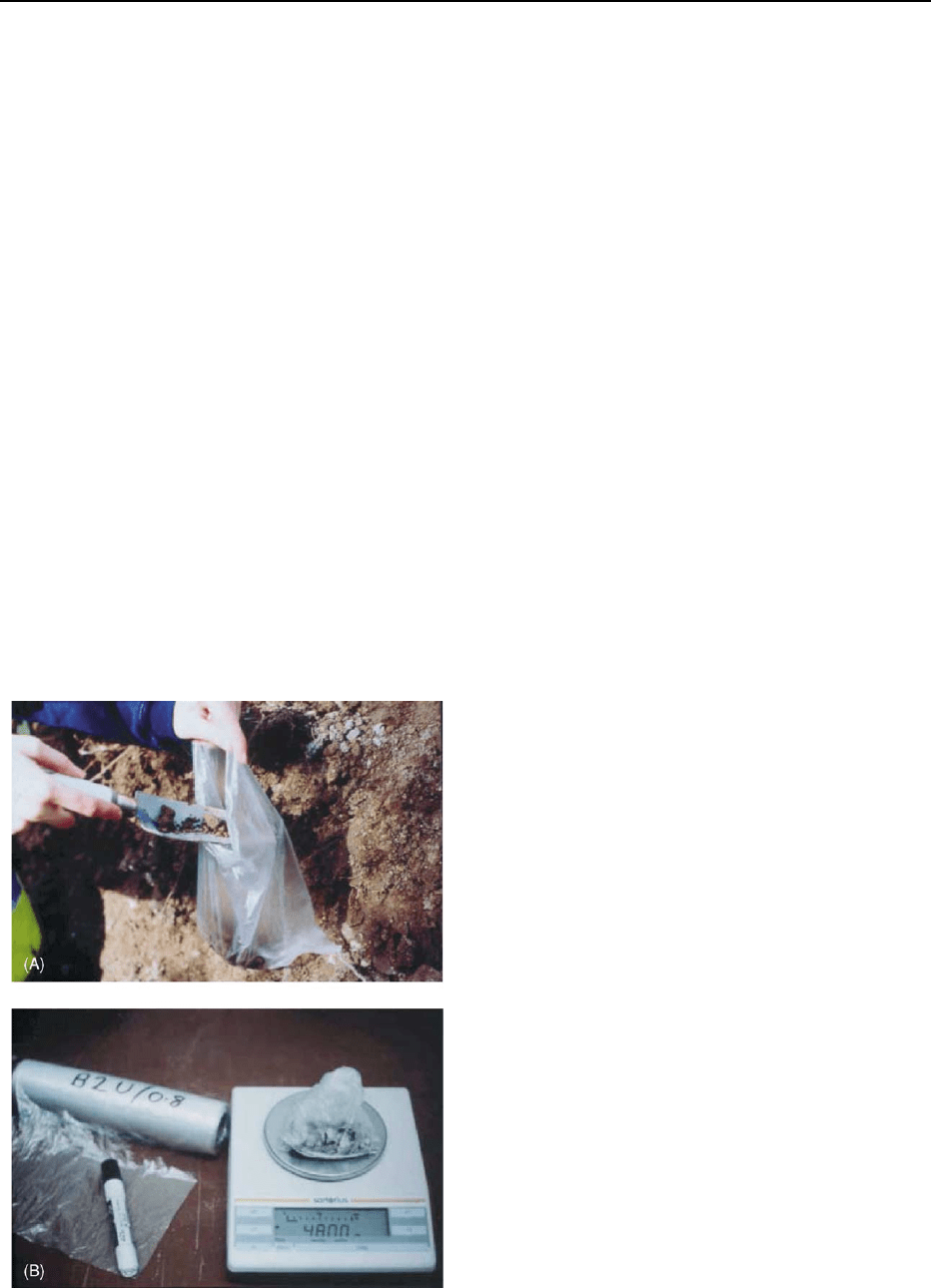
samples are sealed in a lightweight polythene bag
(Figure 3). They are then weighed and dried in the
bag, avoiding the need for separate moisture-content
containers and reducing the error due to dehydration
during sample storage.
Observation of the sides of the pit will provide an
indication of the stability of the ground. The nature of
the excavated material will provide information on
possible reuse during earthworks. If a trial pit can be
safely protected and left overnight, drying of the soil
surface often reveals fissures, discontinuities, and
possible existing slip surfaces within the strata.
Groundwater conditions and their effect on ground
stability may be closely observed in the pit. Instability
due to groundwater flow may prevent safe advance-
ment of the pit in finer-grained granular soils. Per-
meability testing (by pumping or by water addition)
may be carried out to give an indication of the ground
permeability.
On completion of the excavation, strata should be
replaced and compacted back to the depth excavated.
The location (grid coordinates) of the pit must be
carefully recorded as the ground is now disturbed
and could present a hazard to future construction.
For this reason, pits are generally excavated outside
the planned area of the proposed foundations. The
positions of exploratory holes are readily established
by modern handheld global positioning systems.
Boring Techniques – Soft Ground
The light cable tool percussion (‘shell and auger’)
technique of soft-ground boring at a diameter of
150 mm is perhaps the best-established, simplest,
and most flexible method of boring vertical holes,
particularly in the UK (Figure 2B). It generally allows
data to be obtained for strata other than rock. A
tubular cutter (for cohesive soil) or a shell with a
flap valve (for granular soil) is repeatedly lifted and
dropped using a winch and rope operated from
a tripod frame. The soil that enters these tools is
regularly removed and laid to one side for backfill-
ing. Steel casing is used where necessary to prevent
collapse of the sides of the borehole.
The technique can determine conditions to depths
in excess of 30 m under suitable circumstances and
usually causes less surface disturbance than trial
pitting.
Small disturbed samples are taken on encountering
each new stratum and at regular intervals within it.
Larger samples of the materials are taken typically at
1 m intervals in the top 5 m of the borehole and
subsequently at 1.5 m intervals. In cohesive or ‘fine
grained’ soils, sampling is by nominal 100 mm diam-
eter 0.45 m long open-tube drive sampling (U100),
and the sample is often referred to as a (relatively)
‘undisturbed’ sample. These are sealed with wax to
preserve moisture and capped at each end prior to
transport to the laboratory for testing.
In granular soils a standard penetration test (SPT)
is typically undertaken at 1 m to 1.5 m intervals,
depending on depth, and a bulk sample is removed
from the tested length for subsequent description and
classification. The SPT involves driving a 50 mm
diameter tube or cone into the ground using a 65 kg
weight falling a distance of 760 mm and controlled
using a trip mechanism. Blows are counted for
successive penetrations of 75 mm for a distance of
450 mm. The SPT value is the number of blows re-
quired to penetrate the final 300 mm. This test is
sometimes also used in firm clays. The results of the
SPT are correlated empirically with the density and
angle of shear resistance in granular soils and with
shear strength in cohesive soils.
Alternative techniques that might be considered
for advancing boreholes include the less reliable
wash-boring method, where the soil is washed out
of the cased hole, and flight auger boring, where
disturbed samples are brought to the surface by the
rotation of the auger and, where hole stability per-
mits, the auger is removed for undisturbed sampling.
Figure 3 ‘Moisture in the bag’; an efficient method of determin-
ing moisture contents.
ENGINEERING GEOLOGY/Site and Ground Investigation 587
The hollow-stem flight auger is a more reliable
system, which supports the hole whilst undisturbed
samples are recovered through the central stem.
For shallow holes where access is difficult, hand
augering may be employed. The use of a lightweight
mechanical hammer associated with dynamic probing
has led to the recent development of the ‘window’
sampling technique. This involves driving a tube with
a section of the side wall removed to allow the soil
sequence to be logged and samples to be selected from
the side for classification and, increasingly, for con-
tamination testing. Sample-tube lengths are typically
1 m or 1.5 m. Deeper sampling is possible by pro-
gressively reducing the tube diameter to reduce side
friction from the strata above the sampling level.
Boring Techniques – Hard Ground
Rotary drilling produces rock cores by rotating an
annular diamond-impregnated tube or barrel into
the ground. This is the technique that is most ap-
propriate for making investigation holes in rock or
other hard strata. It may be used vertically or at any
angle.
Core diameters of less than 100 mm are most com-
mon for site-investigation purposes. A flushing fluid
such as air, water, mist, or foam is used to cool the bit
and carry cuttings to the surface.
Examination of rock cores allows detailed descrip-
tion and generally enables angled discontinuity sur-
faces to be observed. However, it does not necessarily
reveal the presence of near-vertical fissures or joint
discontinuities. The core can be tested in the field or
in the laboratory. Core recovery depends on rock type
and the techniques employed.
Where open-hole rotary drilling is employed, de-
scriptions of the strata depend on the examination at
the surface of small particles ejected from the bore-
hole in the flushing medium. Consequently, no indi-
cation of fissuring, bedding, consistency, or degree
of weathering can be obtained. Depths in excess of
60 m can be investigated using rotary techniques with
minimal surface disturbance.
Dynamic and Static Probing
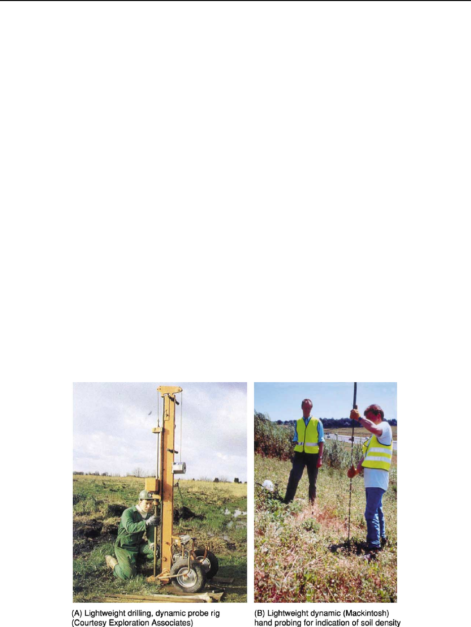
Dynamic probing involves driving a rod with a fixed or
detachable cone into the ground by allowing a falling
weight to impact on an anvil attached at the top of
the rod and counting the number of blows required
to achieve successive penetrations, typically of 100
mm. The apparatus can be handheld (for example the
Mackintosh probe), or a machine-mounted weight and
guide can be used for larger-diameter rods (for example
the Pennine probe) (Figure 4).
Figure 4 Examples of dynamic probing (A) by lightweight drilling and (B) by hand. (A) A dynamic probe rig (photograph courtesy of
Soil Mechanics). (B) Lightweight dynamic (Mackintosh) hand probing to obtain an indication of soil density.
588 ENGINEERING GEOLOGY/Site and Ground Investigation
Whilst the number of blows may be correlated
empirically with the shear strength or density of
granular soils, these are generally profiling tools best
used for interpolating between boreholes or trial pits.
Samples are not normally taken, but the technique
has been extended by using the hammer apparatus to
take ‘window’ samples, as described above.
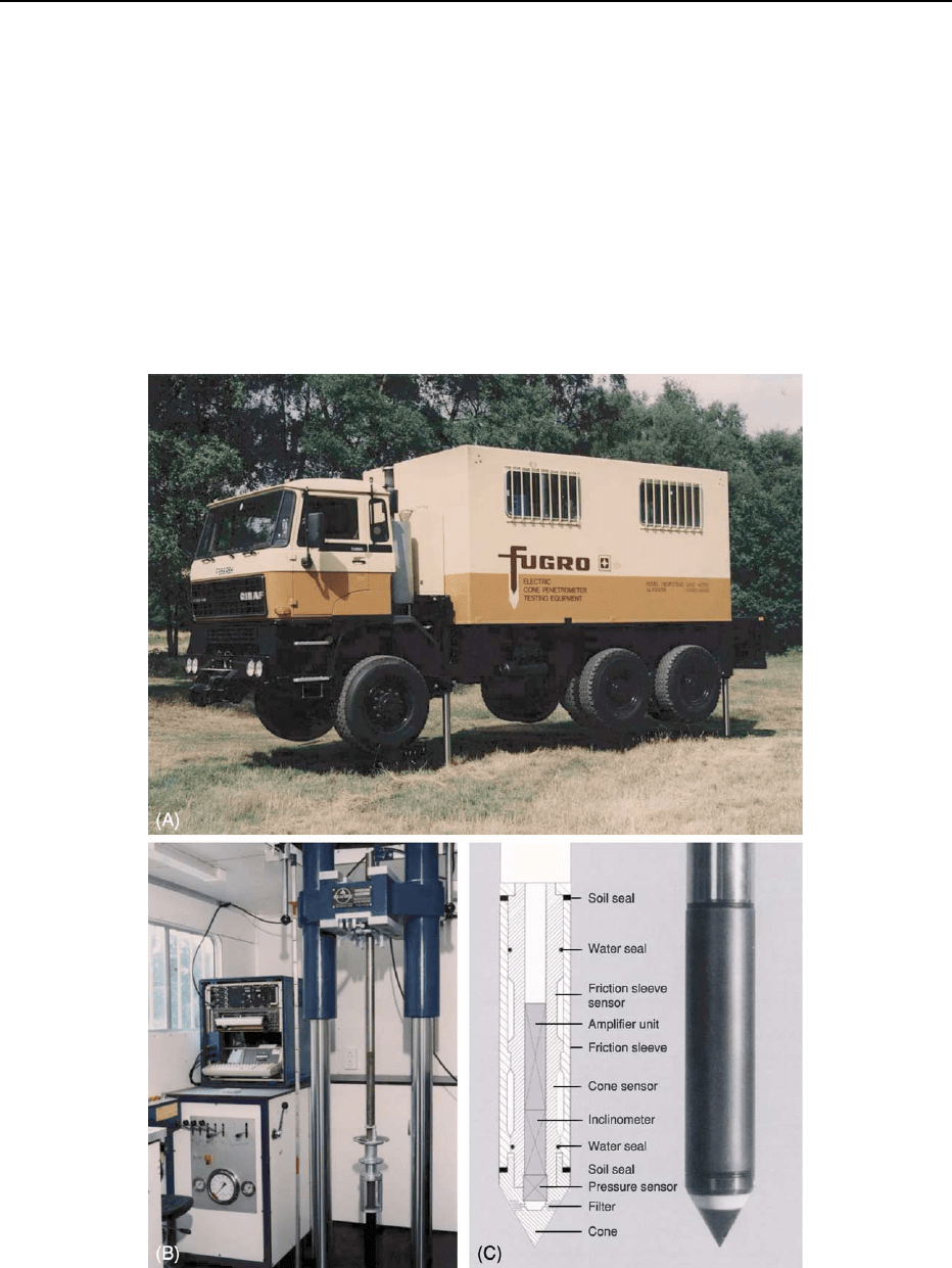
The static cone technique (Figure 5) involves push-
ing an instrumented cone and sleeve into the ground
at a defined rate and recording the point resistance
and skin friction using electronic means. More so-
phisticated instruments can now monitor the pressure
of pore water just behind the cone tip. By considering
the ratio of end resistance to shaft friction resistance,
an indication of the soil type and its density may be
deduced.
The apparatus can measure changes in soil type
over very short distances and avoids the problems of
disturbance, particularly of granular soils, below the
water table. It is a very rapid technique, often used as
a profiling tool between boreholes, and is capable
of electronic interpretation. It has been used exten-
sively in North Sea oil and gas structure foundations
and is now used widely for land-based investigations.
Figure 5 The static cone apparatus. (A) ‘Dutch’ cone penetrometer testing truck with (B) control console and (C) electric static cone
(photographs courtesy of Fugro Ltd).
ENGINEERING GEOLOGY/Site and Ground Investigation 589

As with all probing techniques, the presence of large
cobbles and boulders can prevent penetration in cer-
tain soils and in made ground. Although linked with
boring techniques, the static and dynamic cones are
regarded as a form of in situ test.
In Situ Testing
The main objectives of a ground investigation are
generally to identify and classify the soil types into
groups of materials that exhibit broadly similar en-
gineering behaviour and to determine the parameters
that are required for engineering design calculations.
Some soils, such as certain clays, may be readily
sampled and transported to the laboratory for quality
testing under controlled conditions. Other soils, such
as very soft or sensitive clays, stony soils, sands, and
gravels, and weak, fissile, or fractured rock are not
easily sampled in an intact ‘undisturbed’ state, and
therefore in situ testing is required to obtain the
necessary engineering parameters. In situ tests may
take the form of geophysical tests (as described in the
following section), in situ soil-testing techniques, or
links with field instrumentation.
In situ tests fall into three typical groups.
1. Empirical tests, where no fundamental analysis is
possible and stress paths, drainage conditions, and
rate of loading are either uncontrolled or inappro-
priate (example is SPT).
2. Semi-empirical tests, where a limited relationship
between parameters and measurements may be
developed (examples are cone penetrometer tests,
California Bearing Ratio (CBR) and borehole per-
meability tests).
3. Analytical tests, where stress paths are controlled
(but strain levels and drainage often are not)
(examples are vane shear strength, pressuremeter
tests, pumping tests and packer permeability).
Details of the tests and their application are
given in British Standards 1377 and 5930 and other
references listed in the further reading section. The
main point to note with in situ testing is that the
drainage conditions are almost impossible to
control, and, therefore, there is uncertainty as to the
drained/undrained nature of the test. However, the
very act of testing in situ provides a good indication
of the actual ground response provided that scale
factors are taken into account. For example, a plate-
load test having a plate width of B will affect the
ground to a depth of approximately 1.5B. The actual
foundation may be many times the width of the test
plate, and the depth of influence will therefore be
much deeper.
The SPT is a simple cost-effective means of assess-
ing granular soils. More analytically correct tools
such as the pressuremeter are expensive and their
results are not always straightforward to interpret.
Judgement must be used to determine the level of
sophistication required for a particular project.
Geophysical Investigation
Measurement of the geophysical properties of the
ground may provide an indication of the location of
strata boundaries and anomalous ground conditions.
Such surveys may include measurements of ground
conductivity, magnetic and gravity fields, electrical
resistivity, and seismic responses (see Analytical
Methods: Gravity, Seismic Surveys).
The use of geophysical techniques is generally
non-intrusive, with little site disturbance, and is
therefore sometimes carried out at the desk-study
stage. However, the main benefit comes when some
exploratory hole data are available to permit more
accurate calibration, correlation, and processing of
the geophysical data. The ability of the current
generation of computers to process large amounts
of data rapidly has led to a resurgence of interest in
the potential value of geophysical investigation
techniques.
Groundwater and Instrumentation
The presence of groundwater leads to many engineer-
ing problems, and it is vital that all water observa-
tions are carefully recorded. Whenever water is struck
in a borehole or trial pit the point of entry must
be noted. It is normal practice to cease the advance-
ment of the hole for 20 min whilst any rise in the
water level is observed. Longer-term observations of
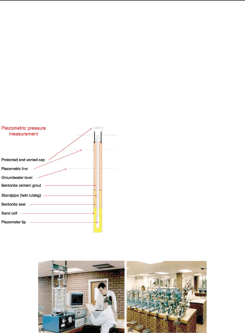
groundwater fluctuations may be made by instal-
ling a standpipe or standpipe piezometer. This
typically comprises a porous filter at the base of a
19 mm diameter plastic tube inserted to an appropri-
ate depth in a borehole (Figure 6). Water enters
through the porous filter, and its level in the plastic
tube can be monitored over a period of time using a
dip meter that emits an audible signal when an elec-
trical circuit is completed as it meets the water in the
borehole.
Water-level records taken over an appropriate
period of time will reveal the likely range of water
conditions to be allowed for in the design and to be
encountered during the project construction.
More sophisticated equipment such as hydraulic,
electrical, or pneumatic piezometers with trans-
ducer systems and automatic recording can be used
590 ENGINEERING GEOLOGY/Site and Ground Investigation
where the information obtained is critical to the
project.
Other instrumentation, such as settlement gauges,
plates, and extensometers to measure vertical move-
ment, and slip indicators and inclinometers to meas-
ure lateral movement at depth, are available for use
in conjunction with the ground investigation or
with advance trial constructions and main works
constructed by ‘observational’ methods.
Laboratory Testing
It should be remembered that soil is an assemblage
of solid particles, which may contain organic matter.
The voids between the particles are filled with gas –
usually air – and water. The geotechnical engineer
will need to determine the composition of the
ground in situ and also explore the changes that
will occur to the soil as a result of the proposed
construction.
Laboratory tests tend to be divided into two main
classes.
Classification tests involve grouping soil types into
categories of soils that possess similar properties. For
coarse-grained soils the particle size distribution is
often the key property, whereas for fine-grained soils
the moisture content and mineralogy, as reflected in
the Atterberg limits (index properties), most often
hold the key to grouping soils of similar characteris-
tics. For general classification purposes, the moisture
content and index properties (liquid limit, plastic
limit, and sometimes shrinkage limit) are used to-
gether with the particle size distribution, density of
the soil, and, most importantly, an accurate descrip-
tion carried out in accordance with the standards in
the code of practice.
Engineering tests assess the engineering properties
of the soil, such as routine shear strength, compress-
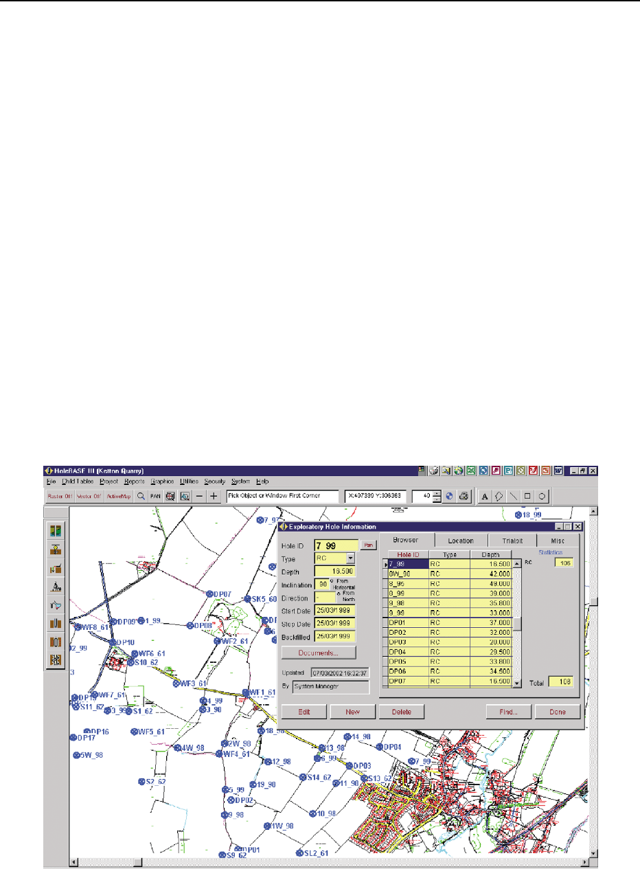
ibility (see Figure 7), compaction characteristics, and
permeability. Where more specific soil properties are
required for complex design functions, ‘advanced’
laboratory tests may be used, in which high-quality
undisturbed samples are carefully prepared and tested
under precise laboratory control and stress and small
strains are measured.
Full details of laboratory tests and their relevance
to engineering design are given in the appropriate
British Standards and the key references in the further
reading section.
It is important that the testing regime is planned in
advance of the fieldwork in order that suitable
samples are recovered from the ground. The Proced-
ural Statement will help with this planning process,
as the reasons for the sampling and subsequent
Figure 7 Commercial laboratory testing for shear strength and consolidation. (A) A 100 mm triaxial test cell. (B) A bank of consoli-
dation (oedometer) test machines. (Photographs courtesy of CSL Ltd.)
Figure 6 Schematic of standpipe piezometer (courtesy of
Geotechnical Instruments UK Ltd).
ENGINEERING GEOLOGY/Site and Ground Investigation 591
laboratory testing can be logically considered to-
gether with the significance of the anticipated results.
Reporting
The reporting of site and ground investigation work is
most important. The factual report is generally the
only tangible output from the investigation and
represents a considerable financial investment. The
factual report should include:
.
a statement as to the purpose and rationale of the
investigation;
.
a description of the work carried out, including
references to the specification and standards
adopted and any deviations from them;
.
exploratory hole logs (including location and
ground level);
.
in situ test records;
.
laboratory test results; and
.
a site location plan.
The development by the Association of Geotech-
nical and Environmental Specialists of a standard
format for geotechnical data files in digital form has
led to the efficient collection, transfer, processing,
presentation, and storage of the data for all parties
involved in the investigation process. Data are ideally
input manually to the computer only once or are
collected directly in electronic form from monitoring
and testing devices. Specialist software houses have
developed programs to help the investigator collect,
store, and process the data and to present it in the
form most suited to the requirements of a particular
project (Figure 8).
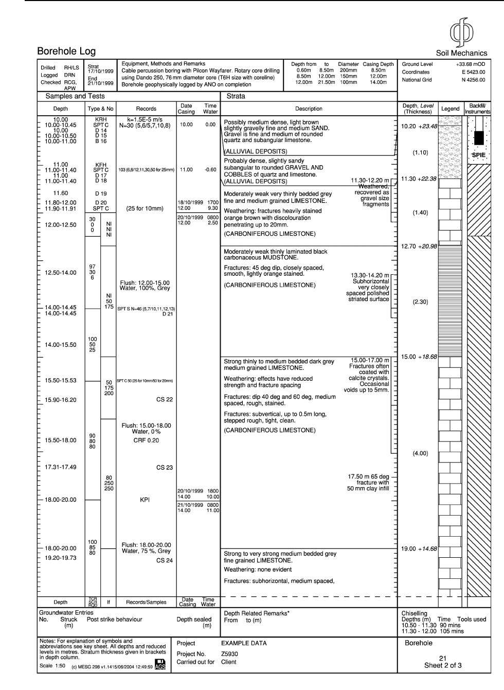
The exploratory hole log can perhaps be regarded
as the heart of the factual report because it records
all the information obtained at that particular loca-
tion. An example log prepared from digital data is
presented in Figure 9.
Interpretation of the geotechnical data to relate
them to the proposed design and construction will
be required for each project and is normally the re-
sponsibility of the Geotechnical Advisor. Formal in-
terpretive reports (also known as assessment reports
or appraisal reports) may be prepared as required by
the design team. It is good practice to prepare a
Figure 8 Use of digital techniques for efficient handling of site investigation data (image courtesy of Key Systems and Geotechnical
Developments).
592 ENGINEERING GEOLOGY/Site and Ground Investigation
f0045 Figure 9 Example exploratory hole log (Courtesy Soil Mechanics).
ENGINEERING GEOLOGY/Site and Ground Investigation 593

geotechnical design brief to assist the construction
team on site and, at the end of the project, to prepare
a feedback (maintenance) report on any issues from
which lessons can be learned and on which future
scheme development can be based.
The various stages of quality control and reporting
that help to ensure maintenance of the standards and
accuracy of the output from a site and ground investi-
gation are described in the publications of the Site
Investigation Steering Group.
Concluding Remarks
Site investigation involves establishing facts concern-
ing the ground; the excitement of discovery is
tempered by the professional responsibility for much
of the financial risk and safety associated with each
engineering project.
The combination of appropriately experienced in-
vestigators working to agreed team procedures within
a sensible permitted time frame with limited compe-
tition is likely to produce the best solutions to engin-
eering challenges presented by particular ground
conditions. This article has touched on some of the
important issues relevant to site investigation but is in
no way intended to be a complete guide. A good
investigator will set out to define the investigation
but to expect the unexpected.
See Also
Analytical Methods: Gravity. Engineering Geology:
Codes of Practice; Site Classification; Ground Water
Monitoring at Solid Waste Landfills. Geotechnical En-
gineering. Seismic Surveys. Soil Mechanics.
Further Reading
BS 5930 (1999) Code of Practice for Site Investigation.
London: BSI.
BS 1377 (1990) British Standard Methods of Test for Soils
for Civil Engineering Parts 1–9. London: BSI.
BS 10 (2000) Contaminated Land. London: BSI.
BS 10175 (2001) Investigation of potentially contaminated
sites. London: BSI.
Clayton CRI, Matthews MC, and Simons NE (1995) Site
Investigation: A Handbook for Engineers, 2nd edn.
Oxford: Blackwell Scientific.
HD22/02 Managing geotechnical risk. DMRB. London:
Highways Agency.
Institution of Civil Engineers (2003) Conditions of Con-
tract Ground Investigation, 2nd edn. London: Thomas
Telford.
McCann DM, Eddlestone M, Fenning PJ, and Reeves GM
(eds.) (1997) Modern Geophysics in Engineering. Special
Publication 12. London: Geological Society.
Perry J (1996) Sources of Information for Site Investiga-
tions in Britain. TRL Report 192. Crowthorne: Transport
Research Laboratory.
Simons N, Menzies B, and Matthews M (2002) A Short
Course in Geotechnical Site Investigation. London:
Thomas Telford.
Site Investigation Steering Group (1993) Part 1: Without
Site Investigation Ground is Hazard. London: Thomas
Telford.
Site Investigation Steering Group (1993) Part 2 Planning,
Procurement and Quality Management. London:
Thomas Telford.
Site Investigation Steering Group (1993) Part 3 Speci-
fication for Ground Investigation. London: Thomas
Telford.
Site Investigation Steering Group (1993) Part 4 Guidelines
for Safe Investigation by Drilling of Landfills and Con-
taminated Land. London: Thomas Telford.
594 ENGINEERING GEOLOGY/Site and Ground Investigation
