Douce A.P. Thermodynamics of the Earth and Planets
Подождите немного. Документ загружается.


298 Phase equilibrium and phase diagrams
An examination of the diagrams on the right-hand side of Fig. 6.2 shows that not all
intersections between Gibbs free energy functions correspond to stable univariant assem-
blages. For example, at Z = Z
1
, intersection 1 corresponds to the univariant assemblage
BC, but this assemblage has higher Gibbs free energy than A at the same conditions, and
intersection 3 corresponds to the univariant assemblage AC, but this has higher Gibbs free
energy than B at the same conditions. The two intersections, 1 and 3, are said to correspond
to metastable univariant equilibria. What this means is that univariant equilibrium among
the corresponding phases is possible, and may in some cases persist for extended periods
of time, but, given the appropriate activation energy (Chapter 12, recall also our discussion
of the Hindenburg in Chapter 5) the system will collapse to the stable lowest free energy
state. The lowest Gibbs free energy state in this example corresponds to stable divariant
equilibrium assemblages, which are in this case the single-phase assemblages A and B rel-
ative to the metastable univariant assemblages BC and AC, respectively. We can also see
that at Z > Z
i
phase C is never stable, and the only possible stable univariant equilibrium
assemblage is AB. The same line of argument shows that at Z < Z
i
all three phases can be
stable, univariant assemblagesAC and BC can both be stable, but univariant assemblage AB
is always metastable. Most importantly for the construction and analysis of phase diagrams,
note that all three univariant equilibria switch from stable to metastable when they cross
the invariant point.
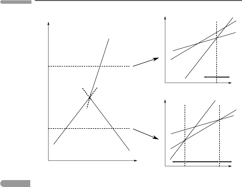
A phase diagram such as that on Fig. 6.2 is not satisfactory, as it does not convey the
fundamental difference between stable and metastable equilibria. A better representation
of the phase relations in this system is given by the phase diagram in Fig. 6.3. The stable
univariant equilibria are shown with long solid lines and their metastable extensions across
the invariant point with short broken lines. The importance of showing these metastable
extensions will become clear in the next section. The divariant fields can in this case be
uniquely identified with the name of the single phase that is stable in each of them but, as we
shall see, this is not true of systems of more than one component. In contrast, there is a simple
way of labeling the univariant curves, by using the identity of the single phase that is absent
along each univariant curve. This carries over to systems of any number of components.
For example, the curve that represents univariant equilibrium between phases A and B will
be called the C absent curve, and is symbolized by placing C inside parentheses at the end
of the curve, as shown in Fig. 6.3. This apparently innocent labeling system constitutes a
powerful tool in the construction of phase diagrams, which we will examine in the next
section. Here we note that the metastable extension of each univariant curve enters the
divariant stability field of the phase that is absent along that curve. This is a necessary
consequence of the monotonicity of the Gibbs free energy function, as you can verify for
yourself by comparing the Z–Y diagram with the G–Y diagrams in Fig. 6.3. There is a more
general way of stating this property of metastatble extensions, easily applicable to systems
of any number of components, which is that the metastable extension of each univariant
curve enters the only divariant field in which the phase absent along the univariant curve
appears as a reactant on the two univariant curves that bound the field. Thus, the metastable
extension of the (A) curve enters the only divariant field which is bound by univariant
curves in which A appears as a reactant (see Fig. 6.3).
6.2.2 Schreinemakers’ rule
Although it is possible to carry out an analysis such as that in the preceding section for
systems of more than one component, the number of assemblages and Gibbs free energy
299 6.2 Analysis of phase equilibrium
C
Z
1
Z
2
Z
Y
G
G
C
B
A
A
C
B
1
2
3
4
5
6
2
6
4
Y
AC
Y
AB
Y
CB
Y
Y
BA
(C)
(A)
(B)
B stable
A stable
B stable
A stable C stable
AB
AC
CB
Fig. 6.3
Same as Fig. 6.2, distinguishing between stable and metastable segments of the univariant curves. Intersections 2, 4
and 6 are stable univariant equilibria, because they have the lowest Gibbs free energy for the given values of Z and Y.
Intersections 1, 3 and 5 are metastable univariant equilibria. In every case a divariant assemblage with lower Gibbs
free energy exists.
curves becomes quickly unmanageable. Notice, for example, that although in the neighbor-
hood of an invariant point the plane is always divided by the c +2 univariant curves into
c +2 divariant fields, this does not mean that there are c +2 different divariant assemblages.
Except for the case c = 1, there are more. To see why, we note that in the same way that we
generate a univariant assemblage by omitting one phase from those present at an invariant
point, we can generate a divariant assemblage by omitting one phase from those present
along a univariant curve. Since there are c +1 phases in a univariant assemblage, there must
be c + 1 divariant assemblages “radiating” away from each of the c + 2 univariant curves.
This leads to a total of (c + 1)(c + 2) divariant assemblages, but each of these assemblages
is duplicated, as interchanging the order in which the two phases are omitted leads to the
same exact assemblage. Thus, the number of divariant assemblages is 1/2(c + 1)(c + 2).
For c = 1 this yields three divariant assemblages, in agreement with what we saw in the
previous section. In that case there is one and only one assemblage in each divariant field,
but for c = 2 there are six divariant assemblages distributed over four divariant fields, for
c = 3 there are ten divariant assemblages distributed over five divariant fields, and so on.
How are we to represent a system with such complexities on a two-dimensional diagram?
Fortunately, there is a simple and clever way, which arises from the work, almost a century
ago, of the Dutch physical chemist F.A.H. Schreinemakers (see, for example, the 1965
300 Phase equilibrium and phase diagrams
ZZ
ZZ
Y
(A)
(B)
(A,B)
B
A
1
2
(a) (b)
(A)
(B)
(A,B)
B
A
(C)
(B,C)
(A,C)
B
A
C
C
(c) (d)
(A)
(B)
(A,B)
B
A
(C)
(B,C)
(A,C)
B
A
C
C
(C,D)
(A,D)
(D)
(B,D)
A
C
B
D
D
D
(A)
(B)
B
A
(C)
B
A
C
C
(D)
A
C
B
D
D
D
Y
Y
Y
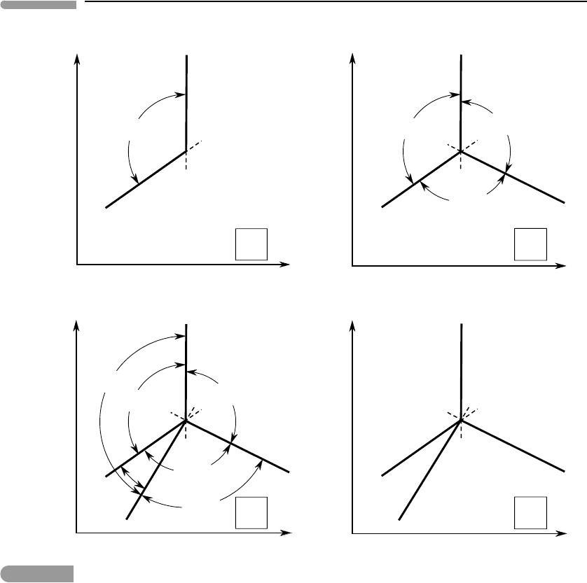
Fig. 6.4
Justification of Schreinemakers’ rule. Phases in parentheses are absent along the corresponding univariant curve or
inside the divariant field (or fields) spanned by the arc segments with arrow heads. See text for complete explanation.
English translation of his collected papers). The method is remarkably sophisticated and
leads to many possible variants of phase diagrams, which we will not review in detail
as there are clear and complete treatments available in the literature (especially those by
Korzhinskii, 1959, and Zen, 1984). The fundamental principle of Schreinemakers’ method
is, however, very simple and readily explained. We will use it repeatedly in the construction
of different types of phase diagrams. In fact, we have already deduced an important part of
the method in the preceding section, as we shall now see.
Let us consider a system with c > 1 (the actual value of c is not important for now),
and two univariant curves, which we shall label (A) and (B), see Fig. 6.4a. Divariant fields
radiate from both univariant curves. In particular, the (unique) divariant field in which
both of these phases are absent, which we can label (A, B), radiates from both of these
univariant curves. Without a formal demonstration, I will make the intuitively acceptable
statement that, just as a univariant curve switches from stable to metastable when it crosses

301 6.2 Analysis of phase equilibrium
the invariant point, a divariant field switches from stable to metastable when it crosses a
univariant curve (see, for example, Zen, 1984). Thus, the divariant field (A, B) is stable on
one side of each of the univariant curves and metastable on the other. We can see from Fig.
6.4a that it must be stable on the side of the intersection in which the angle between the
two curves is less than 180
◦
, which is shown in the figure by the arc labeled (A, B). To see
why this must be the case let us assume that (A, B) was stable on the other side, i.e. to the
right of (A) and below (B). If this were the case then we would run into the contradiction
that between each stable curve and the metastable extension of the other one, in regions 1
and 2, (A, B) would have to be simultaneously stable and metastable. This is, essentially,
Schreinemakers’ rule: a stable divariant field always extends between the two univariant
curves that each lack one of the two phases absent from the divariant assemblage, and on
the side in which the angle between the curves is less than 180
◦
(there is a special case in
which the angle equals 180
◦
, which we discuss later). This simple rule makes it possible
to construct phase diagrams of arbitrary complexity. Remarkably, it can be stated in even
simpler terms. To see how, we note that, if (A, B) is stable to the left of (A) and above (B),
then all divariant fields that are stable to the right of (A) must contain B, and all divariant
fields that are stable below (B) must contain A. Thus, A and B must show up as reactants on
the sides of the univariant curves opposite to the (A, B) field, as shown in Fig. 6.4a – this is
of course the same conclusion that we reached in Section 6.1.1 for a one-component system.
Let us now add a third univariant curve, labeled (C). Following the same arguments as
above, we label the stable divariant fields and add the reactant phases on the opposite sides
of the univariant curves, as shown in Fig. 6.4b. It appears that we have recovered the phase
diagram from Fig. 6.3, and if this was a one component system that would be the case. In
general, however, this may be only the beginning in the construction of a phase diagram
for a system with c > 1. We can add a fourth univariant curve, labeled (D), for example
as in Fig. 6.4c. Repeating the same arguments we conclude that the identities of the stable
divariant fields and the sides on which the reactant phases plot must be as shown in this figure
(note that if we had placed the fourth curve anywhere else the diagram would be identical,
except for a rotation and some switched divariant field labels). We could keep going, but
there is little reason to do so, as Schreinemakers’method already emerges from this example.
Figure 6.4c is a thermodynamically feasible phase diagram for a system of two com-
ponents. It shows consistent relative locations of all four univariant assemblages and all
six divariant assemblages. Two of the latter, (A, D) and (B, C), extend over more than one
divariant field, and there are three divariant fields that can contain more than one equilibrium
divariant assemblage. Which is the actual equilibrium assemblage in each divariant field
depends on the bulk composition of the system, as we shall see in the following section. The
labels for the divariant assemblages, and the arcs showing their extents, are not normally
shown in phase diagrams, as there is a more compact way of showing this information
(Section 6.2.3). We can thus “clean” the diagram and obtain Fig. 6.4d, which shows how
Schreinemakers’“180
◦
rule” transforms into a rule that is much simpler to apply, regardless
of how many components the system has. This is simply a restatement of the rule that we
inferred for the case c = 1, which we now see is true in general: the metastable extension
of each univariant curve enters the only divariant field in which the phase absent along the
univariant curve appears as a reactant on the two univariant curves that bound the field.
Thus, the metastable extensions of (B) and (D) enter the same field, as B and D are reactant
phases on the two boundaries of this field. The metastable extensions of (A) and (C) enter
different divariant fields, with A and C as reactant phases on their respective boundaries.
In the divariant field bound by (B) and (D) there is no phase that appears as a reactant on

302 Phase equilibrium and phase diagrams
both boundaries and, correspondingly, there are no metastable extensions going into this
field.
Schreinemaker’s rule can be stated in several equivalent ways, but I find the statement
written in italics in the preceding paragraph the one that is most generally applicable and
simplest to use. The rule determines the order in which univariant curves and divariant
fields succeed one another around an invariant point, and is all that one needs to place them
in the correct sequence. Schreinemakers’ rule is a powerful aid in the construction of phase
diagrams for phases of fixed composition, but it is equally important to understand what it
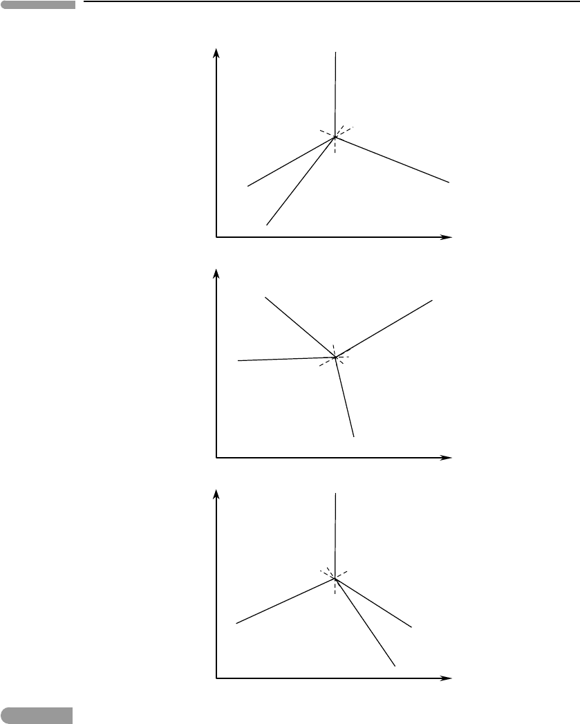
is that this method does not do. In particular, Schreinemakers’ rule does not yield: (a) the
actual slopes of the univariant phase boundaries and (b) the side of the phase boundary
on which the reactant phases appear. This is shown in Fig. 6.5. The first phase diagram
in the figure is the one that we constructed in Fig. 6.4. The second one is a rotation of
the first, and shows that changing the slopes (case (a)) does not affect the thermodynamic
validity of the phase diagram. The third phase diagram is a mirror reflection of the first
one, and exemplifies situation (b): reactant phases appear on the opposite side of each
phase boundary, and the univariant curves and divariant fields follow one another in the
opposite direction around the invariant point, relative to Fig. 6.4, yet the phase diagram
is equally feasible from a thermodynamic point of view. All three phase diagrams comply
with Schreinemakers’ rule, so they are all thermodynamically feasible, yet only one can be
correct. Deciding which is the correct phase diagram requires thermodynamic data, as we
shall see (review Exercise 6.4).
6.2.3 Chemography
We saw that, except for the case c =1, there are always more possible divariant assemblages
than there are divariant fields in the neighborhood of an invariant point. This means that in
at least some of the divariant fields more than one assemblage is possible. If we examine
the univariant reactions in the phase diagram in Fig. 6.4 or 6.5, we see that these phase
relations are possible only if there are some specific compositional relationships among
the phases. In particular, whereas phases A and C can be formed by combining subsets of
the other phases, this is not true of phases B and D. For example, we can write reactions
of the form C + D → A and B + D → C, but similar reactions in which B or D appear
by themselves on one side of the reaction do no occur. This means that B and D must be
at the ends of the compositional range of the system of interest, and that between the two of
them they span this compositional range. The chemical compositions of B and D can thus
be taken as system components (Section 6.1.2), which we will label 1 and 2, respectively.
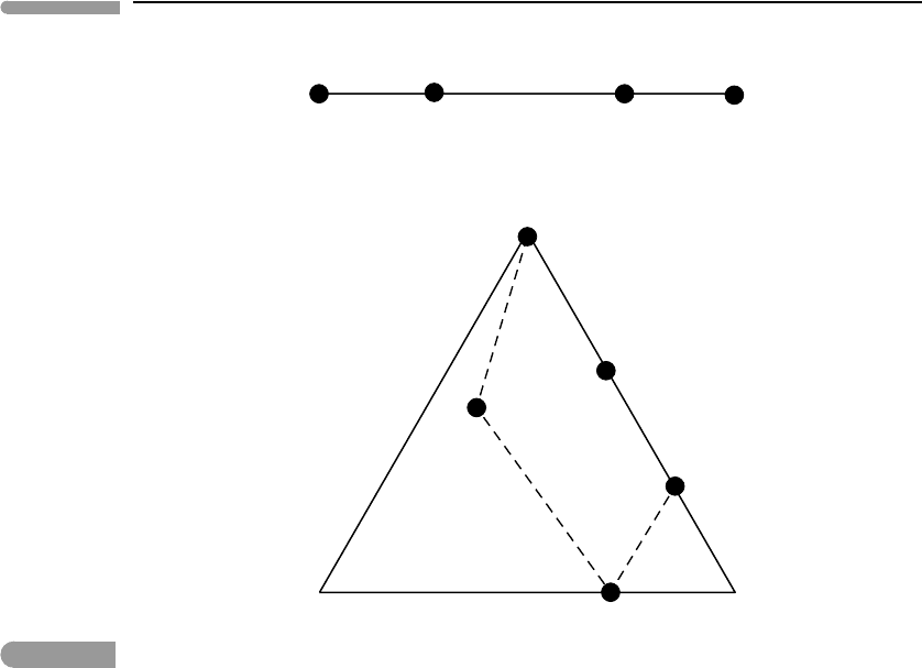
It is often helpful to show the compositional information of a system graphically (obvi-
ously, in the case of phase diagrams with phases of variable composition, it is mandatory).
This is known as chemography, and two examples are shown in Fig. 6.6. Compositional
information in a system of two components, also known as a binary system, can be repre-
sented on a line segment, in which the two system components correspond to the endpoints.
We shall write the names, or chemical compositions, of the system components below the
line (top part of Fig. 6.6). In binary systems the compositions of two of the phases of inter-
est coincide with those of the system components, and other phases are located along the
line segment. We show phase compositions with black circles, and the name of the phase
above the circle. The top part of Fig. 6.6 is an example of a chemographic diagram for a
binary system. Compositional relations in three-component, or ternary, systems are shown
on triangular chemographic diagrams such as that in the lower part of Fig. 6.6. In this case
303 6.2 Analysis of phase equilibrium
Z
Y
(A)
(B)
B
A
(C)
B
A
C
C
(D)
A
C
B
D
D
D
Z
Y
(A)
(B)
B
A
(C)
B
A
C
C
(D)
A
D
D
D
C
B
Z
Y
(A)
(B)
B
A
(C)
B
A
C
C
(D)
A
C
B
D
D
D
Fig. 6.5
Three possible phase diagrams for a binary system. The middle diagram is a rotation of the top one, the bottom one is
the mirror image of the top one. All three are thermodynamically valid.
the system components are generally located at the vertices. There may be phases whose
compositions correspond to those of some system components (e.g. E in the lower part of
Fig. 6.6). Other phases plot either on the sides of the triangle or inside it. There are many
possible variants in the arrangement of phases in three-component systems, which we will
304 Phase equilibrium and phase diagrams
1
1
3
B
CD
E
F
G
A
H
2
2
A
Fig. 6.6
Chemographic diagrams for a binary system (top) and a ternary system (bottom). Components are labeled with
numbers, phase compositions are shown with dots, and labeled with letters.
not review systematically here but will rather discuss as the need arises (see Zen, 1984, for
a systematic discussion). The arrangement of phases in the lower part of Fig. 6.6 is just an
example. The bulk composition of a system in which the phases of interest are A EFGH
must plot inside the area defined by the dotted line and the segment EG of the side 32 of
the triangle. In this case there is no set of three phase compositions that can serve as system
components, but such may be the case in other systems. Chemographic diagrams for systems
of more than three components require multiple projections from three or more dimensions
onto two. They are generally confusing and, in my view, tend to hinder understanding rather
than help it (in other words, I will not use them).
We now revisit the phase diagram in Fig. 6.4 armed with the appropriate chemographic
diagrams (Fig. 6.7). Within each divariant field we place a version of the diagram that
shows which are the phases that are stable in that field. The univariant reactions mediate
the changes between chemographic diagrams in adjacent divariant fields. For example,
univariant reaction (C), which the phase diagram shows to correspond to B +D →A, causes
A to appear between B and D in the chemographic diagrams, as the curve is crossed in the
direction of decreasing Z. The reason for using chemographic diagrams now becomes clear:
they unequivocally show which are the possible divariant assemblages in each divariant
field. For example, in the field bound by the curves (C) and (D) the two possible assemblages
are AB and AD. This information is also available in Fig. 6.4c, as assemblage (B, C) is the
same as AD, and (C, D) is the same as AB, but using a chemographic diagram shows this
information more compactly. More importantly, the chemographic diagram shows that the
identity of the divariant assemblage is determined by the bulk composition of the system,
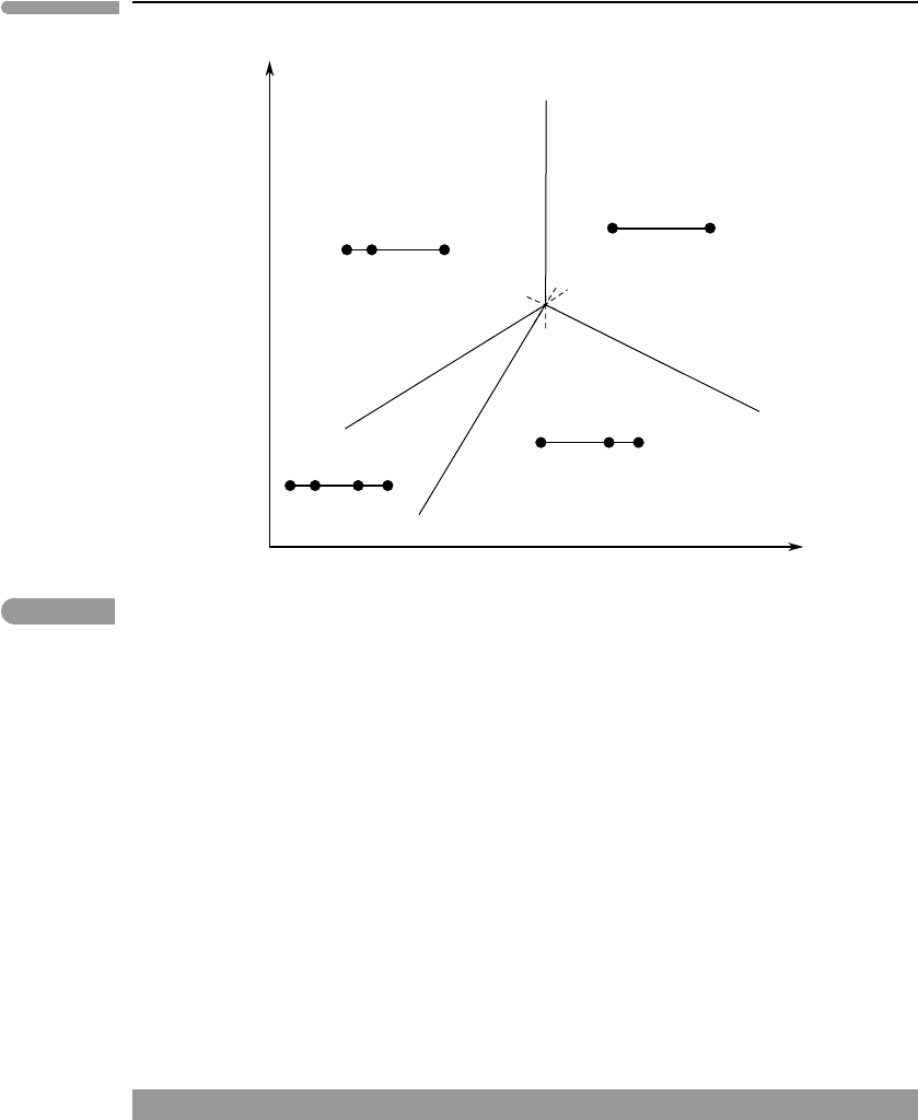
305 6.2 Analysis of phase equilibrium
Z
(A)
(B)
B
A
(C)
B
A
C
C
(D)
A
C
B
D
D
D
Y
1
2
DB
1
2
DBA
1
2
DBAC
12
DBC
Fig. 6.7
Phase diagram for the binary system shown in Fig. 6.4. The chemographic diagrams show the possible stable divariant
assemblages in each divariant field. For example, the possible divariant assemblages in the field bound by the curves
(D) and (C) are BA and AD, depending on bulk composition. The chemographic diagrams contain the same
information as the arc segments in Fig. 6.4, and in addition they show the relationship between stable assemblage
and bulk composition.
as AB or AD will form depending on whether the bulk composition is on one or the other
side of A. This information is not present in Fig. 6.4c.
There is some redundancy of information in Fig. 6.7, and as we shall see in some cases it is
not necessary, or even meaningful, to include the chemographic diagrams. If chemographic
diagrams are used, then there is an alternative way of expressing Schreinemakers’s rule,
which is that the metastable extension of each univariant curve enters the divariant field in
which the phase absent along the curve is stable for all bulk compositions. You can verify
the validity of this statement in Fig. 6.7. This version of the rule is easy to apply in systems
of two and three components, but can be (very) tricky when c > 3. In all cases I prefer the
statement given in Section 6.2.2, which is equally easy to use in systems of any number of
components.
Worked Example 6.2 Evaporites, part (i)
Terrestrial evaporites display a remarkable mineralogical diversity, and, as we come to
know and understand evaporites in other planets (chiefly, Mars and Titan) the diversity of
evaporites is likely to become greater. Formation of evaporites entails equilibrium among
solid, liquid and gas phases, and in this sense thermodynamic description of evaporite-
forming processes is fundamentally the same as that of igneous rocks – the differences (and
assorted devils) are in the details. Let us look at a simple example, which focuses on the
formation of two sodium sulfate minerals that are found in terrestrial evaporites, and could
306 Phase equilibrium and phase diagrams
P
(V)
(L)
(Th)
V
Mi
L
T
H
2
O
ThVMiL
Na
2
SO
4
ThVMi
ThV
ThV
Mi
L
L
Th
L
Th
V
Th
V
Mi
Th
VMiL
P
(V)
(L)
(Mi)
(Th)
V
Mi
L
T
ThVMiL
ThVMi
ThV
ThV
Mi
L
L
Th
L
Th
V
Th
V
Mi
a b
(Mi)
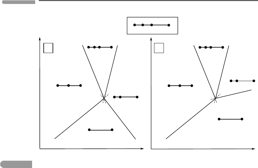
Fig. 6.8 Phase diagram for crystallization of thenardite (Na
2
SO
4
) and mirabilite (Na
2
SO
4
.10H
2
O). The slopes of the (Th), (V)
and (L) curves are unambiguous. The (Mi) curve is harder to pin down and two alternatives are shown. The correct one
is (b), see text.
conceivably be present on the Martian surface as well: thenardite (Na
2
SO
4
) and mirabilite
(Na
2
SO
4
.10H
2
O). These minerals are known to precipitate from marine brines, which
constitute a liquid phase. The process occurs at the planet’s surface, and therefore in the
presence of a gas phase. If we ignore for now the fact that the planet’s atmosphere (i.e. the gas
phase) contains various other components, we can consider this to be a binary system, and
use Na
2
SO
4
and H
2
O as the system components – we shall return to the issue of atmospheric
composition in a moment. In the binary system the four phases thenardite–mirabilite–
liquid–vapor constitute an invariant assemblage (we call a gas phase in equilibrium with a
condensed phase a “vapor”, more on this in Chapter 9). Four univariant curves radiate from
the invariant point. Using Schreinemakers’ rule and general properties about univariant
phase boundaries that we derived in Section 5.1.3, such as their Clapeyron slopes and how
r
S and
r
V determine the side of a reaction that a given assemblage is on, we can construct
the P–T phase diagrams shown in Fig. 6.8.
The orientation of the phase diagram is obtained from the (L) and (V) curves. In the first
place, both liquid and vapor are higher entropy phases than the solids, so they must be placed
on the high temperature side of these equilibria, establishing the mirror orientation of the
diagram (see Fig. 6.5). They are also higher volume (lower density) phases than the solids,
so the Clapeyron slopes of both curves must be positive. Finally, because the volume change
associated with reaction (L), in which a gas is evolved, is greater than that associated with
reaction (V), in which a liquid forms in the absence of a gas phase, equilibrium (V) must
have a steeper Clapeyron slope than (L), as shown in Fig. 6.8. There is a tacit assumption in
the last statement, which is that
r
S varies less than
r
V between reactions (L) and (V).
This is true but I have not justified it; I will return to this issue in Chapter 9 and 10.
Schreinemakers’rule determines the location of the (Th) and (Mi) curves, but their slopes
are not as easy to ascertain as those of the other two univariant curves. This is so because

307 6.2 Analysis of phase equilibrium
in both of these equilibria the liquid and gas phases appear on opposite sides of the phase
boundary, and the signs of
r
S and
r
V are not always evident. The sign of the Clapeyron
slope becomes strongly dependent on two factors: pressure and the nature and stoichiometry
of the reaction. At low pressure, such as at and near a planet’s surface, molar volumes of
gases are orders of magnitude greater than those of liquids, so that it is a safe assumption
that reactions that consume vapor and produce liquid have
r
V < 0. This is certainly
the case at the conditions at which evaporites form. Gases are much more compressible
than liquids, however, and at pressures significantly greater than that of the critical point
r
V for reactions that involve aqueous or carbonic fluids on one side and silicate melts
on the other may change sign. This becomes important when studying the formation of
magmas in the deep crust and mantle of the Earth and other planets. Staying for now with
evaporites we note that, although in general gases also have higher entropy than liquids,
the difference is not as large as that for molar volume (Chapter 9). The sign of
r
S then
becomes dependent on reaction stoichiometry, which determines the relative amounts of
vapor and liquid in a balanced reaction. The liquid along the (Th) and (Mi) curves is
an aqueous solution saturated in mirabilite and thenardite, respectively. Given the very
large H
2
O content of mirabilite, it appears reasonable to assume that, when this mineral
decomposes and liberates H
2
O, little additional H
2
O may be required to dissolve any excess
sulfate, so that the stoichiometric coefficient of the vapor is probably small. The dominant
contribution to the entropy of reaction arises from the increase in configurational entropy
that occurs when crystalline mirabilite becomes aqueous sodium sulfate. The resulting
r
S
for the (Th) reaction is positive, and hence the phase boundary has a negative Clapeyron
slope, as shown in Fig. 6.8.
Reactions such as (Mi) are in general harder to pin down, chiefly because of greater
uncertainty about the sign of
r
S . Two alternatives are shown in Fig. 6.8. A negatively
sloping reaction, case (a), requires that, with increasing temperature, thenardite reacts with
vapor to yield a saturated sodium sulfate solution. If the slope is positive, case (b), increasing
temperature causes boiling of the liquid (sodium sulfate solution) and crystallization of
thenardite. Worded like this (which I did on purpose) it appears obvious that the correct
phase diagram must be (b), and this is indeed the case for this particular system, and in
general for crystallization of evaporites from liquid H
2
O solutions. One can intuitively
justify this result by noting that thenardite is an anhydrous mineral, so that all of the H
2
O
needed to form the saturated sodium sulfate solution at the (Mi) curve must come from
condensation of vapor. In contrast to the (Th) curve, the stoichiometric coefficient of vapor
must be quite large, and the entropy contribution from the phase change of H
2
O overrides
the contribution from the breakdown of the crystalline structure of thenardite. We then have
r
S < 0, and a positive Clapeyron slope, as in Fig. 6.8b. This conclusion is, however, not
general, and in particular is incorrect for equivalent reactions in igneous systems (Worked
Example 6.3).
We now have a thermodynamically consistent phase diagram for crystallization of sodium
sulfate phases (Fig. 6.8b), but how meaningful is it in relation to natural evaporites? There
are three issues that must be addressed.
First, this is a purely schematic phase diagram. In order for it to be useful it must be made
quantitative, by calculating the actual locations of the phase boundaries in terms of the
intensive variables of interest. We have established the principles for doing so in Chapter 5,
but we have not yet discussed how to calculate equilibria involving gases at pressures other
than 1 bar (Chapter 9) nor how to calculate equilibria involving aqueous solutions (Chapter
11). We can nonetheless see the importance of Schreinemakers’ analysis. It allows us to
identify erroneous thermodynamic data, for instance if the calculated position of a phase
