Davim J.P.Machining of Hard Materials
Подождите немного. Документ загружается.

3 Mechanics of Cutting and Chip Formation 97
reduce tool wear and improve surface integrity, especially to minimize white layer
formation and induce the desired residual stress profile in the subsurface layer
[17–19]. For instance, in turning of a through-hardened AISI 4340 steel of
46 HRC hardness with coated carbide inserts, a thin pulsed jet of special cutting
fluid at velocity of 100
m/s and pressure of 20
MPa was supplied at the immediate
cutting zone at a low rate of 2
ml/h [18].
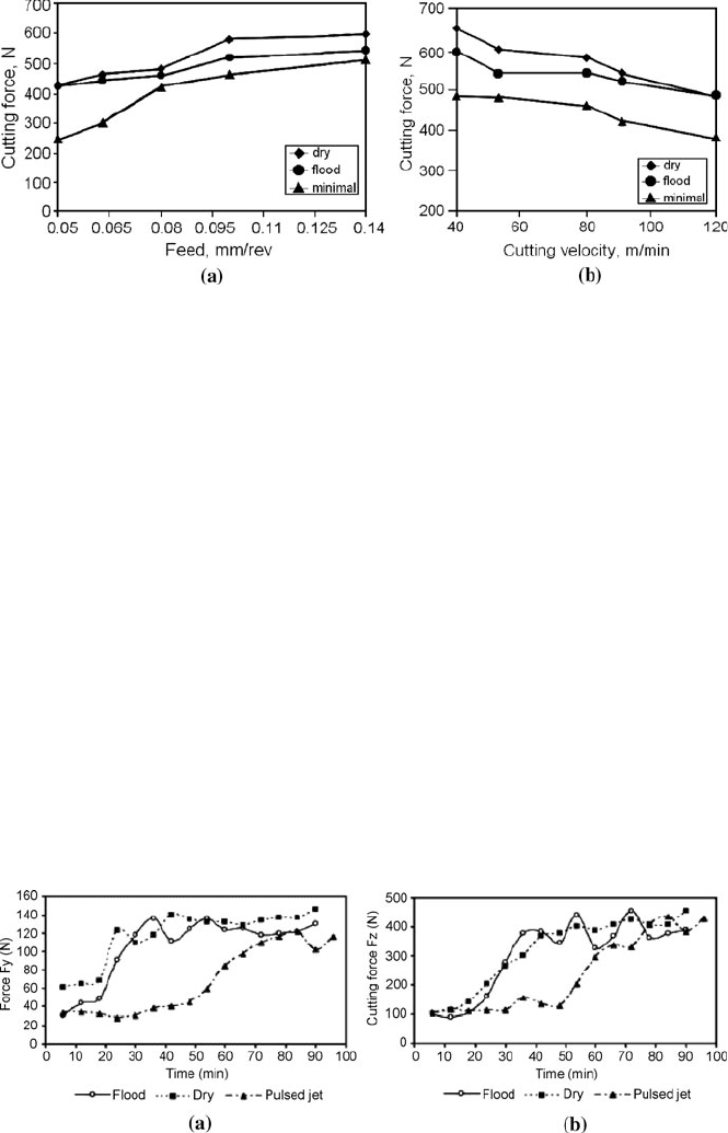
As a result, the performance of hard turning with minimal fluid application in
terms of cutting forces was changed in comparison to dry and wet conditions, as
shown in Figure 3.17. It can be easily observed that the cutting force is substan-
tially lower in a range of feed rates and cutting speeds when compared to dry turn-
ing and conventional wet turning. Presumably, minute capillaries are formed at the
tool–chip interface and they reduce the friction contribution to the cutting force.
As revealed, reduced contact length and compression chip ratio (thinner and
shorter chips were produced) are indicated of gentle frictional conditions at the
tool–chip interface.
When the milling of ASSAB F3 hardened tool steel of hardness 51 HRC with
TiAlN coated carbide ball-endmills was assisted by a special fluid injection sys-
tem, the progress of cutting force components during the process was as reflected
Figure 3.17 Cutting forces vs. feed at v
c
=
80
m/min, a
p
=
1.25
mm (a) and cutting speed a
t
f
=
0.10
mm/rev, a
p
=
1.25
mm (b) for dry, wet and MQL machining conditions [18]
Figure 3.18 Influence of cooling on the variations of cutting forces: (a) F
y
and (b) F
z
in milling
of hardened tool steel [19]
98 W. Grzesik
in Figure 3.18. Considering the whole period of cutting, it can be seen that, in
general, cutting forces in pulsed-jet mode are lower than in flood and dry milling.
However, the values of cutting forces are almost the same when tool failure crite-
rion of 0.35
mm was achieved. Similarly as for turning, due to better lubrication,
the wear curve does not express a rapid increase of flank wear at the beginning of
cutting, i.e. in the running-in period.
3.1.6 Finite-element Modelling of Mechanical Loads
As reported in many papers, for example those recently published [3, 20], which
overview the state-of-the-art of numerical modelling of hard machining, finite-
element modelling (FEM) can be extremely useful for understanding physical
phenomena and mechanisms which govern chip formation in machining of hard-
ened steel materials. In this specific problem care has to be taken to provide ap-
propriate flow-stress data and friction model, and to select the predominant
mechanism of chip formation, i.e. surface shear-cracking (SSC, originally termed
shear-crack hypothesis) or catastrophic thermoplastic instability (CTI). According
to Kountanya et al. [20], the SSC mechanism predominates in a majority of hard-
machining conditions. In the past, 2D FEM of temperature and forces was devel-
oped [21, 22] but recently 3D FEM has been applied for analysing a hard-turning
process [3, 23]. It is assumed that a hard-turning process is a typical high-speed
dynamic event with large nonlinear material deformation at high strain rates and
temperatures, complex contacts and material failure. The explicit simulation
method seems to be suitable for hard-machining processes due to small increments
(small feed and depth of cut).
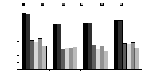
Figure 3.19 shows the comparison of measured and simulated cutting forces
for four different micro-geometries of PCBN inserts keeping v
c
=
300
m/min,
f
=
0.15
mm/rev and a
p
=
1
mm. It is clear that the FEM procedure using the John-
0
100
200
300
400
500
600
700
800
Chamfer Hone 40 Var Hone 50 WF 30:60
Force, N
Fc-exp Fc-FEA Ft-exp Ft-FEA Fz-exp Fz-FEA
Figure 3.19 Comparison of measured and simulated forces for different micro-geometry o
f
PCBN tools [3]
3 Mechanics of Cutting and Chip Formation 99
son–Cook (JC) material constitutive model, applied by Özel [4], which adopts
pressure-dependent shear friction, gives acceptable agreement between experiment
and simulation. Similarly, in the FEM simulations with the coupled flow-stress
model performed by Kountanaya et al. [20], the maximum errors in predicting
cutting F
C
and thrust F
T
forces were 20
% and 9
%. Chen et al. [24] have estab-
lished that the resultant cutting force for hone edges is lower but such tools can be
employed for hard turning when the tensile principal stresses (TPS) acting on the
tool can be reduced to a low magnitude. On the other hand, chamfer edges are
more robust because their use allows the TPS to be reduced by about 25
% [25],
which significantly reduces the probability of catastrophic failure.
Huang and Liang [26] have modified the JC model by considering Oxley’s ma-
chining predictive theory, in particular to represent the workpiece material prop-
erty as a function of strain, strain rate and temperature. This model was validated
experimentally for AISI H13 tool steel of 52 HRC hardness and both low-CBN-
content and high-CBN-content tools.
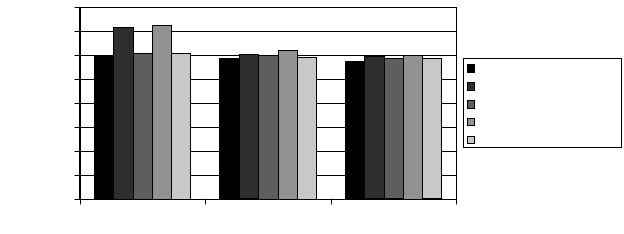
The effect of different CBN content tools and variable cutting speed on pre-
dicted values of cutting force in turning of AISI H13 tool steel (52 HRC) is pre-
sented in Figure 3.20. It is observed that both the cutting (tangential) and thrust
forces are higher when generated by the high-CBN-content tools. As discussed,
the differences in force prediction can result from variation in material hardness
and the effective rake angle assumed.
3.2 Chip Formation in Hard Machining
3.2.1 Criteria for Crack Initiation and Propagation
One of the characteristic phenomena occurring in the machining of hardened steels
with geometrically defined cutting tools is the formation of saw-tooth chips.
Catastrophic failure causing saw-tooth chip formation in the primary shear zone is
0
200
400
600
800
1000
1200
1400
1600
75 150 200
Force, N
Pred (low CBN)
Exp (low CBN)
Pred (high CBN)
Exp (high CBN)
Pred (Oxday’s approach)
Figure 3.20 Comparison of predicted and measured values of cutting force for different CBN-
content tools and variable cutting speed [26]
100 W. Grzesik
usually attributed to either cyclic crack initiation and propagation or to the occur-
rence of a thermoplastic instability [27, 28]. Section 3.1.6 described these mecha-
nisms as SSC and CTI [20]. The periodic crack theory assumes that periodic shear
cracks first develop near the surface of the work and proceed downward along the
shear plane toward the tool tip. Following crack formation, bands of concentrated
shear may or may not then develop [29].
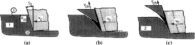
Figure 3.21 shows the cyclic mechanism of the formation of chip segments
due to crack initiation (numbered successively 1 and 2 close to the machined
surface) when the UCT is higher than 0.02
mm. This is because continuous chips
are formed for very small UCT less than h
<
0.02
mm.
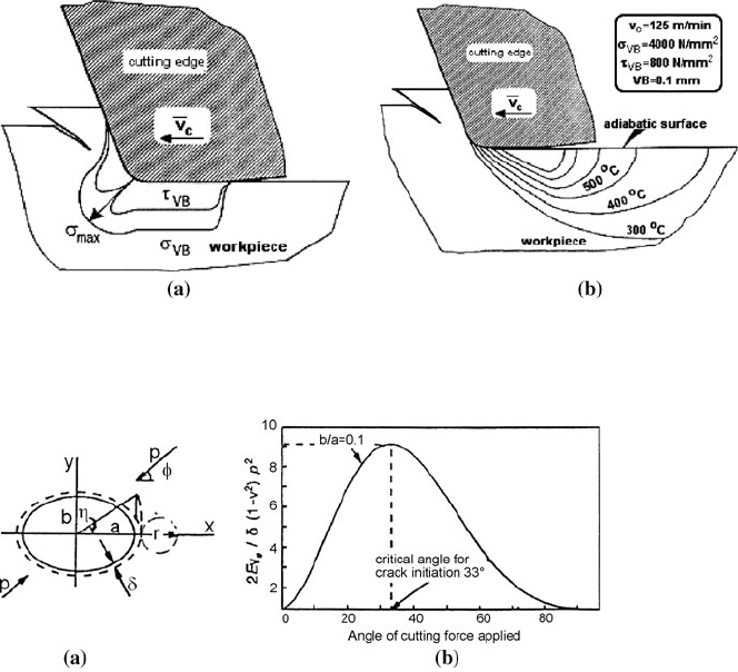
Associated stress and temperature fields developing in the vicinity of the cut-
ting edge are shown in Figure 3.21. It can be seen in Figure 3.21 that in machining
of hardened 100Cr6 bearing steel, the direct normal stresses
σ
VB
of the magnitude
of approximately 4000 MPa result in high mechanical and thermal stresses ex-
tended to the machined surface of the workpiece. Thermal stresses originate
mainly in the intensive friction between flank wear land and the workpiece, which
for the friction coefficient of 0.2–0.3 causes high tangential stress [31]. The tem-
perature field in the workpiece due to friction, predicted by assuming a semi-
infinite moving body with an adiabatic surface and the heat partition to the work-
piece of 80
%, is as shown in Figure 3.21 (b).
In cases for which the chip speed is high enough, the temperature near the
machined surface may reach the
γ
–
α
transition temperature, martensite produced
by friction development can form the so-called white layer observed in chip
micrographs.
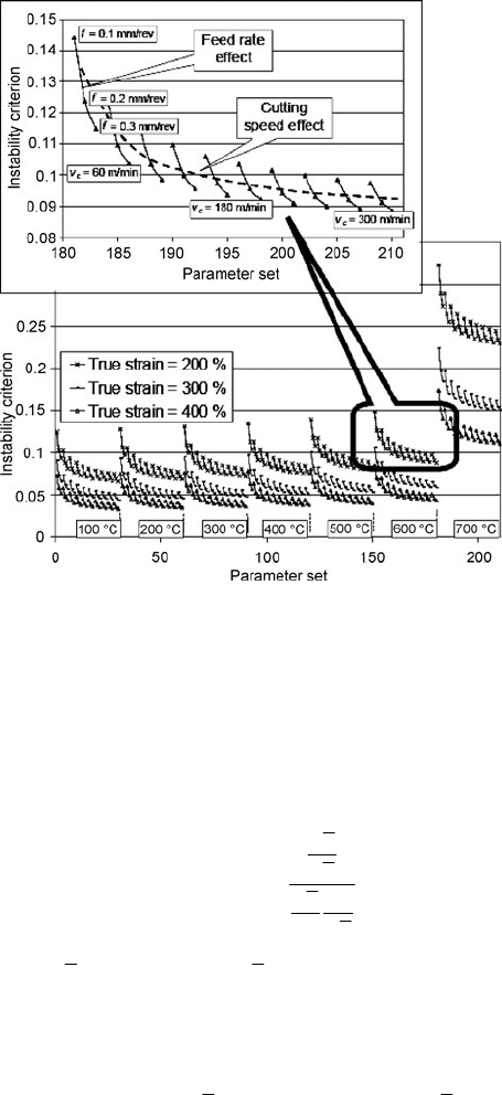
Elbestawi et al. [17] developed the chip formation model, in which it starts with
initiation of a crack at the free surface of the workpiece, by considering the direc-
tion of crack initiation using the surface layer energy/strain energy density crite-
rion. It is assumed that the machined surface is rough and notched, and it locally
has very small elliptical notches, as shown in Figure 3.22 (a). The compressive
cutting pressure p acts at a certain angle
Φ
from the major axis of the elliptical
notch. According to this hypothesis, the crack at the free surface will initiate at a
critical angle
Φ
cr
when surface layer energy reaches its maximum value at the
minimum applied pressure (Figure 3.23 (b)). For AISI 1550 case-hardened steel
(60 HRC) machined with mixed ceramic tools at v
c
=
66–120
m/min, f
=
0.025–
Figure 3.21 Chip formation mechanisms for hardened 100Cr6 (60–62 HRC) steel and UCT o
f
0.05
mm (when h
>
0.02
mm) when using PCBN tool: (a) first stage, (b) intermediate stage, an
d
(c) second stage [30]
3 Mechanics of Cutting and Chip Formation 101
0.2
mm/rev and a
p
=
0.5–2
mm, the maximum surface energy was obtained for the
crack initiation angle equal to 33°. For this case of hard machining, the relevant
angle of crack propagation was found to be equal to about
Θ
=
55°. The value of
the fracture angle higher than 45° suggests that in hard turning the chip formation
mechanism differs from the pure shear deformation process only.
3.2.2 Criteria for Shear Instability
According to the adiabatic shear theory [1], the root cause of saw-tooth (segmen-
tal) chip formation is a CTI for which the decrease in flow stress due to thermal
softening exceeds the associated strain hardening. Materials sensitive to the forma-
tion of localized shear chips have either poor thermal properties (titanium alloys,
nickel-based superalloys) or limited ductility, such as hardened alloy steels.
Figure 3.22 Associated distributions of mechanical stresses (a) and temperature (b) before
crack propagation for machining 100Cr6 (63 HRC) steel. Cutting conditions: cutting speed o
f
125 m/min and tool wear VB
=
0.1
mm) [31]
Figure 3.23 Unit elliptical notch under compression (a) and variation of maximum surface
layer energy with loading angle
Φ
[17]
102 W. Grzesik
Figure 3.24 Shear instability criterion for hardened 100Cr6 steel [22]
The first criterion for shear instability was formulated by Recht (see Chapter 7
in [1] or Trans. ASME, J. Appl. Mech., Vol. 31, 1964, 189–193). It assumes that
the slope of the strain-hardening curve becomes negative when an increase in
shear strain is associated with a decrease in shear stress [22]. This means that
shear localization occurs when values of the criterion R given by Equation 3.2 will
be between 0 and 1. If this ratio is equal to 1, a catastrophic slip will dominate.
,and 0 1RR
dT
Td
τ
γ
τ
γ
∂
∂
=≤≤
∂
∂
(3.1)
where
τ
is shear stress and
γ
is shear strain.
Another criterion, proposed by Semiatin and Rao, uses the strain-rate-
dependent
β
parameter, for which shear localization predominates when it is
greater than 5 [22].
Figure 3.24 shows the template of instability criterion for the 210-parameter
set
c
(10 7 3 3 )×××vTf
γ
when T
=
100–700
°C, 25,=−
γ
v
c
=
30–300
m/min and
f
=
0.1–0.3
mm/rev. The shear strain was determined based on standard hot com-
pression tests for temperature varying from 20 to 700
°C (relevant true stress–true
strain curves are presented in the lower diagram in Figure 3.24). It should be noted
3 Mechanics of Cutting and Chip Formation 103
that for the material and cutting conditions used, the value of R criterion is always
between 0 and 1 but is not higher than 0.15. Moreover, the increases in all vari-
ables (cutting speed and feed rate) result in the decrease of R value.
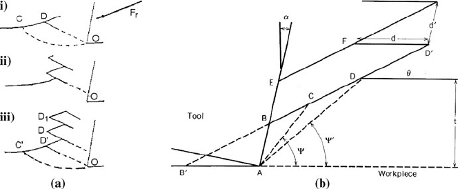
3.2.3 Mechanisms of Chip Formation
The nature of chip formation in hard machining is quite different than in more con-
ventional machining. After reviewing the mechanics of this unique type of chip
formation some mechanisms which govern it will be explained and discussed. The
first, simple periodic-cracking based model for producing saw-tooth chips shown in
Figure 3.25 (a), was proposed by Shaw [29]. At point C (case (i)) material in the
free surface begins to rise and assumes a direction CD parallel to the resultant cut-
ting force F
r
. A shear crack initiates at point D and develops downard along shear
plane DO toward the rake face (case (ii)). When the tool moves, the chip slides
along the cracked surface until the next crack forms at point D′ (case (iii)). Initially
the crack, called a gross crack (GC), will be continuous across the width of the chip
for sufficiently brittle materials, but for less brittle materials at higher cutting
speeds, it may become discontinuous as the crack proceeds towards the tool tip.
Such disconnected localized cracks will be termed microcracks (MC). The distance
between one segment that slides relative to its neighbour during one cycle depends
upon the distance p (C′D′) between cracks on the machined surface. When the chip
pitch p
c
(Figure 3.28) is higher than p (chip compression ratio k
h
<
1 and shear angle
greater than 45°), this is a result of the compressive stresses on the material in the
MC zone. The thinning of the MC region is usually the case when hard steel is
turned with a negative rake tool. On the other hand, material in the GC region is
carried along with the MC material, resulting in k
h
for the entire chip being greater
than one. There are then two regions as the chip proceeds up the tool face – the ma-
terial between GCs sliding outward and deformation in the MC region resulting in
bending downward and running along the tool face, the concentrated shear bands.
Based on experimental observation, Shaw and Vyas [29] reported that in
face milling of case carburized AISI 8620 steel (61 HRC) with PCBN tools at
v
c
=
150
m/min, f
=
0.13 and 0.25
mm/rev and a
p
=
0.13 and 0.25
mm the chip for-
mation is of a cyclic saw-tooth type.
In another mechanical model of chip segmentation, segmented chips are pro-
duced by catastrophic strain localization occurring above some critical cutting
speed. As shown in Figure 3.25 (b), catastrophic shear is initiated along the line
B′D′ (inclined at an angle
Θ
relative to the workpiece surface) when the tool tip is
at point B′. As the tool moves from B′ to A, the stress required for further defor-
mation along BD decreases due to the thermal softening and the tool experiences
rapid unloading along BE. At the same time, the loads increase along AB as the
material in triangular region B′AB is indented and sheared.
Because the shear zone is nearly adiabatic and the workpiece temperature
ahead remains essentially at ambient, the formation of the next segment is deter-
mined highly by the stresses applied to the workpiece along AB. In this model the
104 W. Grzesik
segment spacing is a linear function of the UCT but increases asymptotically with
cutting speed, depth of cut and rake angle. For instance, for the orthogonal ma-
chining of a through-hardened AISI 52100 bearing steel of 50–65 HRC with
PCBN tools, the onset of chip segmentation due to adiabatic shear was observed at
relatively low cutting speeds (below 1
m/s) [16]. In addition, these shear bands are
formed at frequencies in the range of 50–120
kHz when cutting speed was varying
from 0.35 to 4.3
m/s and segment spacing becomes more periodic as cutting speed
is increased. It is also noted that the dynamics of chip segmentation caused by
thermal and elastic interaction between one and next shear zones can lead to ape-
riodic variations in the segment spacing [28].
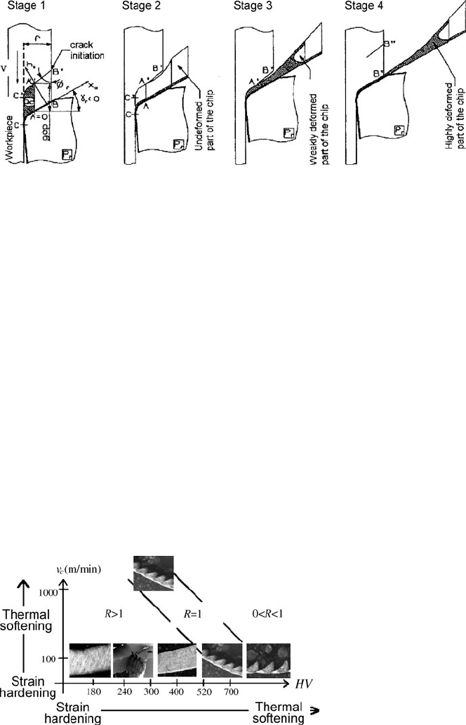
Producing saw-tooth chips in orthogonal cutting of the 100Cr6 steel of
HV730
hardness at cutting speeds of 25–285
m/min and feed rates of 0.0125–
0.2
mm/rev was confirmed by Poulachon et al. [22]. Relevant mechanisms of
formation of such chips, identified by means of a chip frozen technique (using a
quick-stop device) are illustrated in Figure 3.26. According to Figure 3.26, four
subsequent stages can be distinguished, namely:
1. During the tool indentation compressive stresses are induced in a zone around
the cutting edge. Simultaneously, a crack at the workpiece surface at the angle
Φ
f
is initiated and it is followed by a shear plane which extends toward the cut-
ting edge.
2. The chip volume of AA′BB′ localized between the crack and the tool chamfer is
ejected without deformation. The gap AA′ decreases progressively with the tool
movement and the chip thickness h
c
decreases. The temperature can increase up
to the martensite transformation A
3
and a white layer may be produced.
3. The gap AA′ becomes so narrow that the material ejection velocity is very high
and plastic deformation of the chip is very intensive. The second part of the
chip of very small thickness is formed with extremely fast cooling.
4. The chip segment is formed and the gap AA′ fully disappears. The compressive
stresses at the free surface are again high enough to produce a new crack. This
periodic phenomenon will repeat itself leading to cyclic chip formation.
Figure 3.25 Mechanism of saw-tooth chip formation after Shaw [29] (a), and simple model o
f
segment formation after Davies et al. [16] (b)
3 Mechanics of Cutting and Chip Formation 105
Figure 3.26 Stages of saw-tooth chip formation [21, 22]
3.2.4 Chip Morphology in Typical Machining Operations
It is well known that in machining processes chip morphology changes depending
on the chip formation mechanisms (strain hardening versus thermal softening) but
as discussed in Section 3.2.3 in hard machining saw-tooth type chips with differ-
ent shapes and dimensions are prominently produced. In this section, the influence
of cutting conditions and workpiece hardness on chip morphology will be ad-
dressed to hard-turning and milling operations. Special focus will be given to
variable factors favouring saw-tooth chip formation.
Figure 3.27 depicts that depending on the workpiece hardness three characteris-
tic values of the R criterion (Equation 3.2) can be determined and all possible chip
morphologies are formed with the hardness ranging from 180 to 700 HV. In particu-
lar, the separating point of about 400 HV divides all chips produced into continuous
shear-type chips (R
>
1) and saw-tooth chips formed by cracking (0
<
R
< 1).
Figure 3.28 shows the longitudinal sections of chip produced for differently
hardened AISI 4340 steel with CBN tools. It was validated that chips produced for
the work material of lower hardness are continuous and the main formation
Figure 3.27 Variation of chip morphology with hardness [23]. Cutting parameters: v
c
=
100
m/min, f
=
0.1
mm/rev, a
p
=
1
mm
106 W. Grzesik
mechanism is plastic deformation. However, when the hardness exceeds 45 HRC,
the produced chips are thinner and their shapes change to saw-tooth type. As ex-
perimentally confirmed, the reduction of chip thickness results from the increase
of the shear angle (
Φ
≅
20° for 35 HRC and
Φ
≅
40° for 60 HRC). Because heat is
mostly transported into the chip, more heat is concentrated on the local shear
bands, and a saw-tooth chips are formed.
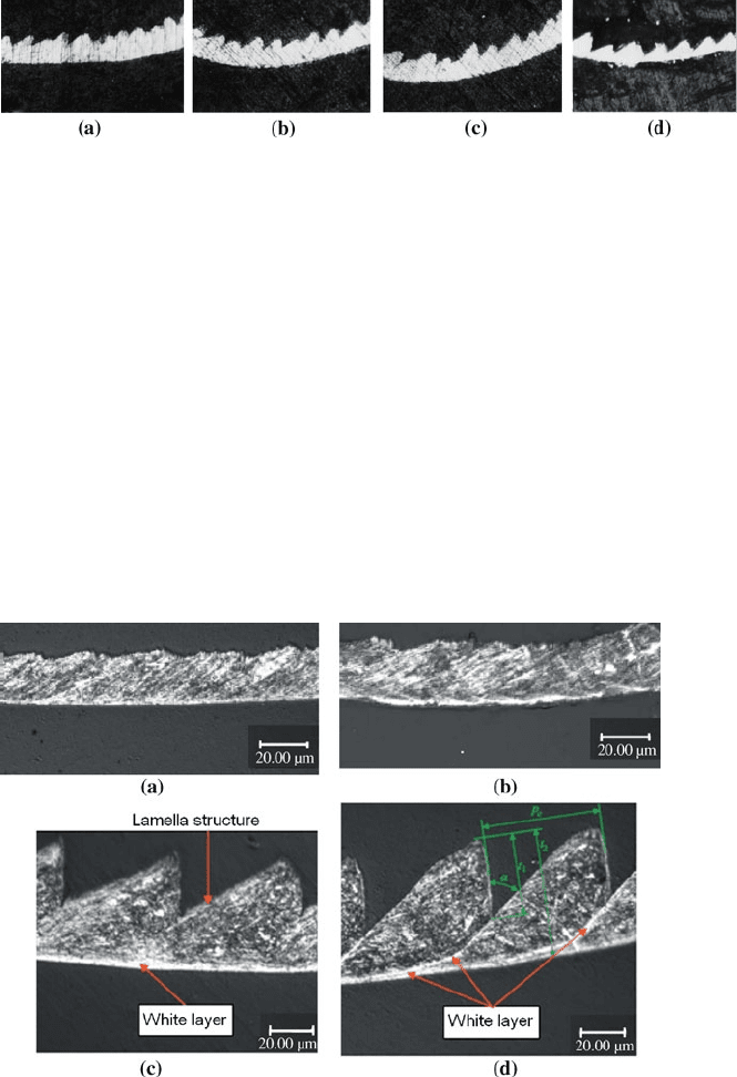
Figure 3.29 shows the cross-sectional images of the chip top surface obtained
in the milling of AISI H13 tool steel (50
±
HRC) with milling cutters equipped
with (Ti, Al)N-TiN-coated carbide inserts. Two different types of chips are pro-
duced when keeping the following cutting parameters: v
c
=
100–250
m/min,
f
z
=
0.05–0.20
mm/tooth, a
e
=
0.3–0.6
mm, a
p
=
1.0–2.5
mm; the near-uniform de-
formed continuous chips and the saw-tooth chips at higher cutting speeds and
feeds. It can be concluded based on these observations that the chip morphology
Figure 3.28 Types of the saw-tooth chips produced in turning of AISI 4340 steel of different
hardness: (a) 45 HRC, (b) 50 HRC, (c) 55 HRC, and (d) 60 HRC [32]
Figure 3.29 Combined effect of cutting speed and feed on cross-Section of chip top surfaces (p
c
:
segment pitch, t
1
: saw height, t
2
: chip thickness) [33]: (a) v
c
=
100
m/min, a
p
=
2
mm, a
e
=
0.6
mm,
f
z
=
0.05
mm/tooth, (b) v
c
=
150
m/min, a
p
=
2.5
mm, a
e
=
0.4
mm, f
z
=
0.10
mm/tooth, (c) v
c
=
200
m/min, a
p
=
2
mm, a
e
=
0.4
mm, f
z
=
0.15
mm/tooth, and (d) v
c
=
250
m/min, a
p
=
2.5
mm,
a
e
=
0.6
mm, f
z
=
0.20
mm/tooth