Davim J.P.Machining of Hard Materials
Подождите немного. Документ загружается.

87
Chapter 3
Mechanics of Cutting and Chip Formation
W. Grzesik
This chapter presents the basic knowledge on mechanics of the machining
process
in which the workpiece material hardened to 45–70 HRC hardness is machined
with mixed ceramic or cubic boron nitride tools. Specific cutting characteristics,
including cutting forces and cutting energy, and chip formation mechanisms are
discussed in terms of process conditions. Additionally, currently developments
in finite-element modelling are overviewed and some representative results are
provided.
3.1 Mechanics of Hard Machining
3.1.1 Cutting Tools for Hard Machining
Hard machining is commonly defined as the process in which part pieces with
hardness values over 45 HRC, but more typically in the 58–68 HRC range, are cut
using specially prepared tools with geometrically defined cutting edges [1, 2]. The
cutting-tool materials used are typically polycrystalline cubic boron nitride
(PCBN), mixed (Al
2
O
3
-TiC) ceramics and sometimes cermets. The tooling choice
will need to be matched to the application, desired production rates and the operat-
ing-cost goals. However, CBN is the most dominant choice for the more demand-
ing applications of size and finish and particularly those components which have
been transitioned from grinding. It is well known that in such extreme applications
better tool performance can be achieved by using geometries with negative rake
_
_________________________________
W. Grzesik
Department of Manufacturing Engineering and Production Automation,
Opole University of Technology, P.O. Box 321, 45-271 Opole, Poland
e-mail: w.grzesik@po.opole.pl
88 W. Grzesik
angles but cutting-edge configuration and its preparation also play a dominant role
in a machining success.
In general, the cutting-edge geometry is critical in hard machining because
tools with superior edge strength are required to withstand the large tool stresses
produced. As a result, tool cutting edges which are designed to cut hardened steels
are often equipped with a chamfer (sometimes double chamfer) between the rake
and clearance faces, termed by ISO the T-land and K-land respectively. The cham-
fer angle of –20° and the chamfer width of 0.1 (0.2) mm are typically selected. In
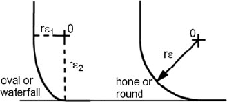
order to protect the cutting edges from microchipping, additional hones are made
as shown in Figure 3.1.
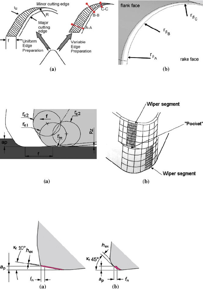
Because uniform edge micro-geometry along the corner radius causes exces-
sive ploughing at the minor cutting edge (a very low edge radius to uncut chip
thickness as shown in Figure 3.2 (a)) the PCBN tools with variable honed cutting
edges are implemented [3, 4]. As can be seen in the CAD model of variable
shaped cutting edge, the edge radius at points A, B and C decreases uniformly
from the major to minor cutting edges, i.e. r
ß A
>
r
ß B
>
r
ß C
. This causes a constant
uncut chip thickness to edge radius ratio to be maintained along the active part of
the corner.
Recently, wiper inserts, which combine the high feed capability and high-
quality surface finish produced by large round inserts, have gained popularity in
hard-machining applications. As shown in Figure 3.3 (a), multi-radii tool corner
contains a small smoothing part of the radius of r
bo
which is parallel to the feed
direction. Additionally, Figure 3.3 (b) shows a more universal design of a wiper
corner with both left- and right-handed wiper segments. By the application of such
a solid wiper insert (the Crossbill™ by Seco Tools [6]), it is possible to machine a
perfect radius with no deviation from a normal radius along with axial turning,
which utilizes the full wiper effect.
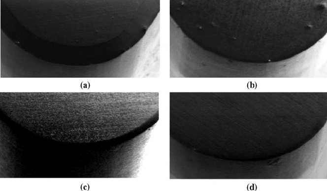
Figure 3.4 shows a unique new design of solid CBN inserts with a straight part
of the cutting edge blending into a wiper. As a result, the smaller approach angle
κ
r
reduces the depth of cut and provides constant chip thickness, so higher feed
rates up to 0.4
mm/rev can be applied. Figure 3.5 illustrates the micro-geometry of
a few of the inserts at a magnification of 50 times obtained by using field emission
scanning electron microscopy.
Figure 3.1 Profiles of honed cutting
edges for hard-machining applications [3]
3 Mechanics of Cutting and Chip Formation 89
Figure 3.2 Comparison between uniform and variable micro-geometry of the corner (a) and
CAD model of the variable-hone edge design (b) [3, 4]
Figure 3.3 CBN wiper inserts [5, 6]: (a) one-handed design (f: feed; a
p
: depth of cut; r
ε1
and r
ε2
:
radii of wiper curvature; r
bo
: radius of smoothing part; R
z
: valley-to-peak height), and (b) two-
handed design
Figure 3.4 Xcel geometry and comparison of chip thicknesses for modified wiper (a) and
conventional corner (b) [6]
90 W. Grzesik
Figure 3.5 PCBN inserts with different micro-geometries of cutting edges: (a) chamfer insert
(20°
×
0.1
mm), (b) uniform hone (r
β
=
50
μm), (c) waterfall-hone insert (r
β
1
=
30
μm, r
β
2
=
60
μm),
and (d) variable-hone insert (r
β
A
=
50
μm, r
β
B
=
10
μm) [4]
3.1.2 Mechanical Models of Hard Machining
Hard machining is a specific process performed under unique technological and
thermo-mechanical conditions and, as expected, the cutting-process mechanisms
(chip formation, heat generation, tool wear) differ substantially from those ob-
served in machining soft materials. As described in [1, 7, 8], hard machining is
performed also as a dry high-speed machining process. In particular, while small
depths of cut (0.05–0.3
mm) and feed rates (0.05–0.2
mm/rev) are used, both small
undeformed chip thickness (UCT) and the ratio of the UCT to the radius of the
cutting edge are obtained in such processes. These geometrical relationships lead
to an effective rake angle of –60 to –80° and, as a result, extremely high pressure
is generated to remove material in the vicinity of the cutting edge. Moreover,
a large corner radius causes the components of the resultant cutting force to in-
crease, along with extremely high thermal stresses.
The principal model of the orthogonal cutting process with a chamfered tool
proposed by Ren and Altintas [9] is shown in Figure 3.6. It should be primarily
noted that this model incorporates a small dead metal zone OBH created by the
chamfer in contrast to the obviously known models with both primary and
secondary plastic deformation zones. As a result, the plastic flow under the
chamfer edge follows in the direction opposite to the tool motion in order to
avoid the negative energy dissipation in the cutting zone. The proposed model
utilizing appropriate slip-line solution is able to generate the optimal chamfer
angle and cutting speed (so it will be useful in modelling of high-speed machin-
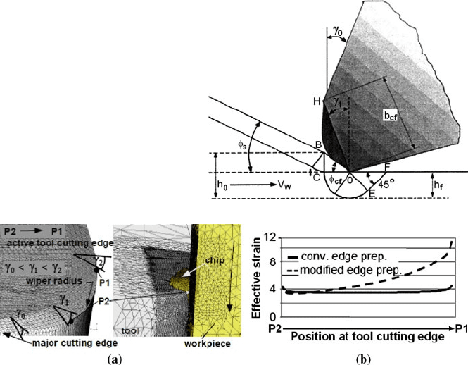
3 Mechanics of Cutting and Chip Formation 91
ing of hardened materials) and guarantee lowest tool wear and relatively low
cutting forces.
As reported in Section 3.1.1, cutting edges of PCBN tools for hard turning typi-
cally have a constant value of the negative rake angle on the major first face. In
the case shown in Figure 3.7 (a), wiper inserts were prepared in such a way that
the inter-linked tool edge combines micro-parts of round and rhombic tool inserts
and provides variable chamfer width and continuous variation of the chamfer
angle up to
γ
2
=
–60° [10]. In consequence, the local chip thickness approaches
zero at the position of the wiper radius, where the peripheral land corresponds to
the bluntest chamfer. Moreover, as shown in Figure 3.7 (b), the effective plastic
strain increases within points P1 and P2, and, as a result, the cutting-edge blunt-
ness is correlated with the degree of plastic deformation of the machined surface.
3.1.3 Cutting Forces
Specific cutting conditions of the hard-machining process and complex micro-
geometrical features of cutting tools used should result in different behaviour of the
process including process mechanics. It suggests that values of force components
Figure 3.6 Model of orthogonal
machining with chamfered edge
tools [9]
Figure 3.7 Wiper insert with local variable rake angles (a) and distribution of effective strain (b)
[10]
92 W. Grzesik
and relationships between them should differ from those obtained in machining of
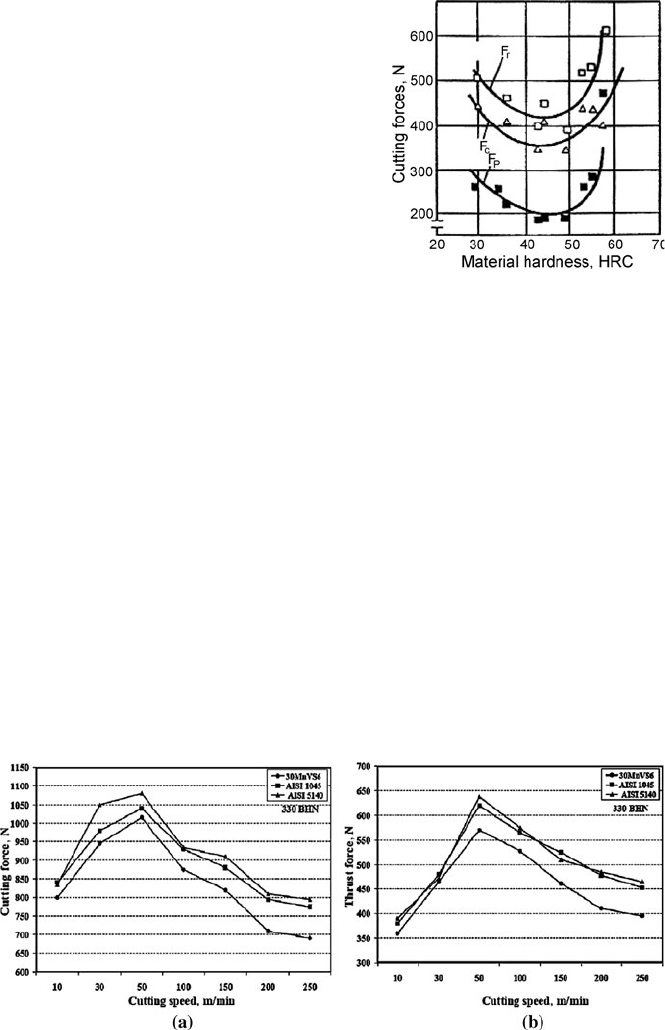
soft materials. First, it can be observed in Figure 3.8 that cutting forces increase
drastically when machining materials with hardness higher than about 45 HRC
(this value is often referenced as a lower limit of hard-part machining).
In particular, larger negative rake angle and tool corner radius influencing the
passive force F
p
increases remarkably and this effect means that an absolutely stable
and rigid process has to be provided. This requirement has to be especially kept when
using super-hard tools with multi-radii smoothing geometry (so-called wiper tools).
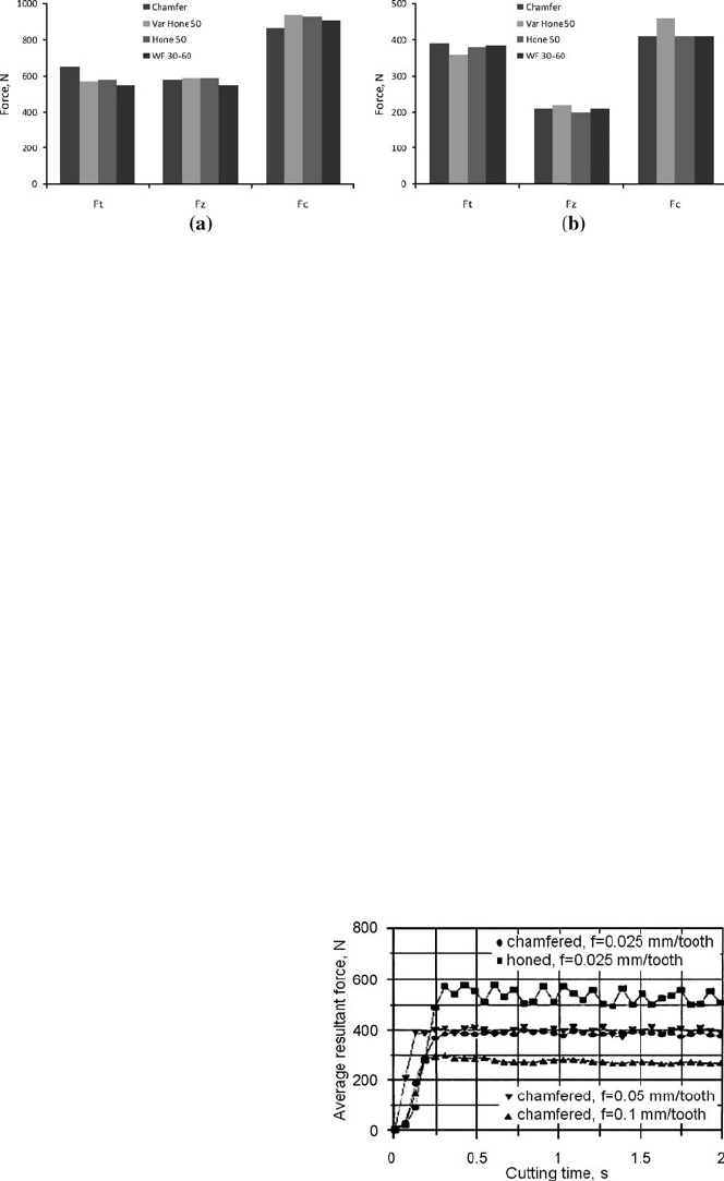
It is shown in Figure 3.9 that for micro-alloyed 30MnVS6 and quenched–
tempered (Q-T) AISI 1045 and AISI 5140 steels, all hardened to about 300 HBN,
the cutting and trust force variations with an increase of cutting speed from
10–250
m/min revealed characteristic peaks at the cutting speed of about 50
m/min
[11] independent of steel grades. It should also be noted that the effect of thermal
treatment (Q-T) is more pronounced than micro-alloying at the same cutting con-
ditions. Similar curvature was obtained for the force-feed function. According to
the experimental data provided, the cutting speed of about 200
m/min seems to be
optimal for appropriate machining operations.
Figure 3.8 Influence of steel hardness on
cutting forces (v
c
= 90
m/min, f
=
0.15
mm/rev,
a
p
= 0.9
mm) [2]
Figure 3.9 Influence of cutting speed on cutting (a) and thrust (b) forces for three hardened
steels of 300
BHN using TiN-coated carbide tools, f
=
0.11
mm/rev [11]
3 Mechanics of Cutting and Chip Formation 93
Figure 3.10 Measured cutting forces in turning of hardened AISI 4340 steel: (a) v
c
=
125
m/min,
f
=
0.15
mm/rev, a
p
=
1
mm, and (b) v
c
=
175
m/min, f
=
0.15
mm/rev, a
p
=
0.5
mm [3]
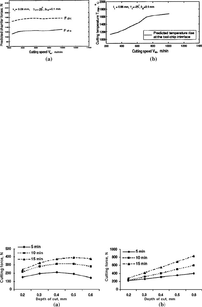
The average values of measured components of the resultant cutting force for
different edge micro-geometry shown in Figures 3.1 and 3.2 and two cutting
speeds of 125 and 175
m/min are presented in Figure 3.10. For the cutting speed of
v
c
=
125
m/min, waterfall hone edge with 30:60-μm edge radii yielded the lowest
radial force (F
t
) followed by variable-hone 50-μm edge radius. On the other hand,
the latter design produced the highest cutting force (F
c
). Similarly, at the higher
tested cutting speed of 175
m/min (Figure 3.10 (b)), PCBN tools with variable-
hone cutting edges (VarHone50) produce higher cutting forces but measured ra-
dial forces decrease in comparison to other cutting-edge geometries. In addition, it
is revealed [10] that for modified wiper geometry (Figure 3.7 (a)) the angle be-
tween the resultant cutting force and the resultant passive force is significantly
reduced when the chamfer angle varies from
γ
1
=
–10° to
γ
2
=
–60°.
As presented in Figure 3.11, the cutting-edge preparation has a significant effect
on the cutting forces generated in high-speed milling of H13 tool steel, heat treated
to hardness of 55 HRC, using ball-nose endmills with brazed CBN inserts. In this
case, the highest values of the resultant cutting force (F
r
) were obtained for honed
edges for which the large negative effective rake angle results in the intensification
of the ploughing effect, which visibly increases the friction force component. On
the other hand, the lowest cutting force was recorded for chamfered cutting edges
when using higher feed rates of 0.1
mm/tooth. This is because increasing the feed
for chamfered cutting edges results in a more stable cutting process.
Figure 3.11 Effect of feed and
edge preparation on cutting forces
in milling of hardened AISI H13
tool steel [12]
94 W. Grzesik
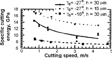
Figure 3.12 Influence of cutting speed on chamfer forces and interface temperature [9]
Figure 3.12 illustrates how cutting speed influences both the chamfer force (F
cf-t
and F
cf-c
in the feed and cutting directions, respectively) and corresponding cutting
temperature when using CBN chamfered tools with 0.1-mm chamfer width and
–25° chamfer angle. In this study, three cutting speeds of 240, 600 and 1000
m/min
were selected. As can be seen in Figure 3.12 (a), the chamfer forces seem to be in-
dependent of cutting speed rise because the temperature rise in the primary defor-
mation zone is rather small, not exceeding 50
°C. On the other hand, the temperature
in the chip–rake-face contact zone rises significantly up to above 1500
°C at cutting
speed of 600
m/min. A practical recommendation is that CBN tools can operate
effectively up to 600
m/min because they do not exhibit significant crater (diffu-
sive) wear and micro-cracks.
For the given material couple
Al
2
O
3
/TiC–AISI D2 of about 60 HRC, the de-
pendence of the cutting force on depth of cut for conventional and wiper insert
configurations and three machining times (5, 10 and 15
min) are shown in Fig-
ure 3.13. In particular, the cutting forces recorded for wiper tools (Figure 3.13b)
change almost linearly but for conventional tools the F
c
–a
p
functions have visible
maximum points at depths of cut in the vicinity of a
p
=
0.45
mm. Probably, in the
latter case tool wear causes the geometry of the cutting edge to become less nega-
tive, in contrast to wiper tools for which tool wear is substantially lower [14] (for
wiper tools the increase of cross-sectional area of cut is the predominant effect).
Figure 3.13 Influence of depth of cut on cutting force for f
=
0.1
mm/rev, v
c
=
80
m/min for
conventional (a) and wiper (b) inserts in machining of AISI D2 cold-work tool steel with Al
2
O
3
-
TiC ceramic (CC650
grade) tools [13]
3 Mechanics of Cutting and Chip Formation 95
Arsecularatne et al. [15] have investigated variations of cutting (F
c
), feed (F
f
)
and radial (F
r
) forces with a machining time of a few minutes in turning hardened
AISI D2 steel of 62 HRC with PCBN tools. The most feasible feeds and speeds
fell in the ranges of 0.08–0.20
mm/rev (0.14
mm/rev for finishing and 0.2
mm/rev
for roughing operations) and 70–120
m/min, respectively. It was found experimen-
tally that the cutting force shows a little increase with machining time and F
c
is the
largest force, while F
f
is the smallest force. Generation of a larger F
r
than F
f
is
common in hard turning.
3.1.4 Cutting Energy
The specific cutting energy (SCE) is one of important process indicators which
quantify the level of energy consumption and influence the industrial applications
of a given machining operation. Figure 3.14 shows the SCE for orthogonal turning
of AISI 52100 bearing steel (60 HRC) using a low-CBN-content (70
%) tool for
various tool and cutting geometries, i.e. for variable rake angle and UCT. Accord-
ing to the data presented in Figure 3.14, the SCE for this hard-machining operation
ranges from 6 to 11
GPa, which is substantially higher than for machining conven-
tional, softer steels. Not surprisingly the highest SCE was obtained for tools with
very large negative rake angle (
γ
0
=
–27°) and small UCT of 15.4
μm. Moreover,
the SCE decreases with cutting speed rise but predominantly for tools with higher
negative rake angles.
According to the common practice of hard machining, the high SCE required to
machine hardened steels lowers the critical depth (or width) of cut for which re-
generative chatter occurs. Thus, to maintain high stability at reasonable metal-
cutting rates, the stiffness and damping of the machine-tool system must corre-
spondingly be high.
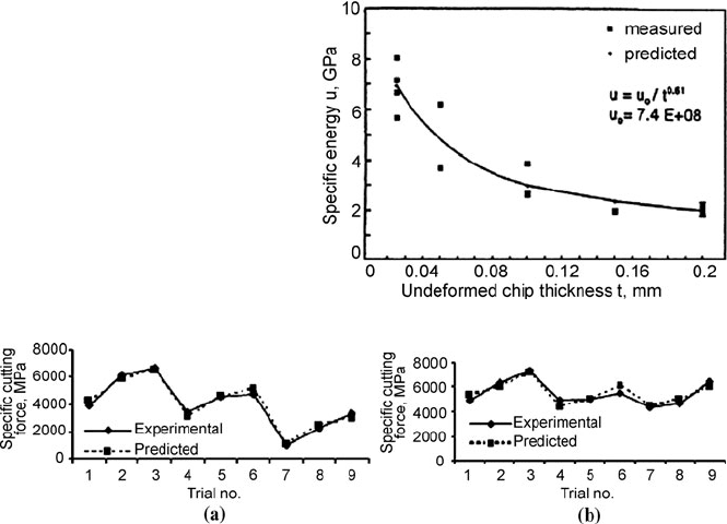
At very low feeds, the UCT is considerably less than the radius at the tool tip
and the effective rake angle becomes largely negative. The material ahead of the
rake face is in an intensely compressive stress state. In such a case, a large volume
of material becomes fully plastic before a very thin chip is formed. This causes an
exponential increase in specific energy with smaller UCT values, as shown in
Figure 3.15. By analogy, hard turning seems to be similar to the grinding process.
Figure 3.14 SCE vs. cutting speed
for orthogonal turning of hardened
bearing steel [16]
96 W. Grzesik
However, the main difference (see Section 3.2.1) is that fracture is the root cause
of chip formation in hard machining.
Figure 3.16 shows how specific cutting force (energy) changes for different
CC650 ceramic-insert configurations (conventional, wiper general and wiper hard-
part turning) when machining high-chromium AISI D2 cold-work steel of average
hardness 59/61 HRC. In this investigation the trial time was varied from 5–15
min
and the depth of cut was changed from 0.2 to 0.6
mm. The cutting speed of
80
m/min and feed of 0.1
mm were kept constant. It is very interesting in Fig-
ure 3.16 that SCE varies from 1035 to 6670
MPa and from 4345 to 7310
MPa for
conventional and wiper inserts respectively. The lowest values of SCE were ob-
tained for high depth of cut of 0.6
mm and 5
min cutting tests, and this trend quali-
tatively agrees with data gathered in Figures 3.14 and 3.16.
3.1.5 Influence of Supply of Minimum Quantity of Lubricant
on Mechanical Behaviour of Hard Machining
Recently, the applicability of the minimum quantity of lubricant (MQL) technique
has been tested in high-speed hard-machining operations, such as turning or mill-
ing, not only in order to alleviate the pollution problems but predominantly to
Figure 3.15 SCE vs. UCT for
case-hardened steel [17]
Figure 3.16 Comparison of specific cutting forces in turning of hardened cold tool steel using
conventional (a) and wiper (b) mixed ceramic (CC650 grade) inserts [13]