Davim J.P.Machining of Hard Materials
Подождите немного. Документ загружается.

4 Surface Integrity 117
(49 HRC) with mixed-alumina tools was carried out by [6]. The findings indicated
that when finishing at higher cutting speeds (v
c
=
300 and 400
m/min), the use of
cutting fluids resulted in lower scatter in the roughness of the machined surface. In
general, the emulsion promoted better surface finish compared with the synthetic
cutting fluid, which was occasionally outperformed by dry machining.
The influence of tool material and cutting time when finish turning (v
c
=
180
m/min, f
=
0.08
mm/rev and a
p
=
0.15
mm) case-hardened DIN 19MnCr5 steel
(surface hardness of 66 HRC) with mixed-alumina, TiN-coated mixed-alumina
and PCBN tools is shown in Figure 4.1. In addition to slightly different chamfer
preparations, the alumina tools presented a nose radius of r
ε
=
0.8
mm and the
PCBN, r
ε
=
0.4
mm, therefore, lower R
a
values are expected to be observed when
the alumina tools are used. Comparing both alumina inserts it can be noticed that
the coated ceramic provided better surface finish, probably due to its superior wear
resistance, which maintained the integrity of the cutting edge for a longer period.
In spite of the higher R
a
values promoted by the lower tool nose radius, the PCBN
tool experienced lowest wear rate. Consequently, this grade promoted the least
increase in surface roughness as cutting time elapsed (28
% against 46
% for the
mixed alumina and 44
% for the coated alumina).
Benga and Abrão [7] employed the surface response methodology in order to
identify the optimal machining parameters (cutting speed and feed rate) responsi-
ble for lower surface roughness values when turning DIN 100Cr6 bearing steel
quenched and tempered to an average hardness of 62 HRC using mixed alumina,
whisker-reinforced alumina and two grades of PCBN tools. Comparable surface
finish values were achieved using the four tool grades (lowest roughness of
R
a
=
0.25 μm), nevertheless, while the lowest feed rate resulted in lowest surface
roughness, in the case of cutting speed the optimum for the mixed-alumina and
PCBN inserts was obtained for cutting speed ranging from v
c
=
116 to 130
m/min.
Using cutting speeds below this range, the temperature rise was not sufficient to
reduce the shear strength of the work material and, consequently, the cutting
0
0.2
0.4
0.6
0.8
1
Mixed alumina Coated alumina PcBN
Tool material
Ra (um)
t=2 min
t=25 min
Figure 4.1 Effect of tool material and cutting time on surface roughness of case-hardened DIN
19MnCr5 after finish turning (v
c
=
180
m/min, f
=
0.08
mm/rev, and a
p
=
0.15
mm)
118 A.M. Abrão et al.
forces, whereas cutting speeds above this range lead to machine-tool vibration,
which can impair surface finish. In the particular case of the whisker-reinforced
alumina, lowest surface roughness was produced at the lowest cutting speed tested
(v
c
=
100
m/min), probably due to the high tool wear rates observed when cutting
speed was elevated, which led to the deterioration of the cutting edge.
The influence of workpiece hardness on the surface finish obtained after turning
AISI 4340 steel quenched and tempered to 42 and 50 HRC with, respectively,
coated carbide and PCBN inserts was studied by [8]. In spite of the higher tool
wear rate observed for the PCBN tool, this grade promoted best surface finish ow-
ing to its larger nose radius compared with the coated carbide insert (r
ε
=
1.6
mm
against r
ε
=
0.8
mm) and to the higher cutting forces recorded when turning the
softer material (caused by the larger seizure area present when machining the steel
of lower hardness). In addition to that, surface roughness values in the range of
R
a
=
0.28–1.12
µm were obtained when turning AISI D2 steel (58 HRC) at cutting
speeds from 80 to 220
m/min, feed rates from 0.05 to 0.15
mm/rev and constant
depth of cut of 0.2
mm, best surface finish recorded using the highest cutting speed
and lowest feed rate.
The performance of mixed-alumina tools with conventional and wiper geometry
used for turning hardened AISI D2 cold-work die steel (60 HRC) was compared by
[9–10]. The ceramic tool with wiper geometry promoted better surface finish than
the conventional geometry, in spite of the higher turning forces observed when the
former geometry was tested.
High-speed endmilling trials were performed by [11] in order to investigate the
influence of cutting speed and tool material (indexable carbide, cermet and PCBN
inserts and solid carbide) on the surface finish of AISI D2 cold-work tool steel
(58 HRC). The findings indicated that surface roughness (R
a
parameter) did not
follow any particular trend when cutting speed was elevated and that the influence
of tool wear on the roughness of the machined surface was higher when the cutter
with indexable carbide inserts was employed. Finally, surface roughness values in
the range of R
a
=
1–6
µm were obtained using a carbide ball-nose endmill, while
the PCBN endmill produced considerably better surface finish (R
a
=
0.1–0.2
µm).
Elbestawi et al. [12] investigated the surface finish obtained after high-speed
milling AISI H13 hot-work die steel hardened to 45 and 55 HRC. PCBN inserts
with high and low CBN content were brazed on solid carbide ball-nose endmills
with different edge preparations. Cutting speeds of 220 and 1320
m/min were
employed (rotational speeds of 10,000 and 60,000
rpm, respectively). Using the
lower cutting speed, surface roughness varied from R
a
=
0.2 to 0.6
µm as tool wear
progressed and lower R
max
values were obtained for the harder material (2
µm for
55 HRC and 4
µm for 45 HRC). However, increasing cutting speed resulted in
poorer surface finish (R
a
=
0.65
µm) owing to the vibration of the magnetic spindle
and an opposite trend with regard to the effect of workpiece hardness on surface
roughness (higher R
max
values recorded for the harder material).
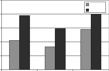
Figure 4.2 shows the influence of cutting speed and feed rate per tooth (f
z
) on
the surface finish obtained after endmilling quenched and tempered AISI H13
steel (average hardness of 47 HRC) using coated carbide inserts. It can be seen in
4 Surface Integrity 119
Figure 4.2 (a) that at a cutting speed of v
c
=
120
m/min surface roughness reaches
its lowest value, probably for the reasons previously discussed by [7]. As feed rate
per tooth increases, see Figure 4.2 (b), surface roughness is elevated drastically
owing to the higher distance between peaks and valleys. A more discrete effect is
observed when depth of cut (a
p
) is altered (Figure 4.2 (c)), i.e., higher R
a
values
are recorded when a
p
is increased due to the larger shear plane area, which re-
quires higher milling forces. Finally, Figure 4.2 (d) presents the influence of cut-
ting fluid applied under distinct machining conditions. When milder cutting pa-
rameters are selected, the roughness values are similar, however, under more
severe cutting conditions it seems that the use of cutting fluid presents a detrimen-
tal effect on surface finish. One possible reason for this behaviour may be the
increase in the thermal shock when cutting fluid is applied, which may accelerate
fatigue wear of the tool and impair surface finish.
As far as drilling of hardened steels is concerned, the amount of information
available in the published literature is considerably lower compared with turning
and milling. A number of reasons can be listed as constraints to drilling of hard
materials: variable cutting speed tending to zero at the centre of the drill, which
results in extruding (instead of shearing) the work material by the chisel edge;
variable rake, clearance and inclination angles together with small cross-section
0
0.05
0.1
0.15
0.2
0.25
vc (m/min)
Ra (um)
0
0.2
0.4
0.6
0.8
fz (mm/rev)
Ra (um)
0
0.1
0.2
0.3
0.4
ap (mm)
Ra (um)
0
0.4
0.8
1.2
1.6
2
21
Ra (um)
Dry cutting
Flooding
v
c
=70m/min
f
z
=0.05mm/rev
a
p
=0.5mm
v
c
=120m/min
f
z
=0.15mm/rev
a
p
=1.5mm
(i)
(ii)
(a)
(b)
(c)
(d)
Figure 4.2 Effect of cutting conditions on surface roughness of AISI H13 tool steel (47 HRC)
after endmilling using coated carbide inserts: (a) cutting speed; (b) feed rate; (c) depth o
f
cut; (d) cutting fluid ((i) v
c
=
70
m/min, f
z
=
0.05
mm/rev, a
p
=
0.5
mm; (ii) v
c
=
120m/min,
f
z
=
0.15
mm/rev, a
p
=
1.5
mm)
120 A.M. Abrão et al.
area of the drill, leading to insufficient torsional rigidity to cut this grade of mate-
rials. Despite the above-mentioned drawbacks, surface roughness values within
R
a
=
0.14–0.48 μm were obtained by [13] after drilling AISI H13 steel (hardness
range of 54–55 HRC) with coated solid carbide drills (8
mm diameter) at cutting
speeds from 20 to 45
m/min and feed rates of 0.1 and 0.2
mm/rev.
The development of computer-controlled three-dimensional profilemeters in
recent decades has allowed the use of this technique to characterize machined
surfaces more realistically. Waikar and Guo [14] compared the topography of
turned and ground hardened AISI 52100 steel (62 HRC) and reported that, addi-
tionally to the regular pattern produced on the surface by the combination of feed
rate and tool nose radius when turning (against the random pattern observed after
grinding), in general the surface produced by gentle grinding presented lower-
amplitude parameters (S
a
, S
q
, S
p
, S
v
, S
t
, and S
z
) compared with turning using fresh
and worn inserts and with dry grinding. As far as the functional parameters skew-
ness (S
sk
) and kurtosis (S
ku
) are concerned, only the surface generated by gentle
grinding presented negative S
sk
, thus indicating superior fluid retention ability,
while only abusive grinding produced a surface with S
ku
higher than three (height
distribution with low standard deviation).
The influence of the cutter path orientation on the surface texture of AISI H13
hot-work die steel (52 HRC) subjected to high-speed milling with coated tungsten
carbide ball-nose endmills was investigated by [15]. The angle between the work-
piece and the horizontal was 75° and the single raster and raster cutter strategies
were tested using the following orientations: vertical upward and downward and
horizontal upward and downward cutting. The findings indicated that the single
raster strategy with vertical upward cutter orientation gave best surface texture.
When a new cutter was employed, this condition produced well-defined isotropic
surfaces, whereas lowest surface roughness was obtained when a worn cutter was
used. Tool vibration, high milling forces and side flow were typical events that
impaired the quality of the surfaces produced by the other strategies.
The effect of cutting speed (40 and 60
m/min), tool wear (flank wear VB
B
=
0
and 0.2
mm) and cutting fluid pressure (ranging from 5 to 450
bar) on the surface
roughness obtained after turning Inconel 718 with carbide tools was investigated
by [16], who reported that R
a
values within 0.7 to 1
µm were obtained using a new
tool, irrespective of the remaining parameters. Not surprisingly, this value in-
creased with tool wear to reach values as high as R
a
=
3
µm.
Turning trials on Inconel 718 (44 HRC) using ceramic and PCBN inserts with
various geometries (square, round and triangular) and two edge preparations
(sharp edge with chamfer of 20°
×
0.1
mm and honed edge with chamfer of
15°
×
0.15
mm) were conducted by [17]. Lowest surface roughness values were
obtained using the round insert, due to the fact that its radius was 6
mm, while the
nose radius of the square and triangular inserts was r
ε
=
0.8
mm. In general, the
mixed-alumina insert provided lower R
a
values compared with the SiC-reinforced
alumina and PCBN tools, as well as the use of the honed edge.
Similar work was carried out by [18], who investigated the influence of the
geometry of coated carbide tools on the surface finish of solution annealed and
4 Surface Integrity 121
precipitation hardened Inconel 718 (35 HRC) after face-turning trials at v
c
=
60
m/min, f
=
0.1
mm/rev and a
p
=
0.5
mm. In general, lower surface roughness
was provided by the round inserts compared with the square inserts for the rea-
son previously explained (larger nose radius), as well as for inserts with honed
edge in comparison with sharp and chamfered edges. The reason for the poorer
surface finish obtained using chamfered tools was attributed to the higher cutting
forces and, in the case of sharp tools, excessive chipping of the cutting edge.
With regard to the rake angle, positive values provided better surface finish when
wet cutting, however, a negative rake angle allowed lower R
a
values when dry
turning. Finally, the use of cutting fluid resulted in superior surface finish owing
to the absence of a built-up edge.
Sharman et al. [19] assessed the effect of tool geometry and coating on the sur-
face texture of holes produced on Inconel 718 and found scattered R
a
values within
a range from 1 to 1.5
µm regardless of alterations on geometry and coating. How-
ever, as tool wear progressed, significant smearing was observed on the hole
walls. Subsequent reaming and boring improved surface finish drastically, provid-
ing average R
a
values below 0.5
µm.
4.1.2 Dimensional and Geometric Deviations
The static and dynamic stiffness of the machine-tool/workpiece pair are of great
importance, since vibration must be minimized during cutting. This can be
achieved through the proper design of bed ways and both headstock and tailstock
bearings. Additionally, high accuracy of the critical elements of the machine tool
is required in order to produce components with quality comparable with grinding.
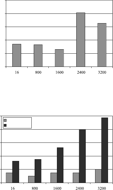
The influence of tool wear (measured in terms of length cut) on the dimen-
sional and geometric deviations after turning case-hardened DIN 19MnCr5 steel
using PCBN (v
c
=
180
m/min, f
=
0.08
mm/rot and a
p
=
0.15
mm) are presented in
Figures 4.3 and 4.4, respectively. Figure 4.3 shows that the dimensional deviation
for a given dimension observed during the first 1600
mm is minimal (correspond-
ing to ISO tolerance grade IT5); however, it increases drastically after this point,
probably due to the wear of the cutting tool.
As far as the geometric deviations are concerned, see Figure 4.4, distinct trends
are observed for roundness and concentricity, i.e., while a minimal variation of
4
µm is noted for roundness, the cylindricity deviation increases continuously with
length cut. Apparently, tool wear did not affect roundness to the same extent that it
affected concentricity, while the machine-tool condition could play a more rele-
vant role in concentricity.
Matsumoto et al. [20] compared the roundness deviation of bearing elements
(58–62 HRC) subjected to hard turning with PCBN and grinding (both followed
by superfinishing) and found that, owing to the accuracy of the machine tools
employed, tighter tolerances were obtained after hard turning, although the devia-
tions generated by operations were within the component tolerance range.
122 A.M. Abrão et al.
13
13.02
13.04
13.06
13.08
13.1
Length cut (mm)
Length (mm)
Figure 4.3 Effect of length cut on dimensional deviation when hard turning DIN 19MnCr5
steel using PCBN (v
c
=
180
m/min, f
=
0.08
mm/rot, and a
p
=
0.15
mm)
0
8
16
24
32
40
Length cut (mm)
Geomentric deviation (um)
Roundness
Concentricity
Figure 4.4 Effect of length cut on roundness and concentricity when hard turning DIN 19MnCr5
steel using PCBN (v
c
=
180
m/min, f
=
0.08
mm/rot, and a
p
=
0.15
mm)
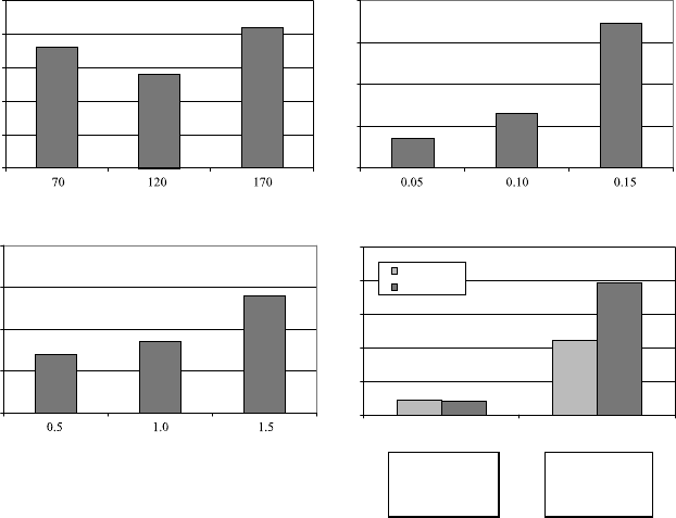
Figures 4.5 and 4.6 show, respectively, the dimensional and geometric devia-
tions observed after milling (v
c
=
120
m/min, f
=
0.1
mm/rot, a
p
=
0.5
mm and
a
e
=
5
mm) circular pockets on hardened H13 tool steel (41 HRC) using different
strategies and indexable tools. It can be seen in Figure 4.5 that the actual diame-
ter of the cavities was smaller than its nominal value (70
mm) due to tool de-
flection and that rather wide tolerances were produced.
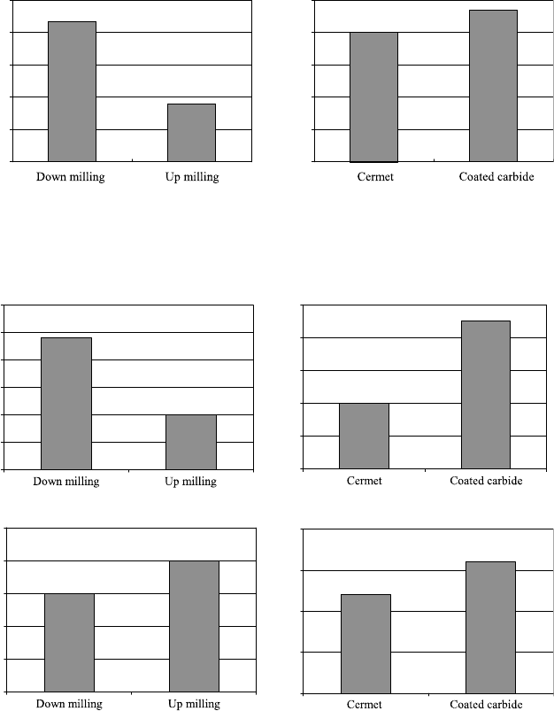
Figure 4.5 (a) shows that lower dimensional deviation is obtained when the
up-milling strategy is employed. The reason for that may reside in the higher
plastic deformation caused by the impact at the teeth entry when down-milling.
As far as the tool material is concerned, see Figure 4.5 (b), slightly lower devia-
tion was produced by the cermet, probably due to its superior wear resistance.
4 Surface Integrity 123
-250
-200
-150
-100
-50
0
Diameter deviation (um)
-100
-90
-80
-70
-60
-50
Diameter deviation (um)
(a)
(b)
Figure 4.5 Dimensional deviations obtained after milling circular pockets on hardened H13
steel: (a) effect of strategy, and (b) effect of tool material
0
5
10
15
20
25
30
Parallelism (um)
9.2
9.6
10
10.4
10.8
11.2
Parallelism (um)
0
3
6
9
12
15
Cylindricity (um)
0
5
10
15
20
Cylindricity (um)
(a) (b)
(c)
(d)
Figure 4.6 Geometric deviations obtained after milling circular pockets on hardened H13 steel:
(a) effect of strategy on parallelism; (b) effect of tool material on parallelism; (c) effect of strat-
egy on cylindricity; (d) effect of tool material on cylindricity
The same behaviour noted for the dimensional deviation was observed for par-
allelism (Figure 4.6 (a) and (b)), i.e., tighter tolerances were obtained when up-
milling with cermet; however, when considering the cylindricity deviation, down-
milling promoted a slightly better result than up-milling (Figure 4.6 (c)) and again
the cermet outperformed the coated carbide tool (Figure 4.6 (d)).
124 A.M. Abrão et al.
A geometric error of 25
µm was observed by [12] after high-speed milling
hardened hot-work die steel using PCBN inserts brazed on solid carbide ball-nose
endmills. As tool wear progressed, the error increased to 75
µm.
Coldwell et al. [13] investigated the quality of holes produced on hardened
AISI H13 hot-work steel (54–55 HRC) after drilling with AlTiN-coated solid
carbide tools with 8
mm diameter. Using an emulsion as cutting fluid (5
% concen-
tration), a diameter deviation of ±5
μm was obtained. Cylindricity values increased
with cutting speed, the best value being obtained for v
c
=
20
m/min (20.4
μm).
With regard to the roundness deviation, the values ranged from 2.85 to 17.75
μm.
4.2 Surface Alterations
According to Bellows and Tishler, cited in [21], there are five types of surface
alterations related to metal removal: mechanical (which include plastic deforma-
tion, built-up edge defects, hardness alteration, cracks, residual stresses, voids,
pits, burrs and inclusions), metallurgical (phase transformation, grain size and
distribution, precipitate size and distribution, foreign inclusions, twinning and
recrystallization, among others), chemical (such as intergranular attack, corrosion
and oxidation, preferential dissolution, contamination, enbrittlement by chemical
absorption and pits), thermal (including heat-affected zone and recast layer) and
electrical (conductivity and magnetic changes and resistive heating and overheat-
ing). In spite of the fact that this classification is quite useful and detailed, some
alterations cannot be classified in just one type. For instance, hardness alteration
may occur as a result of plastic deformation (mechanical type) and/or phase trans-
formation (metallurgical alteration).
Nevertheless, surface and subsurface alterations induced by hard-part machin-
ing are typically of mechanical, metallurgical and thermal nature. The presence
and extent of the alterations depend greatly on the severity of the machining op-
eration. The principal alterations observed on the surface layers of components
subjected to hard-part machining are presented below.
4.2.1 Microstructural Alterations
Microstructural changes in steels may be either mechanically or thermally in-
duced. In the case of hardenable steels, if the workpiece temperature exceeds the
austenization temperature during machining (due to friction and plastic strain),
austenite will be formed and, after quenched by the cold bulk material or by the
cutting fluid, a brittle, highly stressed and crack-prone martensite layer (usually
called a white layer) is formed at the surface. However, if the workpiece tempera-
ture exceeds the tempering temperature only, then overtempering will take place,
4 Surface Integrity 125
leading to the softening of the affected layers (identified as a dark layer after etch-
ing). Rech and Moisan [2] and Bosheh and Mativenga [22] claim that the forma-
tion of the white layer is a thermal process involving phase transformation and,
probably plastic deformation, which has not been fully understood yet.
Turning tests on hardened AISI H13 tool steel (54–56 HRC) with PCBN inserts
indicated that the hardness and depth of the white layer decreased as cutting speed
was elevated owing to a slight reduction in the workpiece temperature [22]. In
contrast, Axinte and Dewes [23] assert that neither a white layer nor a heat-
affected zone were observed after high-speed milling AISI H13 hot-work die steel
hardened to 47–49 HRC with TiAlN coated carbide ball-nose endmills. This dif-
ference can be explained by the fact that in the former work cutting speeds of 100,
400 and 700
m/min were tested, the thickest white layer being observed at the
lowest cutting speed. For cutting speeds of 400 and 700
m/min, the depth of the
white layer decreased dramatically. In the case of the latter work, cutting speeds of
200 and 300
m/min were used, which seem to be above the critical value required
for the formation of the white layer.
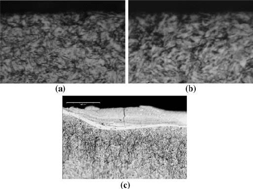
Figure 4.7 presents cross-section samples of AISI H13 tool steel (47 HRC) after
dry endmilling under gentle conditions (Figure 4.7 (a)), grinding with a CBN wheel
(Figure 4.7 (b)) and die-sinking EDM using copper electrodes (Figure 4.7
(c)).
Similarly to the work reported by [23], the samples subjected to milling and grinding
do not show any evidence of alteration. Conversely, cracks, recast layer and heat-
affected zone are visible in the sample subjected to EDM. As a consequence, one
would expect a similar behaviour of the components produced through endmilling
and grinding with regard to their service life, both outperforming the part produced
by EDM.
Figure 4.7 Microstructure of hardened AISI H13 after machining using distinct operations: (a)
endmilling (×1000), (b) grinding (×1000), and (c) die sinking EDM (×500)
126 A.M. Abrão et al.
The occurrence of the white layer in AISI 52100 bearing steel hardened to
63 HRC after turning with PCBN and grinding with an alumina wheel under abu-
sive cutting conditions was studied by [24]. In order to promote the generation of
the white layer, the turning and grinding tests were conducted dry using a worn
PCBN tool and a worn alumina wheel, respectively. Both operations resulted in
a white layer followed by a dark layer before the bulk material, however, the
thickness of the layers was considerably larger when the abrasive process was
employed. Additionally, the white layer produced by turning was etch resistant,
while the microconstituents were visible in the sample generated by grinding (fer-
rite matrix plus cementite particles without evidence of severe strain). The authors
claim that the etching resistance of the turned sample may be attributed to the
presence of nanograins (100–300
nm) resulting from dynamic recovery and recrys-
tallization.
Furthermore, the volume fraction of retained austenite in the white and dark
layer was 10.64
% for the turned sample and 2.88
% for the ground sample,
whereas in the dark layer the values found were 11.68
% and 0
%, respectively.
The high volume of retained austenite observed in the white layer of the turned
specimen suggests that severe plastic strain took place during machining. More-
over, these findings indicate that the temperature reached in the ground dark layer
was high enough for tempering, but not to form austenite.
The volume fraction of retained austenite on the surface of hard-turned cold-
work steel is reported to be twice the amount found in the bulk material [25]. The
authors state that the generation of a white layer after machining is the result of
a combination of the thermal effect and plastic deformation. Under circumstances
in which the austenisation temperature is not reached, the thermal effect causes the
softening of the material, thus leading to severe plastic deformation and the forma-
tion of a nanocrystalline white layer. As a result of the softening, an overtempered
martensitic layer is observed below the white layer.
The influence of the cutting-edge preparation on the plastic deformation in-
duced by the cutting tool when turning hardened AISI 52100 bearing steel (aver-
age values of 41 and 57 HRC) was investigated by [26]. Low-content PCBN
inserts with three distinct edge preparations were tested: sharp (average honed
edge radius of r
h
=
22.9
μm), honed edge (r
h
=
100–150
μm) and chamfered
(115
μm
×
17° plus r
h
=
25.4
μm). The metallographic analysis indicated that sub-
surface plastic flow occurred only after machining using the insert with larger
hone edge (r
h
=
100–150
μm). Furthermore, deeper subsurface plastic deformation
was associated with the presence of larger compressive residual stresses.
A direct relationship between the presence of the white layer on the machined
subsurface and both edge preparation and depth of cut was reported by [27], who
noticed that when turning AISI 52100 bearing hardened to 60–62 HRC with
PCBN inserts, the combination of large edge hone radius (r
h
=
70
μm) and high
depth of cut (a
p
=
0.255
mm) results in the formation of an untempered martensite
layer followed by an overtempered martensite layer, not present either after turn-
ing with tools possessing low edge radius (r
h
=
25
μm) at low depth of cut
(a
p
=
0.051
mm), or after grinding and superfinishing.