Davim J.P.Machining of Hard Materials
Подождите немного. Документ загружается.

2 Advanced Cutting Tools 57
sists of the injection of a high-speed air jet with micro-drops of biodegradable oil
in suspension.
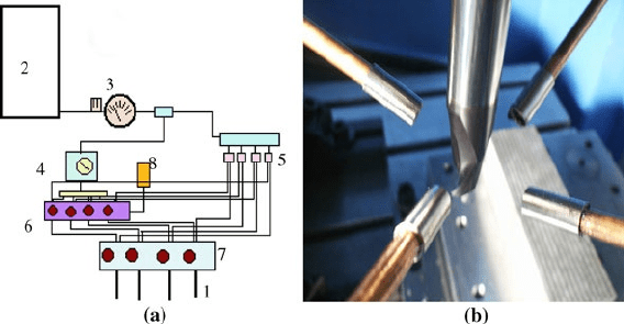
A typical and modern MQL system is detailed in Figure 2.22. The system oper-
ates with pressurized air (10–12
bars). The pressurized air arrives to the system
and it enters a maintenance unit (2); afterwards the air goes through a pressure
regulator (3). Then, part of the air arrives to a subsystem where it produces the
impulsion of the oil, regulated through a frequency meter (4) and several pumps
(6) which provide the quantity of oil to be supplied by each nozzle at each instant.
Oil is impelled up to the nozzle (1), where the mixture of oil with air is produced.
The simultaneous effect of pressure and speed of the air in the exit nozzle sprays
the oil. The obtained oil drops are below 2
μm diameter.
In the machining of hardened and tempered steels (more than 40 HRC in finish-
ing conditions) dry or near to dry machining is a common option. In addition, the
pressurized air injection is used to take away chips from the cutting zone. Cryo-
genic cooling by means of liquid nitrogen is now researched for titanium and
nickel alloys [9]. However when difficult-to-cut alloys are machined the most
common technique is the emulsion coolant, 5–10
% oil in water.
2.5 Tool Geometry
A cutting tool presents a main cutting edge and several faces. Many tools have
another secondary cutting edge (minor edge). The shape of edges and angles be-
tween faces influence the machining performance greatly. In Figure 2.23 the basic
geometry for a single-point cutting tool (that is, a turning tool) and for a multiple-
point cutting tool (an endmilling tool in this case) are shown.
The definition of tool geometry is explained in the ISO 3002/1 [10]. Here two
reference systems are described: tool-in-hand and tool-in-use.
Figure 2.22 (a) Configuration of an MQL system, and (b) detail of the nozzles, four in this case
58 L.N. López de Lacalle et al.
Clearance face
Main edge
Minor edge
Corner radius
Rake face
d
Minor edge
Main edge
Rake face
Clearance
face
(a)
(b)
Figure 2.23 Basic geometry for (a) turning and (b) endmilling tools
In the tool-in-hand reference system three planes are defined:
• P
r
: tool reference plane, parallel to the tool base or contains the axis of the
rotational tool;
• P
f
: assumed working plane, perpendicular to P
r
and contains the feed direction;
• P
p
: tool back plane, perpendicular to P
r
and P
f
;
• P
n
: edge normal plane, perpendicular to the edge in each point.
In Figure 2.24, P
r
, P
f
and P
p
for a turning and a milling tool are shown. Using
these planes several angles are measured:
•
κ
r
: position edge angle (measured in P
r
);
•
κ
′
r
: position edge angle of the minor edge (measured in P
r
);
•
γ
n
: normal rake angle (measured in P
n
);
•
α
n
: normal clearance (measured in P
n
);
•
λ
s
: edge inclination angle (measured in P
s
).
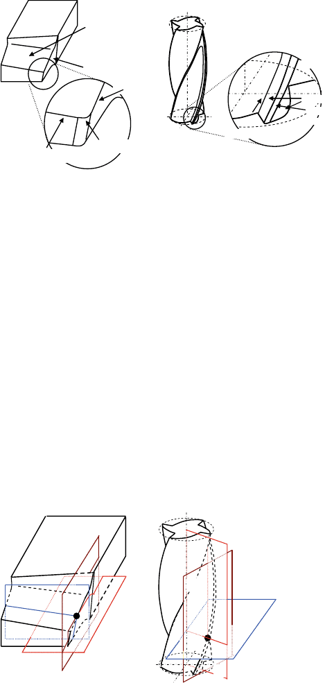
(a)
(b)
Pr: Reference plane for the tool
Pf: Assumed working plane
Pp: Tool back plane
Pr
Pf
Pp
Pr
Pf
Pp
Figure 2.24 Tool-in-hand reference system for (a) turning and (b) milling tools
2 Advanced Cutting Tools 59
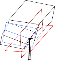
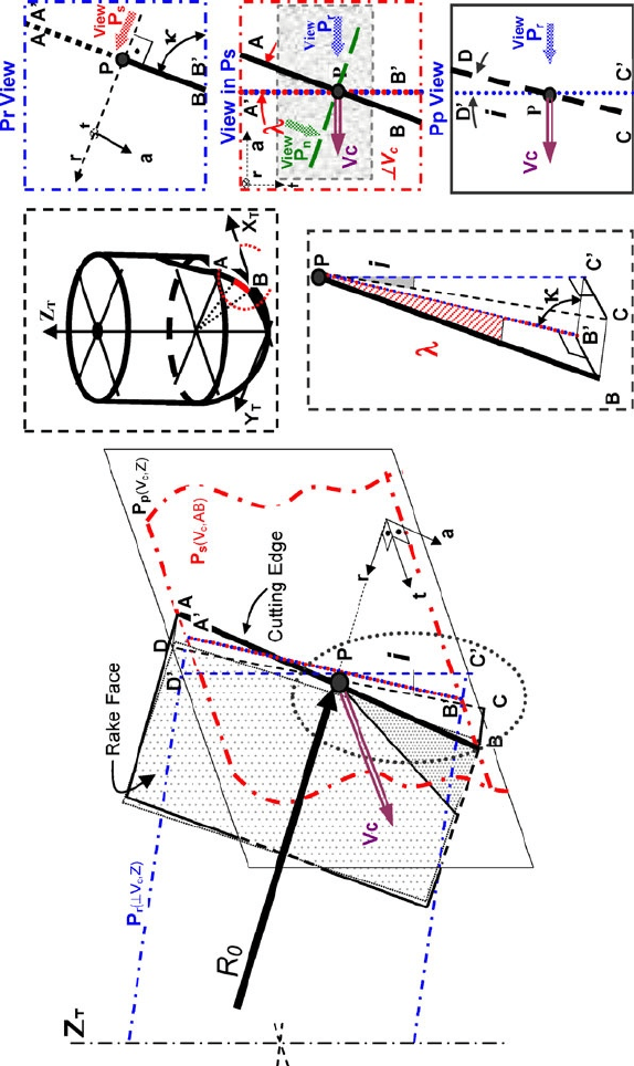
Figure 2.25 Tool-in-use reference system for a turning tool
Pr
e
: Reference plane
Pf
e
: Working plane
Pp
e
: Tool back plane
Vc
e
Pr
e
Pf
e
Pp
e
In Figures 2.27 and 2.28 the reference system is applied to and endmill and ball
mill, respectively [11].
In the case of the tool-in-use reference system the main direction is given by
the effective cutting speed (i.e., the sum of the cutting speed and feed). Here three
main planes are defined (see Figure 2.25):
• P
re
: working reference plane, defined by the edge point and perpendicular to the
effective cutting speed;
• P
fe
: working plane, contains the cutting speed and feed vectors and is perpen-
dicular to the reference plane;
• P
pe
: tool back plane, perpendicular to P
re
and P
fe
.
2.5.1 Endmilling Tools
A main difference between endmills and ball-endmills is the helix angle variation
along the cutting edge. Even though the possibility that the flutes of a ball-endmill
may be with a constant helix angle, most of the tools in the market present con-
stant lead, resulting in a variable helix angle. This is due to the usual grinding
process applied for the fabrication of this kind of tool. Another consequence of the
grinding process is that the normal rake and relief angles are made constant along
the cutting edge.
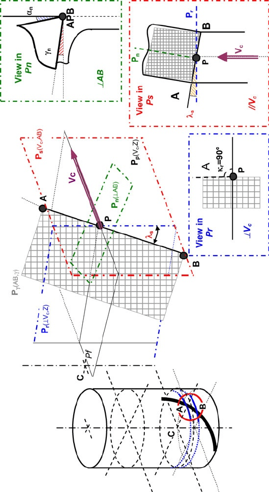
Thus, the spatial generation of the edge is the result of projecting a cylindrical
helix on a sphere perpendicularly to the axis of the tool direction. The resulting
cutting-edge geometry is shown in detail in Figure 2.27. Here, cutting-edge angles
have been measured following ISO nomenclature. The inclination angle,
λ
s
, is
measured in the P
s
plane (defined by cutting-edge discrete element AB and the
cutting-speed vector V
c
), and it is the angle formed by the cutting speed V
c
and the
cutting edge AB. Local helix angle, represented as i, is measured on the P
p
plane
(defined by V
c
vector and Z-axis).
In cylindrical endmills (see Figure 2.26), the inclination angle of the edge coin-
cides with the helix angle, since the tangent plane to the edge is always parallel to the
tool axis.
60 L.N. López de Lacalle et al.
Figure 2.26 Geometry of an endmill
2 Advanced Cutting Tools 61
Figure 2.27 Geometry of a ball-endmill
62 L.N. López de Lacalle et al.
2.5.2 The Rake and Clearance Angles
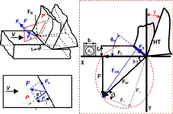
In oblique cutting, machining forces are composed of three components, instead of
the two of orthogonal cutting. The geometry and angles of a cutting tool defines
the values of each of the components, in addition to the characteristic shear angle
Φ
of the material and the inclination angle of the cutting edge with respect to the
cutting speed, i. In Figure 2.28 the cutting-force components are described.
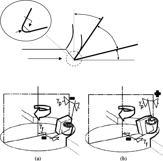
However, the most important concepts to evaluate in all the machining opera-
tions under a qualitative point of view are those presented in Figure 2.29: the
clearance angle, the rake angle and the edge angle.
The rake angle shown in this figure is positive, the most common case, but in
hard machining it could be negative, with the tool oriented towards the cutting-
speed direction. Since clearance angle always must be positive to avoid rubbing on
the part surface, a negative rake angle implies a very strong cutting edge, and
therefore is recommended for very difficult-to-cut materials where cutting forces
are much too high. Another aspect to bear in mind is the so-called edge radius,
different from the corner radius (where the main and minor edges intersect). The
edge radius is only few hundredths of a millimetre, and in some cases, as in PCBN
inserts, a chamfer is produced instead of the rounded edge.
In milling tools both the mean and minor edges have a big influence on tool
performance. Therefore the radial and axial rake and clearance angles must be
considered. Several combinations could be used; in Figure 2.30 two of them are
shown. The first situation in the figure is very aggressive, due to the both negative
angles. The second situation is a good combination because the positive axial
angle allows chip was evacuated out from the part surface, and the negative radial
angle permits a very robust tool edge design.
Figure 2.28 Geometry of the oblique cutting, with the decomposition of the cutting force in the
main directions
2 Advanced Cutting Tools 63
Clearance angle
Rake angle (+)
Edge angle
Vc
r
Edge radius
or chamfer
Figure 2.29 Basic angles for a rapid tool evaluation
Figure 2.30 (a) Axial and (b) radial rake angles (courtesy of Sandvik Coromant)
2.5.3 Position Angle
The tool cutting-edge angle (
κ
r
) has a direct influence on chip thickness and there-
fore on the cutting-force components. At the same feed rate, decreasing the side
cutting-edge angle increases the chip contact length and decreases chip thickness.
As a result, the cutting force is dispersed on a longer cutting edge and tool life is
prolonged.
Increasing the side cutting-edge angle increases chip width. Therefore, decreas-
ing the position angle is recommended for:
• hard workpieces which produce high cutting temperature due to their high spe-
cific cutting forces;
• when roughing a large-diameter workpiece.
2.5.4 Milling Tools for Several Applications
Bearing in mind the geometry possibilities for milling tools and requirements
derived from the workpiece hardness, shape and dimensions, big manufacturers of
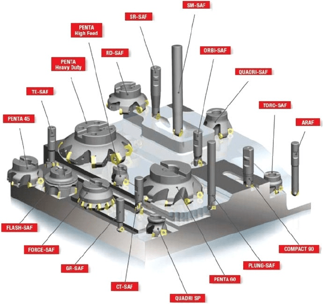
64 L.N. López de Lacalle et al.
tools offer a complete catalogue of milling tools. In Figure 2.31 the milling op-
tions provided by the tool manufacturer Safety
®
are represented, including milling
discs with inserts with different lead angles for facing, insert tools with lead angle
90° for slotting and shouldering, and ball-endmilling tools.
2.6 Hard Machining for Mould and Dies
Before the generalized use of high-speed milling, the usual technology employed
in mould manufacture was a combination of conventional milling and electrodis-
charge machining [12, 13]. From 1997 to 1999 roughing and semi-finishing were
usually carried out with conventional machines, with mould steel in a soft state
before tempering. Subsequently, heat treatment was applied. After that, finishing
was performed in high-speed machining centres. There were two reasons for such
a sequence:
Figure 2.31 Milling tools supplied by Safety
®
2 Advanced Cutting Tools 65
• Roughing, which is subject to few precision requirements, was done in ma-
chines which cost per hour one-fifth of high-speed machines. Moreover, tool
wear was light because of the low hardness of the workpiece material.
• The most usual high-speed spindles available in those days were unable to
deliver sufficient torque below 1500
rpm, making roughing impossible.
In 2000, technical variations made to high-speed spindles control resulted in an
improved capacity to deliver enough torque even at low rotational speeds. In this
manner, roughing in high-speed machines became possible, with a similar applica-
tion practice to the conventional case. Therefore, a new procedure was defined
starting directly from a block initially heat-treated, carrying out consecutively all
operations in the same machine. The mean advantages of this simpler process was
that less time was needed to launch a new mould, since between successive opera-
tions there was less time needed for set-up. At the same time, accuracy and reli-
ability of workpiece also increased, due to the avoidance of workpiece zero setups
between operations.
At present, the decision whether to use high-speed machines starting from tem-
pered raw material, or conventional roughing of non-tempered steel followed by
tempering and high-speed milling, depends on production costs and required lead
times. But in all the cases finishing is performed by ball-end high-speed milling.
2.6.1 Ball-endmilling for Sculptured Surfaces
High-speed milling with ball-endmills is the basic technology for finishing
complex surfaces, the final and high-added-value stage when complex forms are
produced [12, 14–16].
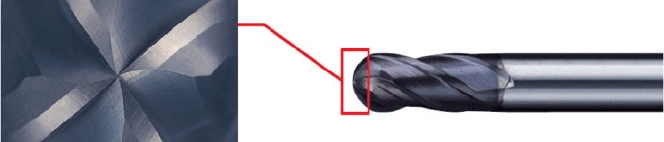
In Figure 2.32 a typical ball-endmilling tool for finishing hard steels is shown.
A four-flute geometry with a full cutting edge to the centre of the ball, in combi-
nation with an improved version of TiAlN coating (more than 3700
HV hardness)
provides the necessary efficiency of cutting together with high heat and wear
resistance.
This operation commonly involves the milling of a 0.3
mm allowance (as
shown in Table 2.6), which is usually done using ball-endmills with diameter
below 20
mm, due to the intricate shape details. Taking into account that slopes
Figure 2.32 The VF4MB by Mitsubishi
®
, 4 flute geometry with a full cutting edge to the centre
of the ball
66 L.N. López de Lacalle et al.
commonly found in sculptured forms go from 0° to 90° and that effective cut-
ting speed must be between 300 and 400
m/min – this is the maximum recom-
mended for the current carbide tools coated with AlTiN – the spindle rotational
speed must be over 15,000
rpm. This means that high-speed spindles must be
used. Nowadays, the maximum rotational speed of industrial electrospindles is
around 20,000–25,000
rpm, with power ranging from 14 to 20
KW.
On the other hand, for this rotational speed, and bearing in mind a recommended
feed of around 0.07–0.1
mm/tooth, the maximum linear feed is 10–15
m/min.
These values can be obtained by typical linear ball screws connected to synchro-
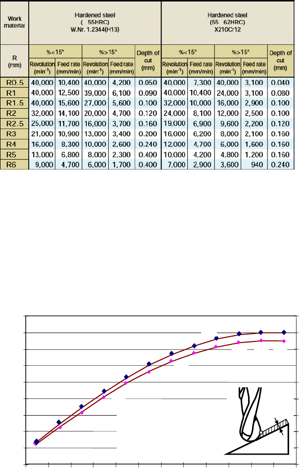
Table 2.6 Cutting conditions recommended by Mitsubishi
®
for the VF4MB
3.5
5.5
7.4
9.2
10.8
12.3
13.5
14.5
15.2
16
15.7
261
351
167
752
743
720
685
638
580
512
435
0
2
4
6
8
10
12
14
16
18
0 7.5 15 22.5
3
37.5 45 52.5
60
Workpiece slope (º)
Effective diameter (mm)
600
700
800
∅
16mm, 15,000 rpm
a
p
0.2 mm ,a
e
0.2 mm
Vc
nominal
753 m/min
f
z
0.1 mm/z,F 3000 mm/min
Effective Cutting speed (m/min)
67.5
75
82.5
0
100
200
300
400
500
90
a
p
A
753
13.9
Figure 2.33 Effective tool diameter and cutting speed for different surface inclinations, using
a ball-endmilling tool. A is the point of maximum cutting speed