Czichos H., Saito T., Smith L.E. (Eds.) Handbook of Metrology and Testing
Подождите немного. Документ загружается.


XXX List of Abbreviations
NDP neutron depth profiling
NDT nondestructive testing
NEP noise-equivalent power
NEXAFS near-edge x-ray absorption fine structure
NFPA National Fire Protection Association
NHE normal hydrogen electrode
NIR near infrared
NIST National Institute of Standards and
Technology
NMI National Metrology Institute
NMR nuclear magnetic resonance
NMi Netherlands Measurement Institute
NOE nuclear Overhauser effect
NPL National Physical Laboratory
NPT number pressure temperature
NR natural rubber
NR neutron reflectance
NRA nuclear reaction analysis
NRC-CRM National Research Center for Certified
Reference Materials
NRW Nordrhein-Westfalen
NTC negative temperature coefficient
O
OA operational amplifier
OCT optical coherence tomography
ODD object-to-detector distance
ODF orientation distribution function
ODMR optically detected magnetic resonance
ODS octadecylsilane
OES optical emission
spectroscopy/spectrometry
OIML International Organization of Legal
Metrology
OKE optical Kerr effect
OM optical microscopy
OMH Orzajos Meresugyi Hivatal
OPA optical parametric amplifier
OPG optical parametric generation
OPO optical parametric oscillator
OR optical rectification
ORD optical rotary dispersion
OSA optical spectrum analyzer
OSU Ohio State University
OTDR optical time-domain reflectometry
P
PA polyamide
PAA photon activation analysis
PAC Pacific Accreditation Cooperation
PAC perturbed angular correlation
PAH polycyclic aromatic hydrocarbon
PAS positron annihilation spectroscopy
PBG photonic band gap
PC personal computer
PC photoconductive detector
PC polycarbonate
PCB polychlorinated biphenyl
PCF photonic crystal fiber
PCI phase contrast imaging
PCR polymerase chain reaction
PDMS poly(dimethylsiloxane)
PE polyethylene
PE-HD high-density polyethylene
PE-LD low-density polyethylene
PEELS parallel electron energy loss spectroscopy
PEM photoelectromagnetic
PERSF pure element relative sensitivity factor
PET polyethylene terephthalate
PFM pulse field magnetometer
PGAA prompt gamma activation analysis
PHB poly(β-hydroxy butyrate)
PI pitting index
PID photoionization detector
PIRG path-integral renormalization group
PIXE particle-induced x-ray emission
PL photoluminescence
PLE PL excitation
PLZT lanthanide-modified piezoceramic
PM polymer matrix
PMMA poly(methyl methacrylate)
PMT photomultiplier tube
POD probability of detection
POF polymer optical fiber
POL polychromator
POM particulate organic matter
POS proof-of-screen
PSD power-spectral density
PSDF power spectral density function
PSI phase-shift interferometry
PSL photostimulated luminescence
PT phototube
PTB Physikalisch-Technische Bundesanstalt
PTC positive temperature coefficient
PTFE polytetrafluoroethylene
PTMSP poly(1-trimethlsilyl-1-propyne)
PU polyurethane
PUF polyurethane foam
PV photovoltaic
PVA polyvinyl acetate
PVC polyvinyl chloride
PVD physical vapor deposition
PVDF polyvinylidene fluoride
PWM pulse-width modulation
PZT lead zirconate titanate
Q
QA quality assurance
QC quality control

List of Abbreviations XXXI
QE quantum effect
QMR quasiminimal residual
QMS quality management system
QNMR quantitative proton nuclear magnetic
resonance
R
RAPD random amplified polymorphic DNA
RBS Rutherford backscattering
RC resistor–capacitor
RD rolling direction
RDE rotating disc electrode
RE reference electrode
RF radiofrequency
RFLP restriction fragment length polymorphism
RG renormalization group
RH relative humidity
RI refractive index
RM reference material
RMO regional metrology organization
RMR RM report
RMS root mean square
RNA nuclear reaction analysis
RNAA radiochemical NAA
RPLC reversed-phase liquid chromatography
RRDE rotating ring-disc electrode
rRNA ribosomal RNA
RSF relative sensitivity factor
S
S/N signal-to-noise ratio
SABS South African Bureau of Standards
SAD selected area diffraction
SADCMET Southern African Development
Community Cooperation in Measurement
Traceability
SAMR small-angle magnetization-rotation
SAQCS sampling and analytical quality control
scheme
SAXS small-angle x-ray scattering
SBI single burning item
SBR styrene butyl rubber
SBS sick-building syndrome
SC superconductivity
SCA surface chemical analysis
SCC stress corrosion cracking
SCE saturated calomel electrode
SCLM scanning confocal laser microscopy
SD strength difference
SDD silicon drift detector
SE secondary electron
SEC specific energy consumption
SECM scanning electrochemical microscope
SEI secondary electron imaging
SEM scanning electron microscopy
SEN single-edge notched
SENB4 four-point single-edge notch bend
SER specific emission rate
SFG sum frequency generation
SFM scanning force microscopy
SHE standard hydrogen electrode
SHG second-harmonic generation
SHM structural health monitoring
SI International System of Units
SI Système International d’Unités
SIM Sistema Interamericano de Metrología
SIMS secondary ion mass spectrometry
SMSC study semiconductor
SMU Slovenski Metrologicky Ustav
SNOM scanning near-field optical microscopy
SNR signal-to-noise ratio
SOD source-to-object distance
SOLAS safety of life at sea
SOLZ second-order Laue zone
SOP standard operating procedure
SOR successive overrelaxation
SP Swedish National Testing and Research
Institute
SPD singular point detection
SPF superplastic forming
SPH smooth particle hydrodynamics
SPI selective polarization inversion
SPM scanning probe microscopy
SPM self-phase modulation
SPOM surface potential microscope
SPRT standard platinum resistance thermometer
SPT sampling proficiency test
SQUID superconducting quantum interference
device
SRE stray radiant energy
SRET scanning reference electrode technique
SRM standard reference material
SRS stimulated Raman scattering
SS spectral sensitivity
SSE stochastic series expansion
SST single-sheet tester
SST system suitability test
STEM scanning transmission electron
microscopy
STL stereolithographic data format
STM scanning tunneling microscopy
STP steady-state permeation
STS scanning tunneling spectroscopy
SUPG streamline-upwind Petrov–Galerkin
SVET scanning vibrating electrode technique
SVOC semi-volatile organic compound
SW Swendsen–Wang
SWLI scanning white-light interferometry
SZ stretched zone
SZW stretched zone width

XXXII List of Abbreviations
T
TAC time-to-amplitude converter
TBCCO tellurium-barium-calcium-copper-oxide
TBT technical barriers to trade
TCD thermal conductivity detector
TCSPC time-correlated single-photon counting
TDI time-delayed integration
TDS thermal desorption mass spectrometry
TDS total dissolved solid
TEM transmission electron microscopy
TFT thin-film transistor
TG thermogravimetry
TGA-IR thermal gravimetric analysis-infrared
TGFSR twisted GFSR
THG third-harmonic generation
TIMS thermal ionization mass spectrometry
TIRFM total internal reflection fluorescence
microscopy
TLA thin-layer activation
TMA thermomechanical analysis
TMR tunnel magneto-resistance
TMS tetramethylsilane
TOF time of flight
TPA two-photon absorption
TR technical report
TRIP transformation induced plasticity
TS tensile strength
TTT time–temperature-transformation
TU Technical University
TVOC total volatile organic compound
TW thermostat water
TWA technical work area
TWIP twinning induced plasticity
TXIB 2,2,4-trimethyl-1,3-pentanediol
diisobutyrate
TXRF total reflection x-ray fluorescence
spectrometry
U
UBA Bundesumweltamt
UHV ultra-high vacuum
UIC Union Internationale des Chemins de Fer
ULSI ultralarge-scale integration
USAXS ultrasmall-angle scattering
USP United States Pharmacopeia
UT ultrasonic technique
UTS ultimate tensile strength
UV ultraviolet
UVSG UV Spectrometry Group
UXO unexploded ordnance
V
VAMAS Versailles Project on Advanced Materials
and Standards
VCSEL vertical-cavity surface-emitting laser
VDEh Verein Deutscher Eisenhttenleute
VG vortex glass
VIM international vocabulary of basic and
general terms in metrology
VIM international vocabulary of metrology
VL vortex liquid
VOC volatile organic carbon
VOST volatile organic sampling train
VSM vibrating-sample magnetometer
VVOC very volatile organic compound
W
WDM wavelength division multiplexing
WDS wavelength-dispersive spectrometry
WE working electrode
WFI water for injection
WGMM Working Group on Materials Metrology
WHO World Health Organization
WLI white-light interferometry
WTO World Trade Organization
WZW Wess–Zumino–Witten
X
XAS x-ray absorption spectroscopy
XCT x-ray computed tomography
XEDS energy-dispersive x-ray spectrometry
XFL photoemitted Fermi level
XMA x-ray micro analyzer
XMCD x-ray magnetic circular dichroism
XPS x-ray photoelectron spectroscopy
XPS x-ray photoemission spectroscopy
XRD x-ray diffraction
XRF x-ray fluorescence
XRT x-ray topography
Y
YAG yttrium aluminum garnet
YIG yttrium-iron garnet
YS yield strength
Z
ZOLZ zero-order Laue zone
ZRA zero-resistance ammetry

1
Fundame
Part A
Part A Fundamentals of Metrology and Testing
1 Introduction to Metrology and Testing
Horst Czichos, Berlin, Germany
2 Metrology Principles and Organization
Andrew Wallard, Sèvres, France
3 Quality in Measurement and Testing
Michael H. Ramsey, Brighton, UK
Stephen L.R. Ellison, Middlesex, UK
Horst Czichos, Berlin, Germany
Werner Hässelbarth, Berlin, Germany
Hanspeter Ischi, Berne, Switzerland
Wolfhard Wegscheider, Leoben, Austria
Brian Brookman, Bury, Lancashire, UK
Adolf Zschunke, Leipzig, Germany
Holger Frenz, Recklinghausen, Germany
Manfred Golze, Berlin, Germany
Martina Hedrich, Berlin, Germany
Anita Schmidt, Berlin, Germany
Thomas Steiger, Berlin, Germany


3
Introduction t
1. Introduction to Metrology and Testing
This chapter reviews the methodologies of mea-
surement and testing. It gives an overview of
metrology and presents the fundamentals of
materials characterization as a basis for
1. Chemical and microstructural analysis
2. Materials properties measurement
3. Materials performance testing
which are treated in parts B, C, and D of the
handbook.
1.1 Methodologies of Measurement
and Testing.......................................... 3
1.1.1 Measurement .............................. 3
1.1.2 Testing........................................ 5
1.1.3 Conformity Assessment
and Accreditation......................... 7
1.2 Overview of Metrology .......................... 9
1.2.1 The Meter Convention ................... 9
1.2.2 Categories of Metrology................. 9
1.2.3 Metrological Units ........................ 11
1.2.4 Measurement Standards ............... 12
1.3 Fundamentals
of Materials Characterization ................. 13
1.3.1 Nature of Materials....................... 13
1.3.2 Types of Materials ........................ 15
1.3.3 Scale of Materials ......................... 16
1.3.4 Properties of Materials .................. 17
1.3.5 Performance of Materials .............. 19
1.3.6 Metrology of Materials .................. 20
References .................................................. 22
In science and engineering, objects of interest have to
be characterized by measurement and testing. Measure-
ment is the process of experimentally obtaining quantity
values that can reasonably be attributed to a property of
a body or substance. Metrology is the science of mea-
surement. Testing is the technical procedure consisting
of the determination of characteristics of a given object
or process, in accordance with a specified method [1.1].
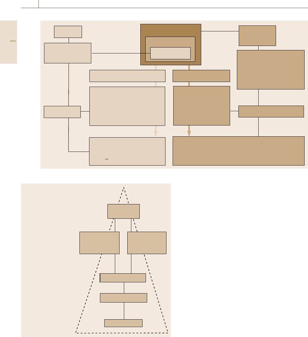
1.1 Methodologies of Measurement and Testing
The methodologies of measurement and testing to deter-
mine characteristics of a given object are illustrated in
a unified general scheme in Fig. 1.1, which is discussed
in the next sections.
1.1.1 Measurement
Measurement begins with the definition of the mea-
surand, the quantity intended to be measured. The
specification of a measurand requires knowledge of the
kind of quantity and a description of the object car-
rying the quantity. When the measurand is defined, it
must be related to a measurement standard, the realiza-
tion of the definition of the quantity to be measured.
The measurement procedure is a detailed description
of a measurement according to a measurement princi-
ple and to a given measurement method. It is based
on a measurement model, including any calculation
to obtain a measurement result. The basic features of
a measurement procedure are the following [1.1].
•
Measurement principle: the phenomenon serving as
a basis of a measurement
•
Measurement method: a generic description of
a logical organization of operations used in a mea-
surement
•
Measuring system: a set of one or more measur-
ing instruments and often other devices, including
any reagent and supply, assembled and adapted to
give information used to generate measured quan-
Part A 1
4 Part A Fundamentals of Metrology and Testing
SI units
Measurement
standard
Calibration
OBJECT
Characteristics
Measurand
Testing procedure
Test principle
Test method
Instrumentation
Quality assurance
Reference
material
Chemical composition,
geometry, structure,
physical properties,
engineering properties,
other
Reference procedure
Testing result: Specified characteristic of an
object by qualitative and quantitative means,
and adequately estimated uncertainties
Measurement procedure
Measurement principle
Measurement method
Measuring system
Measurement uncertainty
Measurement result:
Quantity value
1 uncertainty (unit)
Fig. 1.1 The methodologies of measurement (light brown) and testing (dark brown) – a general scheme
BIPM
Bureau International des
Poids et Mésures
National metrology
institutes or designated
national institutes
Calibration laboratories,
often accredited
Industry, academia,
regulators, hospitals
End users
Definition
of the unit
Foreign
national primary
standards
National
primary
standards
Reference standards
Working standards
Measurements
Fig. 1.2 The traceability chain for measurements
tity values within specified intervals for quantities
of specified kinds
•
Measurement uncertainty: a nonnegative parameter
characterizing the dispersion of the quantity values
being attributed to a measurand
The result of a measurement has to be expressed as
a quantity value together with its uncertainty, including
the unit of the measurand.
Traceability and Calibration
The measured quantity value must be related to a ref-
erence through a documented unbroken traceability
chain. The traceability of measurement is described in
detail in Sect.3.2. Figure 1.2 illustrates this concept
schematically.
The traceability chain ensures that a measurement
result or the value of a standard is related to references
at the higher levels, ending at the primary standard,
based on the International System of Units (le Sys-
tème International d’Unités, SI) (Sect. 1.2.3). An end
user may obtain traceability to the highest interna-
tional level either directly from a national metrology
institute or from a secondary calibration laboratory, usu-
ally an accredited laboratory. As a result of various
mutual recognition arrangements, internationally rec-
ognized traceability may be obtained from laboratories
outside the user’s own country. Metrological timelines
in traceability, defined as changes, however slight, in
Part A 1.1

Introduction to Metrology and Testing 1.1 Methodologies of Measurement and Testing 5
all instruments and standards over time, are discussed
in [1.2].
A basic tool in ensuring the traceability of a mea-
surement is either the calibration of a measuring
instrument or system, or through the use of a reference
material. Calibration determines the performance char-
acteristics of an instrument or system before its use,
while reference material calibrates the instrument or
system at time of use. Calibration is usually achieved
by means of a direct comparison against measurement
standards or certified reference materials and is docu-
mented by a calibration certificate for the instrument.
The expression “traceability to the SI” means trace-
ability of a measured quantity value to a unit of the
International System of Units. This means metrologi-
cal traceability to a dematerialized reference, because
the SI units are conceptually based on natural con-
stants, e.g., the speed of light for the unit of length.
So, as already mentioned and shown in Fig. 1.1,the
characterization of the measurand must be realized by
a measurement standard (Sect. 1.2.4). If a measured
quantity value is an attribute of a materialized object
(e.g., a chemical substance, a material specimen or
a manufactured product), also an object-related trace-
ability (speciation) to a materialized reference (Fig. 1.1)
is needed to characterize the object that bears the metro-
logically defined and measured quantity value.
Uncertainty of Measurements
Measurement uncertainty comprises, in general, many
components and can be determined in different
ways [1.3]. The Statistical Evaluation of Results is ex-
plained in detail in Sect. 3.3,andtheAccuracy and
Uncertainty of Measurement is comprehensively de-
scribed in Sect. 3.4. A basic method to determine
uncertainty of measurements is the Guide to the expres-
sion of uncertainty in measurement (GUM)[1.4], which
is shared jointly by the Joint Committee for Guides
in Metrology (JCGM) member organizations (BIPM,
IEC, IFCC, ILAC, ISO, IUPAC, IUPAP and OIML).
The concept of the GUM can be briefly outlined as
follows [1.5].
The GUM Uncertainty Philosophy.
•
A measurement quantity X, whose value is not
known exactly, is considered as a stochastic variable
with a probability function.
•
The result x of measurement is an estimate of the
expectation value E(X).
•
The standard uncertainty u(x) is equal to the square
root of an estimate of the variance V (X).
•
Type A uncertainty evaluation. Expectation and
variance are estimated by statistical processing of
repeated measurements.
•
Type B uncertainty evaluation. Expectation and
variance are estimated by other methods than those
used for type A evaluations. The most commonly
used method is to assume a probability distribution,
e.g., a rectangular distribution, based on experience
or other information.
The GUM Method Based on the GUM Philosophy.
•
Identify all important components of measurement
uncertainty. There are many sources that can con-
tribute to measurement uncertainty. Apply a model
of the actual measurement process to identify the
sources. Use measurement quantities in a mathemat-
ical model.
•
Calculate the standard uncertainty of each compo-
nent of measurement uncertainty. Each component
of measurement uncertainty is expressed in terms
of the standard uncertainty determined from either
a type A or type B evaluation.
•
Calculate the combined uncertainty u (the un-
certainty budget). The combined uncertainty is
calculated by combining the individual uncertainty
components according to the law of propagation of
uncertainty. In practice
– for a sum or a difference of components, the
combined uncertainty is calculated as the square
root of the sum of the squared standard uncer-
tainties of the components;
– for a product or a quotient of components, the
same sum/difference rule applies as for the rela-
tive standard uncertainties of the components.
•
Calculate the expanded uncertainty U by multi-
plying the combined uncertainty with the coverage
factor k.
•
State the measurement result in the form X = x ±U.
The methods to determine uncertainties are pre-
sented in detail in Sect. 3.4.
1.1.2 Testing
The aim of testing is to determine characteristics
(attributes) of a given object and express them by qual-
itative and quantitative means, including adequately
Part A 1.1
6 Part A Fundamentals of Metrology and Testing
estimated uncertainties, as outlined in the right-hand
side of Fig. 1.1. For the testing methodology, metrol-
ogy delivers the basis for the comparability of test
results, e.g., by defining the units of measurement and
the associated uncertainty of the measurement results.
Essential tools supporting testing include reference
materials, certified reference materials, and reference
procedures.
•
Reference material (RM)[1.6]: a material, suffi-
ciently homogeneous and stable with regards to
specified properties, which has been established to
be fit for its intended use in measurement or in ex-
amination of nominal properties
•
Certified reference material (CRM): a reference ma-
terial, accompanied by documentation issued by an
authoritative body and providing one or more spec-
ified property values with associated uncertainties
and traceabilities, using a valid procedure
•
Reference procedures [1.5]: procedures of testing,
measurement or analysis, thoroughly characterized
and proven to be under control, intended for
– quality assessment of other procedures for com-
parable tasks, or
– characterization of reference materials including
reference objects, or
– determination of reference values.
The uncertainty of the results of a reference proce-
dure must be adequately estimated and appropriate for
the intended use. Recommendations/guides for the de-
Loading
tension, compression,
bending, shear, torsion,
- static force F, or
- dynamic force F
Reference procedure,
e.g. tensile test
- uniaxial stress
- linear-elastic deformation
- alignment of sample
axis and F-vector
Reference
material
Measurands
- load force F
- sample length I
- reference temperature T
SI (K)
Technical object
Material sample:
geometry, dimensions
composition microstructure
Load cell
masses
SI (kg)
Measurement standards
(calibrated)
Extensiometer
gage blocks
SI (m)
Stress–strain curve (static loading)
Stress, strain
Plasticity
Fracture
Strain:
ε = Δl/l
0
E = σ/ε
Elasticity
Strength = F
max
/A
0
Stress σ = F/A
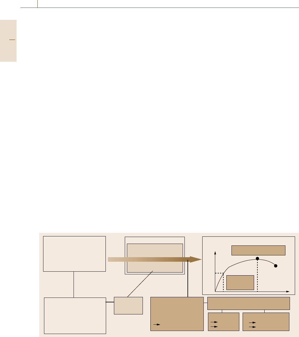
Fig. 1.3 The combination of measurement and testing to determine mechanical characteristics of the technical object
termination of uncertainties in different areas of testing
include
•
Guide for the estimation of measurement uncer-
tainty in testing [1.7]
•
Guide to the evaluation of measurement uncertainty
for quantitative tests results [1.8]
•
Guide for chemistry [1.9]
•
Measurement uncertainty in environmental labora-
tories [1.10]
•
Uncertainties in calibration and testing [1.11].
The methodology of testing combined with mea-
surement is exemplified in Fig. 1.3 for the determination
of mechanical characteristics of a technical object.
Generally speaking, the mechanical properties of
materials characterize the response of a material sample
to loading. The mechanical loading action on ma-
terials in engineering applications can basically be
categorized as tension, compression, bending, shear
or torsion, which may be static or dynamic. In addi-
tion, thermomechanical loading effects can occur. The
testing of mechanical properties consists of measur-
ing the mechanical loading stress (force/cross-sectional
area = F/A) and the corresponding materials response
(strain, elongation) and expressing this as a stress–
strain curve. Its regimes and data points characterize the
mechanical behavior of materials.
Consider for example elasticity, which is an im-
portant characteristic of all components of engineered
structures. The elastic modulus (E) describes the rela-
Part A 1.1
Introduction to Metrology and Testing 1.1 Methodologies of Measurement and Testing 7
tion between a stress (σ) imposed on a material and
the strain (ε) response of the material, or vice versa.
The stimulus takes the form of an applied load, and
the measured effect is the resultant displacement. The
traceability of the stress is established through the use
of a calibrated load cell and by measuring the speci-
men cross-sectional area with a calibrated micrometer,
whereas the traceability of the strain is established
by measuring the change in length of the originally
measured gage length, usually with a calibrated strain
gage. This, however, is not sufficient to ensure re-
peatable results unless a testing reference procedure,
e.g., a standardized tensile test, is used on identi-
cally prepared specimens, backed up by a reference
material.
Figure 1.3 illustrates the metrological and techno-
logical aspects.
•
Metrologically, the measurands of the strength value
are the force (F), area (A), and the length measure-
ment (l) of the technical object, all at a reference
temperature (T).
•
Technologically and concerning testing, the me-
chanical characteristics expressed in a stress–strain
curve depend on at least the following groups of
influencing parameters, to be backed up by appro-
priate references.
– The chemical and physical nature of the ob-
ject: chemical composition, microstructure, and
structure–property relations such as crystallo-
graphic shape-memory effects [1.12]; for exam-
ple, strength values of metals are significantly
influenced by alloying elements, grain size
(fine/coarse), work-hardening treatment, etc.
– The mechanical loading action and dependence
on deformation amplitude: tension, compres-
sion, bending, shear, and torsion; for example,
tensile strength is different from shear strength
for a given material.
– The time dependence of the loading mode forces
(static, dynamic, impact, stochastic) and devi-
ations from simple linear-elastic deformation
(anelastic, viscoelastic or micro-viscoplastic de-
formation). Generally, the dynamic strength of
a material is different from its static strength.
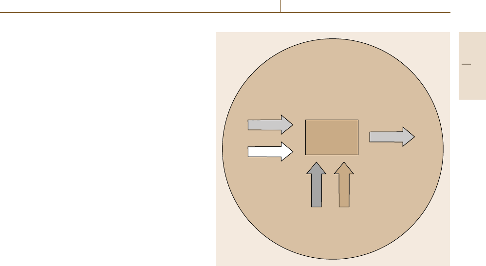
The combined measurement and testing methodolo-
gies, their operating parameters, and the traceability
requirements are illustrated in a highly simplified
scheme by the confidence ring [1.13] shown in Fig. 1.4.
Traceable input
e.g. load
Traceable response
e.g. displacement
Procedural
aspects
e.g. alignment
Reference temperature
Traceable material
characterization
e.g. scale (grain size),
quality (porosity)
Material
response
= Property
The confidence
ring
Fig. 1.4 Confidence ring for material property combined measure-
ment and testing – note that separate traceability requirements apply
to applied stimulus (load), response (displacement), and material
characterization (grain size, porosity)
The confidence ring illustrates that, in measurement
and testing, it is generally essential to establish reliable
traceability for the applied stimulus and the resulting
measured effect as well as for the measurements of
any other quantities that may influence the final result.
The final result may also be affected by the measure-
ment procedure, by temperature, and by the state of
the sample. It is important to understand that vari-
ation in measured results will often reflect material
inhomogeneity as well as uncertainties associated with
the test method or operator variability. All uncertain-
ties should be taken into account in an uncertainty
budget.
1.1.3 Conformity Assessment
and Accreditation
In today’s global market and world trade there is an
increased need for conformity assessment to ensure
that products and equipment meet specifications. The
basis for conformity assessment are measurements to-
gether with methods of calibration, testing, inspection,
and certification. The goal of conformity assessment
Part A 1.1