Cold and Hot Forging: Fundamentals and Applications / Edited by Taylan Altan, Gracious Ngaile, Gangshu Shen
Подождите немного. Документ загружается.

CHAPTER 23
Near-Net Shape
Forging and New Developments
Manas Shirgaokar
Gracious Ngaile
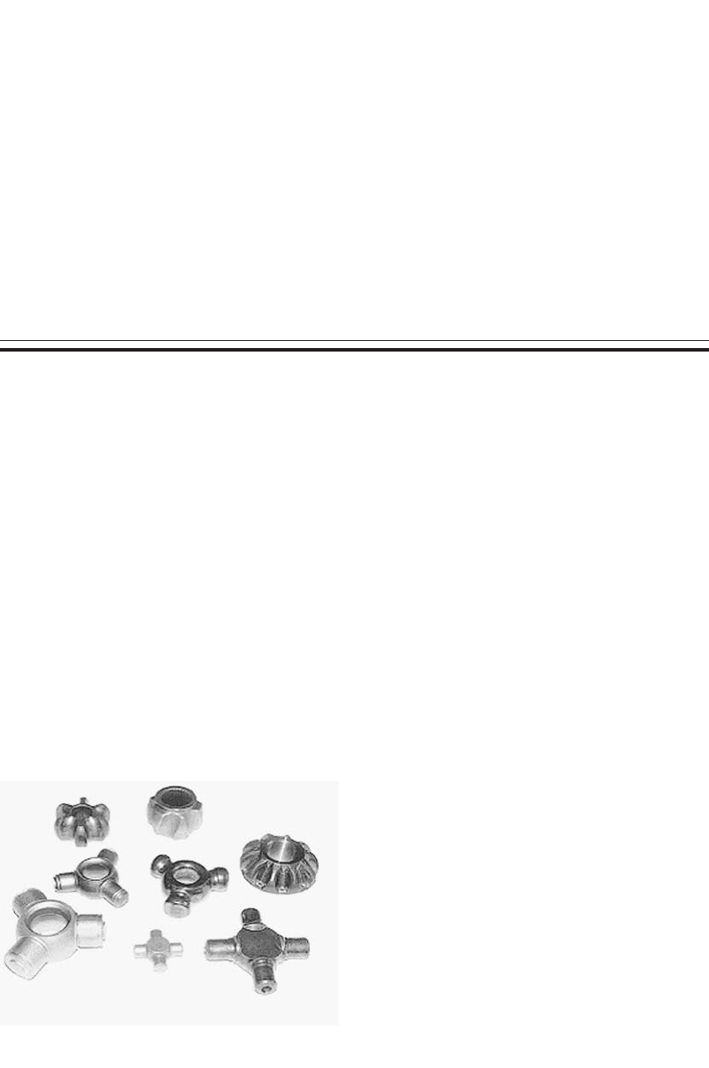
Fig. 23.1
Examples of net shape forged parts [Meidert et al.,
2000]
23.1 Introduction
Net and near-net shape forging companies
generally produce for the automotive industry.
These components are characterized by close di-
mensional tolerances, minimal draft, and the ab-
sence of flash during forging, with minimal or
no postforging machining. This is a major ad-
vantage when machining costs are taken into
consideration. Net shape forging can be defined
as the process of forging components to final
dimensions with no postforging machining nec-
essary. Near-net shape forged components, on
the other hand, are forged as close as possible to
the final dimensions of the desired part, with lit-
tle machining or only grinding after forging and
heat treatment.
The possibility of eliminating the high costs
of machining, combined with the inherent ad-
vantages of cold forging regarding material
strength and finish, make near-net forging very
attractive to the automotive industry.
Examples of typical near-net shape parts are
given in Fig. 23.1. These parts are characterized
by complex geometries and very close toler-
ances, in the range of 0.0004 to 0.002 in. (0.01
to 0.05 mm), at complicated and functionally
important surfaces. The steering spider seen in
the forefront in Fig. 23.1 is a typical net shape
part. The other forgings require minor machin-
ing or grinding. However, functional areas, such
as the gear tooth geometry of the bevel gear, are
ready for assembly [Meidert et al., 2000].
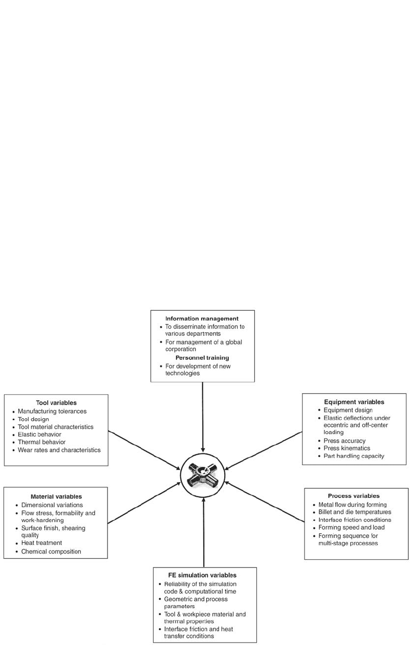
Some of the parameters affecting the quality
of near-net shape forged components are illus-
trated in Fig. 23.2.
23.2 Tolerances in Precision Forging
To reduce cost, it is often desirable to replace
conventional forging that requires several sub-
sequent machining and finishing operations with
precision forging, i.e., cold and warm forging,
which yields parts with good dimensional tol-
erances.
The current minimum dimensional error in
practical cold forging is Ⳳ20 to 50 lm, while
the error in machining has been reduced over the
years to less than Ⳳ1 lm. For cold forging pro-
cesses to compete with machining, the dimen-
Cold and Hot Forging Fundamentals and Applications
Taylan Altan, Gracious Ngaile, Gangshu Shen, editors, p319-335
DOI:10.1361/chff2005p319
Copyright © 2005 ASM International®
All rights reserved.
www.asminternational.org
320 / Cold and Hot Forging: Fundamentals and Applications
Fig. 23.2 Factors influencing the quality of near-net shape forged components. FE, finite element [Meidert et al., 2000]
sional accuracy would have to be increased to
within Ⳳ10 lm. Some of the causes of dimen-
sional variation in precision forging are [Osak-
ada, 1999]:
●
Die manufacturing: The dimensional accu-
racy of the dies directly influences that of the
parts being produced with them. Hence, die
manufacturing is a very crucial part of the
manufacturing sequence of precision parts.
The use of electrical discharge machining
(EDM) and wire EDM machines in manu-
facturing cold forging dies has considerably
improved the accuracy of forging dies.
●
Elastic deflection of the press and tools:
When the forming load is applied, the press
and the tools undergo elastic deflection, thus
affecting the final tolerances on the part be-
ing forged.
●
Variation of process conditions: In practical
situations, process variables such as forming
pressure, lubrication conditions, billet di-
mensions, and material properties do not re-
main constant. These fluctuations affect the
dimensional accuracy of the forming pro-
cess. The billet dimensions and material
properties (flow stress) can be controlled by
involving the suppliers in the design process
to ensure procurement of billets with consis-
tent dimensions and flow stress. The varia-
tion in lubrication conditions can be reduced
by using lubricants with consistent friction
coefficients.
23.2.1 Precision Die Manufacturing
Electrical Discharge Machining. In preci-
sion forging, cemented carbide is the die mate-
rial of choice, rather than high-speed steel, be-
cause of its high stiffness, low thermal effect,
and high wear resistance. A flow chart for manu-
facturing precision dies is shown in Fig. 23.3
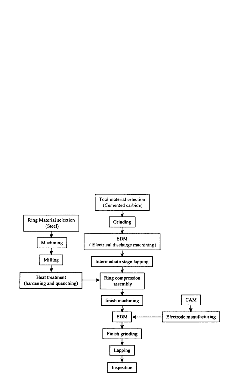
Near-Net Shape Forging and New Developments / 321
Fig. 23.3
Flow chart of die manufacturing by electrical discharge machining (EDM). CAM, computer-aided manufacturing [Yosh-
imura et al., 1997]
[Yoshimura et al., 1997]. The die insert impres-
sion is first made by rough grinding, followed
by electrical discharge die sinking. The com-
pression ring is produced by machining and
milling, followed by hardening or quenching to
increase its stiffness. The die insert is then
shrink-fitted into the compression ring, and the
assembled ring is machined for finishing. The
die insert impression is made by die sinking us-
ing a master electrode, followed by lapping to
obtain a mirrored finish.
Surface coating is done to increase surface
hardness on the working portion of the tools, so
as to reduce wear and damage in that area. Crack
initiation is delayed due to the hardness of the
coating, which prevents any lubricant or work-
piece material from getting wedged in these
cracks. Two commonly used methods of surface
coating are [Yoshimura et al., 1997]:
●
Chemical vapor deposition: TiC, TiCN, TiN,
Al
2
O
3
●
Physical vapor deposition: TiN
23.2.2 Die Deflection in
Net Shape Forging
The stages of process planning, tool design,
and manufacture in net shape forming require
not only the use of a highly qualified engineer
and sophisticated computer-aided design/com-
puter-aided manufacturing (CAD/CAM) pack-
ages but also strict control on the tool and press
settings. Process design in precision forging usu-
ally requires extensive trials before the optimum
settings can be identified to yield the desired part
tolerances. Thus, it is possible to compensate for
the errors in the dimensions by evaluating the
various factors affecting the part tolerances.
Some of the phenomena affecting die deflection/
deformation are listed below in the order that
reflects the increasing dependence on production
run-time [Kocanda et al., 1996]:
●
Elastic deflection is a reversible change in
dimension brought about by the applied
load. It can be controlled by appropriate cal-
culations and design.
322 / Cold and Hot Forging: Fundamentals and Applications
Fig. 23.4 Various stages and influencing factors of the forging process [Ishinaga, 1996]
●
Plastic deformation is a permanent defor-
mation as a result of an unintended increase
in forming load or stress concentration. This
could be caused by improper tool alignment,
inadequate lubrication, change in initial
properties of the workpiece, etc.
●
Cyclic softening or hardening causes signifi-
cant changes in the stress-strain response of
the tool steel. This phenomenon should not
be ignored when the die geometry has stress
concentration features.
●
Thermal expansion of the tooling is a result
of the heat generation during deformation.
●
Relaxation and creep phenomena consider-
ably decrease the prestresses in the die insert.
●
Change in the modulus of elasticity may be
caused by change in temperature of the tool
steel. Generally, the modulus of elasticity de-
creases with increasing temperature.
●
Cyclic plastic deformation, which occurs
near areas of stress concentration, may result
in initiation of microcracks.
●
Softening of tool steel by unwanted temper-
ing. Tempering is a function of both tem-
perature and time and can occur during cold
deformation processing at temperatures
lower than the tempering temperature chosen
for heat treatment of the tool.
23.2.3 Press Deflection in
Net Shape Forging
Major factors that influence the part toler-
ances are the tool and machine deflections and
the various process parameters, such as material
properties, lubrication, temperatures, etc. While
the process parameters and tool design have
been the subject of extensive research, the influ-
ence of press deflection on the accuracy of the
formed part and methodologies to compensate
for these errors have yet to be standardized. Fi-
nite-element (FE) simulation has been employed
to calculate the stress and deflection behavior of
press components such as guide layout, press
frame, and the construction of the crosshead
[Doege et al., 1990]. However, the nonlinear
characteristics of the load-deflection behavior
between adjacent components, the clearances in
the guiding system, and asymmetry in press as-
sembly make it difficult to analyze the elastic
behavior of the press. The horizontal offset and
tilting, which occur during multistage forging or
forging of complex parts, have a detrimental ef-
fect on the part tolerances. In order to quantify
the elastic characteristics of the press, it is nec-
essary to measure the load-deflection relation-
ship of the ram under center and off-center load-
ing conditions together with superimposed
horizontal forces.
In one particular study [Balendra et al., 1996],
a three-dimensional (3-D) FE simulation was
conducted to determine the elastic characteris-
tics of a 400 metric ton screw press. The simu-
lation considered the modeling of the press com-
ponents, appropriate definition of the joints, and
the prestressing requirements for assembling the
frame. The forming loads were obtained by con-
ducting a two-dimensional closed-die, plane-
strain, aerofoil forging simulation. This simula-
tion enabled the determination of the horizontal
offset and tilting of the forging dies for various
orientations of the die parting line, and methods
to minimize the component form errors due to
elastic behavior of the press and location and the
elastic behavior of the forging dies.

Near-Net Shape Forging and New Developments / 323
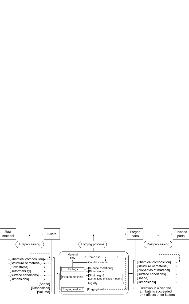
23.2.4 Process Variables in Forging
Figure 23.4 shows the various stages in forg-
ing, with the parameters affecting part attributes
and tolerances [Ishinaga, 1996]. The variable
factors (enclosed in square brackets) affect each
other and cause variations in the dimensions of
the forged part. The entire forging process is di-
vided into three stages:
●
The preprocessing stage addresses the vari-
ables related to the billet. One way to control
the part quality is to ensure minimum devi-
ation in each of the billet factors, such as
dimensions, flow stress, formability, etc.
●
The forging process, which encompasses all
the variables related to the forming process
(temperature, lubrication, etc.), tooling, and
equipment. Variations in the forging pressure
would affect the thickness of the forging due
to elastic deflection of the press and tools.
Off-center loading not only affects the ac-
curacy of the process but is also detrimental
to tool life.
●
The postprocessing stage deals with machin-
ing, surface finishing, or heat treatment of
the forged parts and affects the material
properties, surface conditions, or chemical
composition of the part.
The growing demands for precision cold-
forged products in the automotive industry led
to the development of economical means to
manufacture these parts. Apart from improve-
ments in forging processes, there has been con-
siderable progress in tooling and equipment de-
sign, materials engineering, and lubrication
techniques in order to produce precise compo-
nents. Some of these developments and future
trends are discussed in the subsequent sections.
23.3 Advances in Tool Design
In order to produce precision-forged parts,
factors related to the tooling, namely, elastic de-
flection, eccentricity, thermal expansion, etc.,
have to be considered during the process design
stage. This is especially true in the case of cold
forging, where precision die manufacturing is
necessary to ensure the production of parts to
close tolerances. The following factors have to
be considered in die manufacturing [Yoshimura
et al., 1997]:
●
Proper equipment and process to ensure high
accuracy
●
Proper design of die structure to achieve high
stiffness
●
Proper heat and surface treatments to elimi-
nate the heterogeneity of the die material
●
Proper control of heating conditions to main-
tain constant temperature at the die
Tool life is also a major factor to be consid-
ered while quoting a part. Since the cost of
manufacturing a die is considerable, simultane-
ous process design involving process planning
and die design are essential to ensure that con-
ditions such as loading pressure, stress concen-
tration, etc. remain within the allowable limits
of die performance. Thus, tool wear, tool frac-
ture, and process failure have to be considered
for cost reduction.
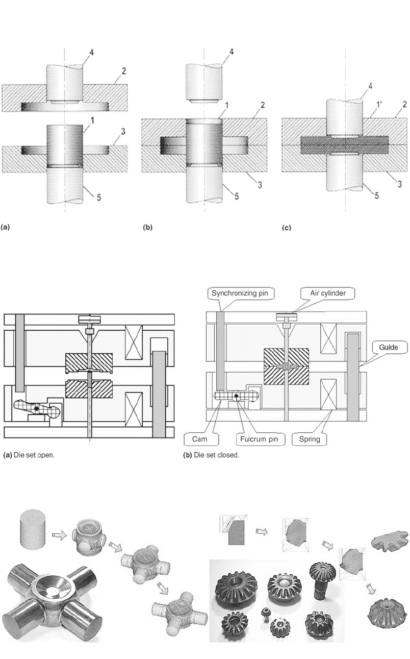
23.3.1 Enclosed- or Trapped-Die Forging
Enclosed-die forging uses multiple-action
tooling as punches press the material in a pre-
enclosed die to fill in the die space (Fig. 23.5).
By controlling the motion of rams, metal flow
can be controlled to obtain the optimum defor-
mation. The ram motions for upper and lower
punches can be set as synchronous, asynchro-
nous, or with back pressure to reduce forming
load or to improve the filling of material. Some
of the advantages of enclosed-die forging are:
●
The ability to form complex shapes in one
process
●
Elimination of flash, thus resulting in mate-
rial savings. Since parts are formed to close
dimensional tolerances, subsequent machin-
ing operations are either reduced or, in some
cases, eliminated.
●
Low forming load is available where the area
penetrated by the punch is relatively small.
A Japanese tool supplier has recently devel-
oped a special die set for forging radially ex-
truded parts and a family of bevel gears (Fig.
23.6 and 23.7) [Yamanaka et al., 2002]. The ad-
vantages obtained from this die set were high
productivity, easy installation in nearly all
presses, the requirement of only compressed air,
and low initial cost.
A similar concept in die design, developed
earlier, incorporates a pantograph, as shown in
the schematic in Fig. 23.8 [Yoshimura et al.,
1997 and 2000]. Hydraulic pressure generated
by an external hydraulic unit and an accumulator
is used for closing the upper and lower die to
form the die cavity. The die-closing pressure is
adjustable. However, if this pressure is too low,
324 / Cold and Hot Forging: Fundamentals and Applications
Fig. 23.5
Enclosed-die forging. 1, billet; 2, upper die; 3, lower die; 4, upper punch; 5, lower punch; 1⬘, finished part [Oudot et al.,
2001]
Fig. 23.6 Enclosed forging die set developed by Yamanaka Engineering [Yamanaka et al., 2002]
Fig. 23.7 Some example parts forged in an enclosed forging die set [Yamanaka et al., 2002]
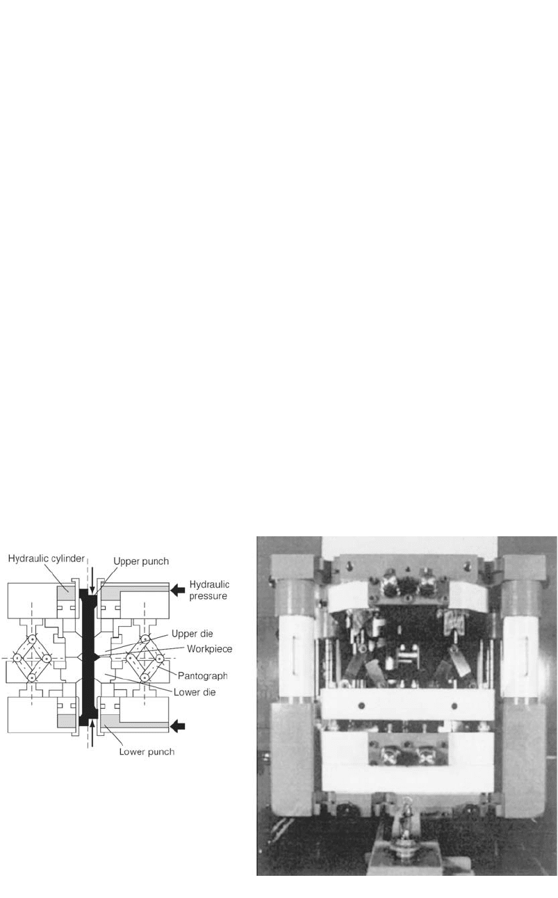
Near-Net Shape Forging and New Developments / 325
Fig. 23.8 Die set for enclosed-die forging developed by Nichidai Corp. [Yoshimura et al., 1997]
it could result in flash formation in the die gap
and cause chipping in the die. The die cavity,
composed of the upper and lower dies, moves at
half the punch speed by the pantograph mecha-
nism in order to obtain uniform deformation of
the material in the axial direction [Yoshimura et
al., 2000]. Similar die designs have been devel-
oped at Institut fu¨r Unformtechnik (Institute for
Metal Forming Technology) at the University of
Stuttgart as well as by European die and press
makers [Siegert et al., 2003].
23.3.2 Innovations in Compressive
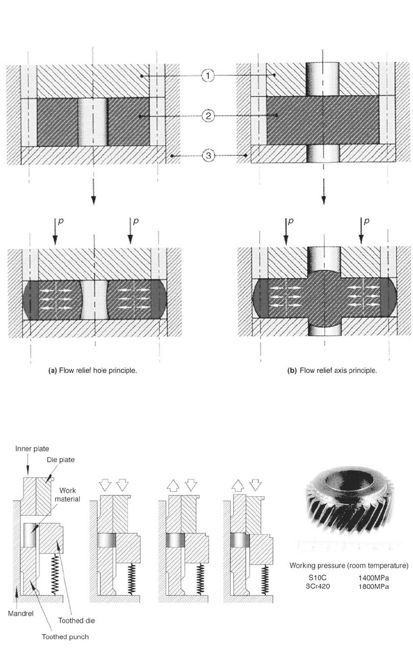
Prestressing of Die Inserts
An important factor in enhancing die life is
the design of compressive prestressing container
systems, which house the die inserts. The con-
ventional prestressing container normally con-
sists of single or double stress rings. Depending
on the complexity of the part and the required
tolerances, the compressive prestress generated
may be too low. STRECON Technology has de-
veloped strip-wound radially prestressed con-
tainers with strength that is 2 to 3 times that of
conventional stress rings [Groenbaek et al.,
1997]. The high strength makes it possible to
provide an optimum prestress for the die, lead-
ing to two- to tenfold improvement in the die
life (Fig. 23.9a). Sometimes, in cold forging
dies, fracture may occur because the conven-
tional radial prestressing does not have any ap-
preciable effect on the stress condition in the
axial direction. To counteract this effect,
STRECON has developed strip-wound contain-
ers with integrated axial prestressing (Fig.
23.9b) [Groenbaek et al., 1997].
The strip-wound containers are manufactured
by winding a thin strip of high-strength steel
around a core of tool steel or tungsten carbide.
During the winding process, the steel strip is pre-
loaded with a controlled winding tension. The
core material has a structure and a hardness that
can withstand high prestress and cyclic working
load. The strip steel is developed especially for
optimum combination of the physical and me-
chanical properties. Optimum stress distribution
is obtained by varying the winding tensions
from layer to layer. The prestressed condition in
the coiled strip is equal to that of a conventional
construction with ‘several hundred’ stress rings.
Consequently, the strip-wound containers can be
loaded with a higher internal pressure than a
conventional multiple stress ring set before the
material will deform plastically. Thus, it is pos-
sible to obtain a higher interference when fitting
a die into a strip-wound container than into a
conventional multiple stress ring set.
326 / Cold and Hot Forging: Fundamentals and Applications
Fig. 23.9 Prestressed strip-wound containers developed by STRECON Technology [Groenbaek et al., 1997 and 2000]
23.3.3 Reduction of Forging
Pressure by Divided Flow Method
To reduce forging load and tool stresses,
Kondo et al. have developed the divided flow
method and applied this concept in forging a va-
riety of parts, such as the gear parts shown in
Fig. 23.10. There are two principles of flow re-
lief shown in Fig. 23.10(a) and (b), namely, flow
relief hole and flow relief axis. In the former, a
blank with a relief hole is compressed by flat
tools, resulting in a centripetal flow as an out-
come of the hole shrinkage, thus creating di-
vided flow. In the relief axis principle, a reduc-
tion in working pressure occurs due to two
reasons: extrusion of the axis serves as flow re-
lief and suppresses the increase in fractional re-
duction in area, and the formation of a friction
hill is prevented due to the divided flow. Re-
search shows that the relief hole principle is
more suitable for working pressure reduction,
since the resistance to flow increases gradually
during forming.
Manufacture of a helical gear utilizing flow
relief axis with back-up pressure is shown in Fig.
23.11 [Kondo, 1999 and 2002]. The forming
process was completed in one step, because the
inner plate moved down with the die plate until
the preset backup load. The final part with the
boss is also shown in Fig. 23.11.
23.4 Advances in Forging Machines
Net shape forging of complex parts, such as
helical gears, helical-tooth pinions, etc., requires
new concepts in press and tooling design, with
consideration of a multitude of interacting vari-
ables such as those shown in Fig. 23.12. In order
to increase the accuracy of the product and to
extend the service life of the tools, press builders
have developed multislide and multiaction hy-
draulic presses [Nakano, 1997, and Ishinaga,
1996].
23.4.1 Multislide Forging Press
Aida Engineering Co. has developed a mul-
tislide forging press for the purpose of minimiz-
ing the effect of off-center loading during mul-
tiprocess transfer forming. The features of this
press are [Nakano, 1997]:
●
Multislide construction: Each slide has its
own independent slide.
●
Time difference operation: Each slide
strokes with a phase difference.
In model MF-7500, three independent slides
operate with a phase difference of 30⬚ and a ca-
pacity per slide of 280 tonf (2500 kN). The total
capacity is 845 tonf (7500 kN) with different
working timing. A schematic of the press with
the slide and die area is shown in Fig. 23.13(a),
Near-Net Shape Forging and New Developments / 327
Fig. 23.10 Gear forging process utilizing divided flow [Kondo, 1999]
Fig. 23.11 One-step divided flow method with back-up pressure [Kondo, 1999 and 2002]
328 / Cold and Hot Forging: Fundamentals and Applications
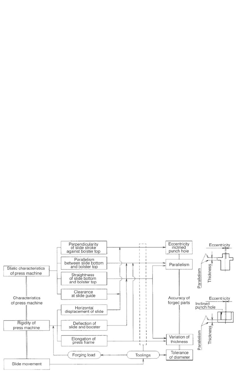
Fig. 23.12 Characteristics of press and accuracy of formed products [Nakano, 1997, and Ishinaga, 1996]
whereas Fig. 23.13(b) shows the slide motion.
As a result of these features it was possible to:
●
Reduce the press capacity and reduce facility
cost due to reduction of total load and torque
of the press
●
Reduce slide tilting and thus improve the ac-
curacy of the formed parts, since the slides
perform independently without any mutual
interference
●
Reduce the vibration and noise during press
operation
Figure 23.14 shows a helical gear cup formed
using the MF-7500 press system [Nakano,
1997]. These cups require a higher forming load
in the first and second stage and hence are ideal
candidates for production in using this press.
The cup, which traditionally required five form-
ing stages, is formed in just three steps. Addi-
tionally, two annealing processes and phosphate
coating were eliminated.
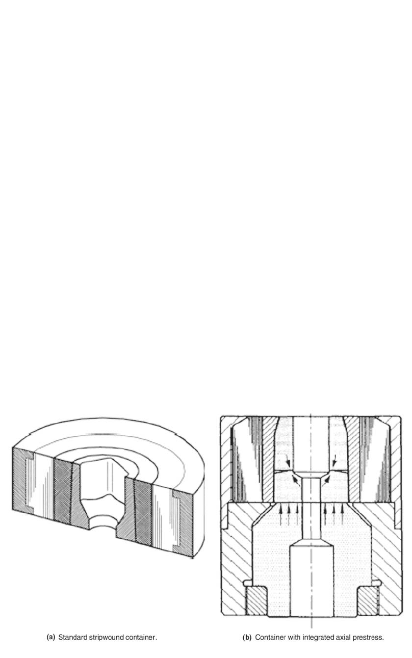
23.4.2 Multiaction Forging Press
Multiaction forging is an effective means of
net shape forging parts with complex features.
In multiaction forming, there is more than one
pressure source to operate the dies and the slide.
Also, the dies make several relative motions dur-
ing one stroke. A multiaction press for forming
helical gears is shown in Fig. 23.15(a). This hy-
draulically operated press has five cylinders: one
for driving the slide, two cylinders in the slide,
and two in the bed. Figure 23.15(b) shows the
construction of a die for forming the helical gear
seen in Fig. 23.15(c) [Nakano, 1997].
23.4.3 Servomotor Press
Figure 23.16 shows a servomotor press that
combines a newly developed large-sized, high-
torque servomotor drive with a crank mecha-
nism. The press uses computer numerical con-
trols for high functionality. It is thus possible to
program the forming motion and speed in order
to set the optimum parameters required to form
the part (Fig. 23.17). This can be used advan-
tageously to increase die life and produce hard-
to-form materials. The press achieves reduced
power usage by using a capacitor to store energy
(Fig. 23.16).
23.5 Innovative Forging Processes
Besides the conventional precision-forging
processes, which are commonly used in the in-
dustry, new processes such as microforming and
orbital forging are being further developed for
practical and economical applications.