Cold and Hot Forging: Fundamentals and Applications / Edited by Taylan Altan, Gracious Ngaile, Gangshu Shen
Подождите немного. Документ загружается.

298 / Cold and Hot Forging: Fundamentals and Applications
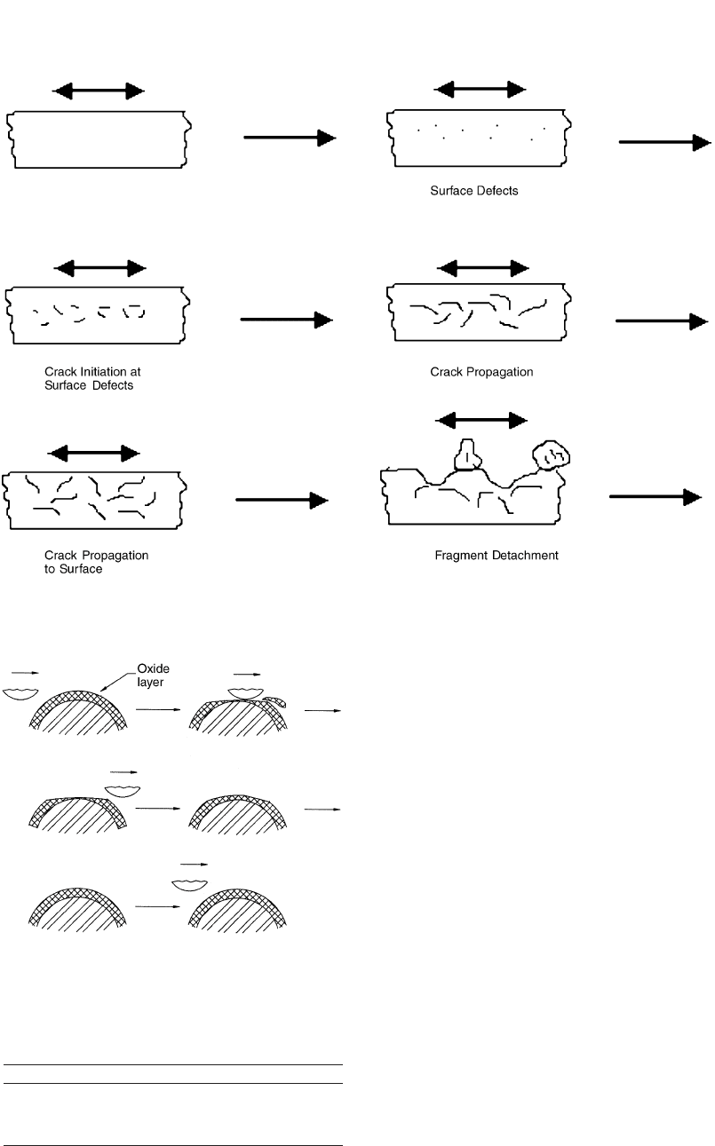
Fig. 22.4 Fatigue wear mechanism [Bay, 2002]
Fig. 22.5 Corrosive wear mechanism [Bay, 2002]
Table 22.1 Summary of wear coefficient, K
adh
,
for adhesive wear [Bay, 2002]
Surface condition Like metallic pairs Unlike metallic pairs
Clean 5 ⳯ 10
ⳮ3
2 ⳯ 10
ⳮ4
Poor lubrication 2 ⳯ 10
ⳮ4
2 ⳯ 10
ⳮ4
Average lubrication 2 ⳯ 10
ⳮ5
2 ⳯ 10
ⳮ5
Excellent lubrication 2 ⳯ 10
ⳮ6
to 10
ⳮ7
2 ⳯ 10
ⳮ6
to 10
ⳮ7
Billet Geometry. The geometry of the billet
influences the amount of sliding that will take
place during the forging process. Because abra-
sive and adhesive wear are proportional to slid-
ing length, the use of preforms where die wear
is a concern will increase die life. A billet or
preform that requires a small amount of defor-
mation can be forged with a lower load (pres-
sure) and a shorter contact time. In large-volume
production, most of the forging deformation is
completed in preform or blocker dies. Thus,
there is little metal flow in the finisher die, which
is used for coining in order to reduce the die
wear and maintain part tolerances [Dahl et al.,
1998, and Schey, 1983].
Billet Weight and Weight Tolerances. Die
wear increases with increasing billet weight.
This is likely the effect of increased interface
pressure and contact time. In addition, if the bil-
let weight exceeds the weight tolerances (i.e.,
the volume of the billet is larger than the volume
of the die cavity), the die will fill prematurely,
causing increased interface pressures and thus
increased wear and decreased fatigue life [Dahl
et al., 1998].
Die Failures in Cold and Hot Forging / 299
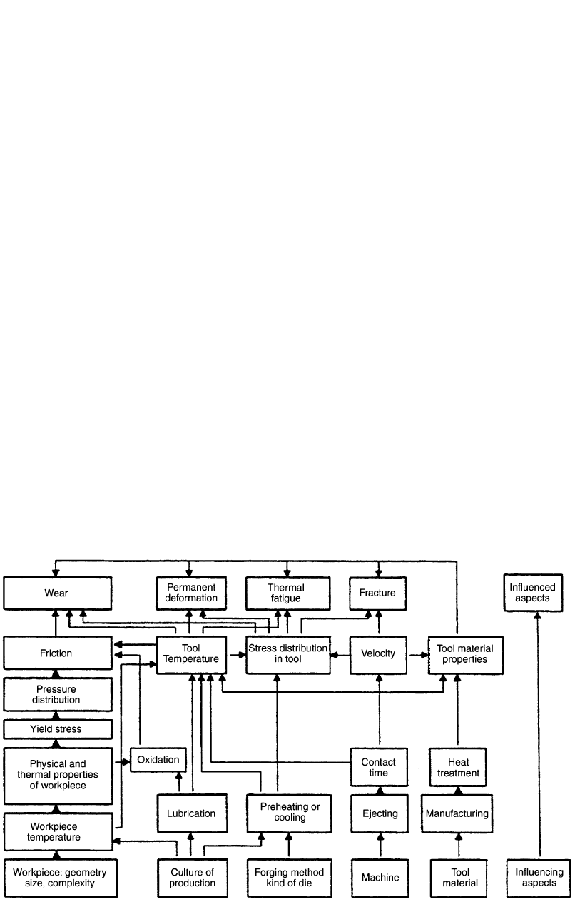
Fig. 22.6 Process parameters leading to die failure [Artinger, 1992]
22.6.2 Billet Separation
Separation Method. The separation method
influences the obtainable weight tolerances. The
effect of exceeding the weight (volume) toler-
ance was discussed previously. In general, crop-
ping and sawing are the primary methods by
which billets are separated. Cropping is known
to produce a geometrically inferior billet to saw-
ing. This method results in more surface and
edge defects (i.e., cracks and burrs) than sawing
[Dahl et al., 1998].
Sorting of billets either by weight or size can
help to extend the useful life of the dies. Billets
can be sorted into two or more groups based on
weight or size. The smaller billets should be
forged first. As the dies begin to wear and the
cavities become larger, larger billets may be in-
troduced. The largest billets are forged at the end
of the die life when the cavity is the largest. This
technique helps to reduce the risk of excessive
interface pressures generated as a result of pre-
mature die fill [Dahl et al., 1998].
Edge Quality. Angularity and other geomet-
rical imperfections that result from billet sepa-
ration can cause uneven loading of the dies. If
the imperfections are consistent in the billet sep-
aration process, the uneven loading becomes a
repeated problem occurring at every stroke of
the press. This may cause high local wear [Dahl
et al., 1998].
22.6.3 Billet Heating
The billet heating process must be closely
controlled in order to keep the billets in the op-
timum forging temperature range and to reduce
scale formation. As discussed previously, hard,
abrasive scale can be a major source of die wear.
Scale may accumulate on the billet surface as a
result of burning during the heating process and
excessive transportation times between heating
and forging. Coatings may be applied to the bil-
lets before heating in order to reduce scale for-
mation [Dahl et al., 1998].
22.6.4 Forging Equipment
The press or hammer type influences the
length of the contact time. Increased contact
times result in increased wear. The reason for
this is that the longer the die is in contact with
the hot billet, the more the temperature of the
dies increases and the temperature of the billet
decreases. The increased die temperatures cause
decreased die hardness due to thermal softening.
Therefore, abrasive wear increases. In addition,
the decreased billet temperatures cause in-
creased flow stress, which leads to increased in-
terface pressures. This also leads to increased
wear. If the die experiences large temperature
oscillations due to long contact times and sub-
300 / Cold and Hot Forging: Fundamentals and Applications
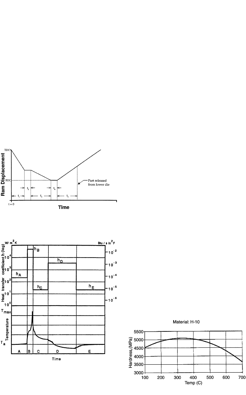
Fig. 22.8
Heat-transfer coefficient and temperature changes
in a typical hot forging operation (A, heated billet
resting on lower die; B, contact time under pressure; C, forging
removed from lower die; D, lubrication of die; E, dwell time with
no billet on lower die before next cycle begins) [Knoerr et al.,
1989]
Fig. 22.7
Contact time components in forging processes
[Dahl et al., 1998]
sequent lubrication/cooling, thermal fatigue
wear may also be a concern [Dahl et al., 1998,
and Schey, 1983].
In general, hydraulic presses transfer energy
from the ram to the workpiece and die slower
than other press types. Thus, the contact time is
longer. Hammers typically transfer energy very
quickly. Thus, the contact time is shorter; how-
ever, fatigue fracture is a major concern for dies
with low toughness. In addition, the stiffness of
the press influences the contact time. If a press
has low stiffness, there is more elastic deflection
during loading. As a result, the contact time is
longer [Kesavapandian et al., 2001].
The press (ram) speed influences the relative
sliding velocity between the billet and the dies.
Increased sliding velocity results in increased
strain rates, which cause increased flow stress
and thus increased wear and decreased fatigue
life. However, if the press speed it too slow, long
contact times may become important [Dahl et
al., 1998].
The effect of the press (ram) speed and the
contact time is extremely important for die life.
The longer the contact time between the billet
and the dies, especially under pressure, the
shorter is the die life. It is useful to divide the
total contact time, t
T
, in precision forging into
its various components, as follows (using forg-
ing in a vertical press as an example) (Fig. 22.7)
[Dahl et al., 1998]:
t ⳱ t Ⳮ t Ⳮ t Ⳮ t Ⳮ t (Eq 22.2)
T12345
where:
●
t
1
⳱ rest time. (The heated billet or preform
is placed on the lower die. The pressure at
the die/workpiece interface is due to the
workpiece weight only.)
●
t
2
⳱ initial dwell time under pressure. (The
upper die touches the workpiece. The ram
stops for a very short time while the pressure
builds up. This is the case in some hydraulic
presses, or when a mechanical press ram has
some excessive clearances in the eccentric
bearings, or the lift-up cylinders are not
functioning properly.)
●
t
3
⳱ contact time under pressure. (Defor-
mation occurs during this time. This time is
influenced by the press stiffness. The effect
of elastic deflection, i.e., press stiffness, is
especially important in mechanical and
screw presses.)
●
t
4
⳱ final dwell time under pressure. (The
forging stroke is completed. The ram is at
bottom dead center (BDC). The ram must be
lifted upward. This dwell time is due to elas-
tic deflection of the press in mechanical and
Fig. 22.9 Temperature-hardness curve [Dahl et al., 1999]
Die Failures in Cold and Hot Forging / 301
screw presses and the time necessary to re-
verse the hydraulic pressure to lift up the ram
in some hydraulic presses.)
●
t
5
⳱ final dwell time without pressure. (The
upper ram has lifted, but the forging is still
in the die before it is removed manually or
lifted out by a knockout mechanism.)
As shown in Fig. 22.8, the heat-transfer co-
efficient at the die/workpiece interface is differ-
ent for the different contact time components.
22.6.5 Forging Dies
Die Material and Heat Treatment. The
strength (i.e., flow stress), toughness, resistance
to thermal softening, and hot hardness of the hot
forging die material influence its wear resis-
tance. Recall that abrasive and adhesive wear are
inversely proportional to the strength/hot hard-
ness of the die material. In addition, good tough-
ness is also important for resistance to fatigue
wear/fatigue fracture. Because toughness is a
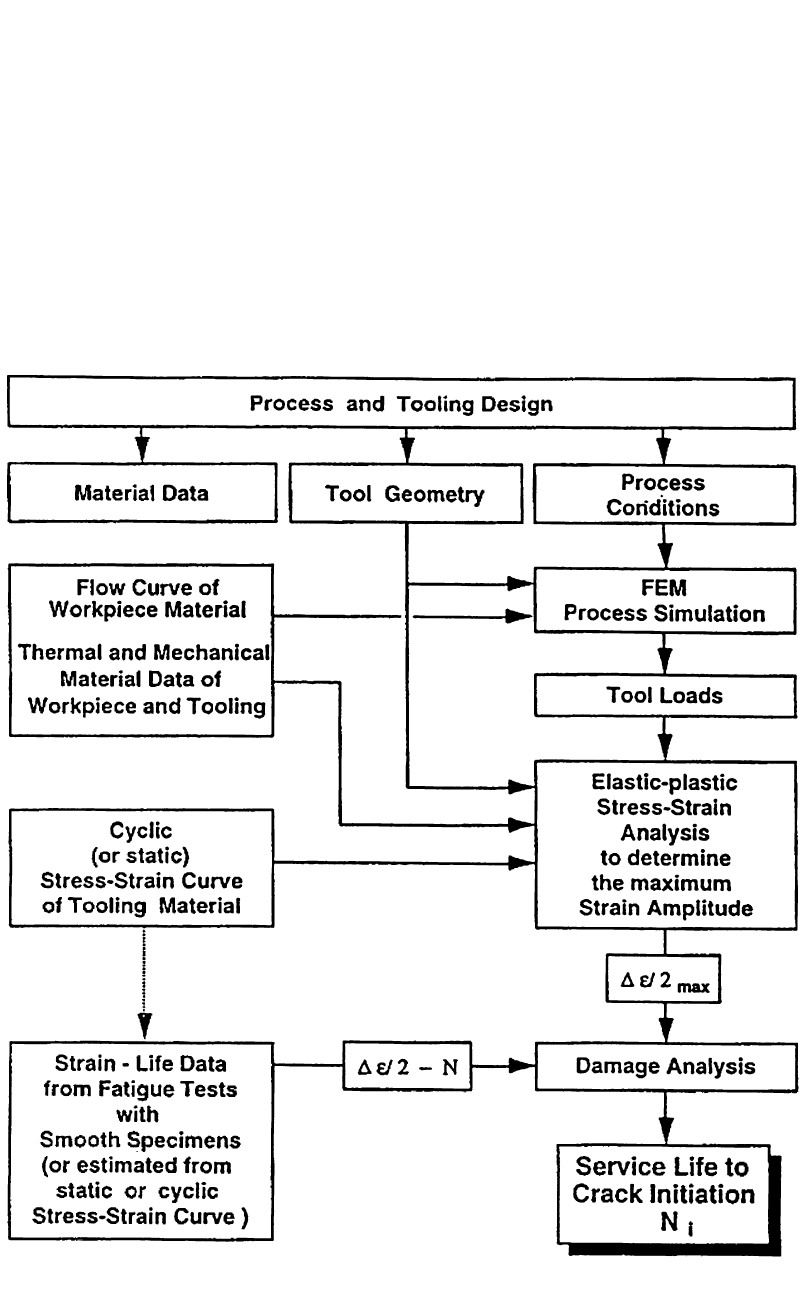
Fig. 22.10 Fatigue analysis method [Knoerr et al., 1994]
302 / Cold and Hot Forging: Fundamentals and Applications
function of strength and ductility, it usually in-
creases with increasing temperature [Altan et al.,
1983, and Dahl et al., 1998]. A typical tempera-
ture-hardness curve is shown in Fig. 22.9. Ad-
ditional information on die materials is given in
Chapter 21, “Die Materials and Die Manufac-
turing,” in this book.
Alloying elements such as chromium, tung-
sten, vanadium, and molybdenum are typically
employed in hot forging dies in order to improve
the wear resistance of the die. In particular, mo-
lybdenum is responsible for resistance to ther-
mal softening at hot forging temperatures. Va-
nadium improves the resistance to abrasion and
thermal fatigue. Tungsten increases toughness
(resistance to mechanical fatigue) and resistance
to thermal softening [Dahl et al., 1998, and Tul-
syan et al., 1993].
In addition, the microstructure resulting from
heat treatment influences die wear. It has been
shown that microstructure type, grain size, uni-
formity, and the number of microcracks affect
die wear [Shivpuri et al., 1988].
The thermal properties of the die material also
influence its wear resistance. High thermal con-
ductivities eliminate the large thermal gradients
that lead to thermal fatigue wear by carrying the
Fig. 22.11
Fatigue fracture in forward extrusion die [Lange
et al., 1992a]
Fig. 22.12 Forward extrusion die cross section used by Hettig for fatigue failure investigation [Hettig, 1990]
Table 22.2 Test conditions and results of Hettig’s fatigue failure investigation along with fatigue
analysis results [Knoerr et al., 1994]
Transition
radius (R)
Case Insert material Hardness, HRC
Die opening angle (2␣),
degrees in. mm
Experimental die life,
parts
Predicted die life,
parts
I AISI M2 61 120 0.04 1 50–400 280
II AISI D2 60 120 0.04 1 65–200 210
III AISI D2 60 90 0.04 1 900–1000 950
IV AISI D2 60 90 0.10 2.5 10,000–11,000 10,500
Die Failures in Cold and Hot Forging / 303
heat away from the die surface more quickly.
Low thermal expansion rates reduce stresses in-
duced by dimensional changes in the die at high
temperatures [Dahl et al., 1998].
Surface Treatments. Because dies simulta-
neously require high hardness to prevent wear
and high toughness to prevent fatigue fracture,
many dies incorporate a surface treatment, such
as nitriding or boriding in hot forging or a coat-
ing such as TiN or TiAlN in cold forging, that
improves the hardness of the surface while leav-
ing the bulk of the die relatively soft [Dahl et
al., 1998].
Die Design. In hot forging, die design param-
eters, such as flash geometry, fillet radii, draft
angles, and die face contact area, influence die
wear and fatigue life. It has been found that die
wear decreases and fatigue life increases with an
increase in flash thickness, because the contact
stresses between the die and the flash decrease.
In addition, die wear increases and fatigue life
decreases with an increase in flash-metal escape,
because higher contact stresses are produced by
the higher loads required to deliver higher flash-
metal escape rates [Aston et al., 1969].
As fillet radii increase, die wear decreases and
fatigue life increases, because small radii intro-
duce stress concentrations. Increasing draft an-
gle decreases die life, because higher draft an-
gles require higher loads to fill the die cavity
[Knoerr et al., 1989].
Die Manufacturing. The method used to
manufacture the die influences the surface char-
acteristics and thus the wear of the die. For ex-
ample, electrical discharge machining typically
produces a very hard and brittle surface that has
been shown to be more wear resistant than those
produced with other manufacturing methods
[Knoerr et al., 1989].
Surface Finish. Generally, the rougher the
surface, the more wear is produced. This results
because the number of asperities in contact is
less for a rough surface. Thus, greater loads per
asperity are generated on rough surfaces. How-
ever, in cases where the surfaces are very smooth
and, more importantly, very clean, adhesive
Fig. 22.13 (a) Plastic zone at the transition radius. (b) Tensile maximum principal stress at transition radius [Knoerr et al., 1994]
Fig. 22.14
Fatigue fracture in backward extrusion of con-
stant velocity joints [Nagoa et al., 1994]
304 / Cold and Hot Forging: Fundamentals and Applications
wear is likely to occur unless coatings are used
[Tulsyan et al., 1993].
22.6.6 Lubrication
Die Lubricant Type. The lubricant type in-
fluences the interface pressure and the heat
transfer between the die and the billet. In gen-
eral, decreasing lubricity results in increased in-
terface pressure and thus increased die wear and
decreased fatigue life. Also, the lubricant acts as
an insulator in order to protect the die against
extreme temperature changes and thermal fa-
tigue wear [Schey, 1983, and Dahl et al., 1998].
Mode of Application. In hot forging, the lu-
bricant application parameters, i.e., spray time,
spray angle, spray distance, and flow rate, influ-
ence how the lubricant covers the die. Inade-
quate lubrication results in increased interface
pressure and reduced insulation against extreme
die-temperature changes. However, excessive
lubricant can result in the buildup of solid lu-
bricant particles in die cavities. This buildup
may cause premature die fill and increased in-
terface pressure [Dahl et al., 1998].
22.6.7 Process Conditions
Die Temperature. The die temperature influ-
ences the hardness of the die. In general, the die
hardness is inversely proportional to the die tem-
perature. Thus, because abrasive and adhesive
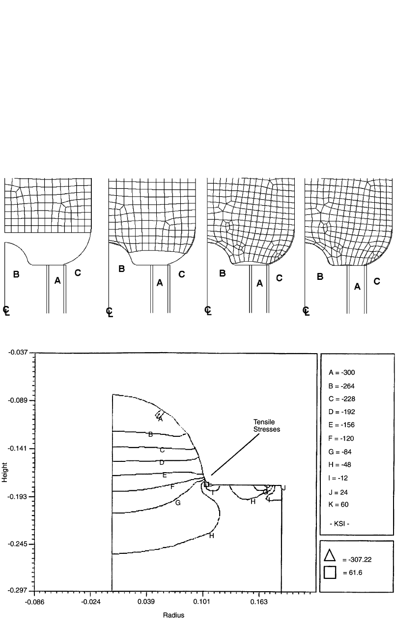
Fig. 22.15 (a) Plastic zone at the cup bottom. (b) Tensile maximum principal stress at cup bottom [Nagao et al., 1994]
Fig. 22.16 (a) Plastic zone at the flange area. (b) Tensile maximum principal stress at flange area [Nagao et al., 1994]
Die Failures in Cold and Hot Forging / 305
die wear are inversely proportional to die hard-
ness, die wear is proportional to die temperature,
which is significantly affected by contact times
[Dahl et al., 1998, and Schey, 1983].
Billet Temperature. The billet temperature
influences the flow stress of the material. As dis-
cussed previously, increased flow stress results
in increased interface pressure and thus in-
creased wear and decreased fatigue life [Dahl et
al., 1998 and Schey, 1983]. In addition, the billet
temperature influences the amount of scale on
the workpiece surface, i.e., the amount of scale
typically increases with increasing temperature
[Tulsyan et al., 1993].
Sliding Velocity. Increasing the sliding ve-
locity between the die and the workpiece in-
creases die wear. In general, the relative sliding
between the die and workpiece creates heat. The
higher the sliding velocity, the more heat is pro-
duced. This heating lowers the hardness of the
die [Tulsyan et al., 1993].
Number of Forging Operations. While the
exact number of forging operations is not im-
portant, what is important is that there are
enough operations so that the severity of the de-
formation at one station is not excessive. Exces-
sive deformation in one die cavity causes large
sliding between the billet and the die, which re-
sults in increased die wear. Therefore, appropri-
ate and economic preforming operations should
Fig. 22.17
Deformation of the inserts under load for the straight container (original design) and the profiled container (optimum
design) [Nagao et al., 1994]
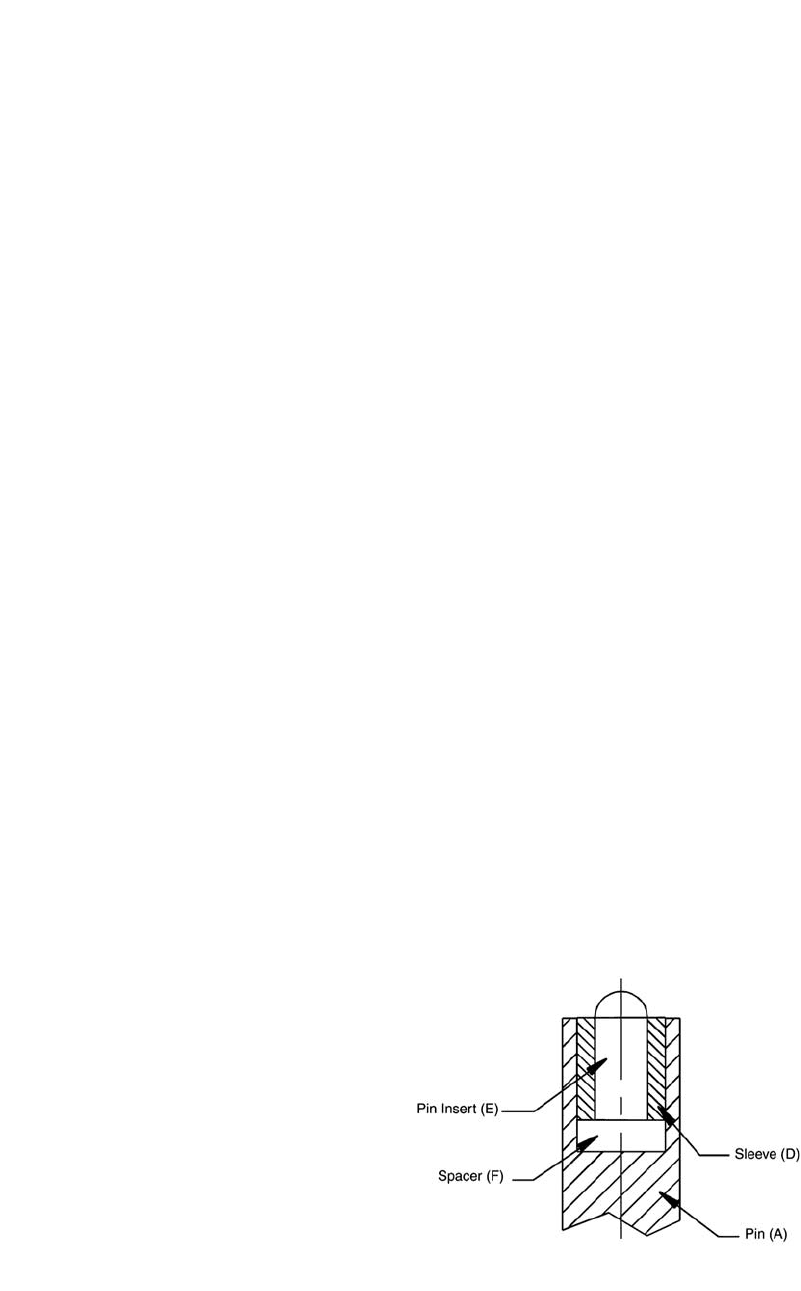
Fig. 22.18
Knockout pin design and insert failure point
[Hannan et al., 2001]
306 / Cold and Hot Forging: Fundamentals and Applications
be used, especially just prior to the final forging
operation where wear rates must be kept low to
maintain desired tolerances [Dahl et al., 1998].
Transfer Time. The transfer time, i.e., amount
of time required to transfer the billet from the
furnace to the press, influences the temperature
of the billet. Cooling of the billet will raise the
flow stress of the billet. As discussed previously,
increased flow stress results in increased inter-
face pressure and thus increased wear and de-
creased fatigue life [Dahl et al., 1998].
Cycle Time/Production Rate. If the heated
billet is allowed to rest on the die for a long
period of time before deformation occurs, the
billet will cool and the die will heat. Thus, wear
will be increased, because the flow stress of the
billet will be increased and the hardness of the
dies will be decreased [Dahl et al., 1998]. Large
production rates in hot forging will increase the
overall temperature of the dies, i.e., in high-
speed horizontal hot forging machines. In such
cases, large amounts of coolants and lubricants
Fig. 22.19 FEM model of knockout pin [Hannan et al., 2001]
Fig. 22.20 Tensile maximum principal stress in failure area [Hannan et al., 2001]
Die Failures in Cold and Hot Forging / 307
are needed in order to reduce die temperatures.
Alternatively, it is also possible to leave one
forging station intermittently empty in order to
provide time for the dies to cool.
In order to produce an economically sound
part with prolonged die life by either cold or hot
forging, a multitude of variables, as discussed
above, must be carefully considered. In partic-
ular, the effect and importance of each variable
based on the nature of the given component must
be assessed.
22.7 Prediction of Die Fatigue
Fracture and Enhancement of
Die Life in Cold Forging Using
Finite-Element Modeling (FEM)
A reliable method to analyze, predict, prevent,
and/or control die fatigue fracture has long been
one of the most important issues in cold forging.
Therefore, a fatigue analysis method that can be
utilized to estimate tool life has been developed
and can be summarized as follows (Fig. 22.10)
[Knoerr et al., 1994, and Matsuda, 2002]:
●
The forging process is simulated using FEM
in order to estimate the tool stresses.
●
The tool stress values are used to complete
an elastic-plastic stress-strain analysis of the
tooling using FEM.
●
The stress-strain analysis is used to perform
a damage analysis and estimate the number
of cycles until fatigue fracture.
If the predicted tool life is insufficient,
changes in the process and tooling design must
be made in order to reduce the loading condi-
tions. A significant increase in tool life can be
achieved by reducing the stresses in the highest
loaded zone below the yield strength of the tool
material. This may be achieved by the following
means [Knoerr et al., 1994]:
●
Change material flow in the die to reduce the
contact stresses on the tool.
●
Redesign the process to avoid drastic
changes in the direction of the material flow,
which usually leads to peaks in the contact
stress.
●
Increase the transition radii to reduce the
notch effect.
●
Split the tooling at the highest loaded zone.
●
Increase the interference of the stress ring.
●
Apply advanced stress ring techniques, such
as strip-wound containers or profiled stress
rings.
Several case studies where this fatigue anal-
ysis method was employed are presented as fol-
lows.
22.7.1 Forward Extrusion—A Case Study
In forward extrusion, fatigue cracks initiate at
the transition radius to the extrusion shoulder
and propagate in the radial direction (Fig.
22.11).
In order to verify the fatigue analysis method
for evaluating tool life, an experimental inves-
tigation of fatigue fracture of forward extrusion
dies, performed at the Institute for Metal Form-
ing (IFUM) at the University of Stuttgart, was
used [Hettig, 1990]. Figure 22.12 shows the
cross section of the forward extrusion die, and
Table 22.2 summarizes the test conditions and
the results obtained. In addition, Table 22.2 sum-
marizes the results obtained from the fatigue
analysis for the same test conditions. As the ta-
ble shows, the predicted die lives were in the
range of those found experimentally. Thus, the
fatigue analysis method was verified.
Table 22.2 illustrates that the die opening an-
gle and the transition radius have a large effect
on the die life. With FEM-based fatigue analy-
sis, this effect is noted quickly and economi-
cally. Also, the FEM-based fatigue analysis eas-
ily determines the location where fatigue
fracture will occur. Figure 22.13 shows the local
plastic zone at the transition radius found during
the FEM-based stress-strain analysis of the die.
Figure 22.13 also shows that the maximum prin-
cipal stresses in this same region are tensile,
Fig. 22.21
Split knockout pin insert design [Hannan et al.,
2001]