Cold and Hot Forging: Fundamentals and Applications / Edited by Taylan Altan, Gracious Ngaile, Gangshu Shen
Подождите немного. Документ загружается.


224 / Cold and Hot Forging: Fundamentals and Applications
Table 17.8 Comparison of measured and predicted punch pressures in backward cup extrusion of
various steels
Measured
pressure Pressure predicted using formula from Table 17.5, ksi (MPa)
Steel Reduction, % ksi MPa P.E.R.A. Pugh James and Kottcamp Schoffmann
1005, hot rolled 50 223 1538 245 (1689) 236 (1627) 214 (1475) 194 (1338)
60 228 1572 248 (1710) 240 (1655) 237 (1634) 213 (1469)
70 249 1717 260 (1793) 249 (1717) 270 (1862) 240 (1655)
8620, subcritical annealed 50 305 2103 389 (2682) 340 (2344) 300 (2068) 307 (2117)
60 309 2130 393 (2710) 345 (2379) 326 (2248) 337 (2324)
70 341 2351 412 (2841) 359 (2475) 366 (2523) 377 (2599)
1038, annealed 50 304 2096 309 (2130) 325 (2241) 309 (2130) 290 (1999)
60 313 2158 312 (2151) 331 (2282) 343 (2365) 319 (2199)
70 327 2255 327 (2255) 344 (2372) 392 (2703) 357 (2461)
1018, hot rolled 50 286 1972 320 (2206) 317 (2186) 290 (1999) 281 (1937)
60 293 2020 323 (2227) 322 (2220) 319 (2199) 308 (2124)
70 313 2158 338 (2330) 335 (2310) 362 (2496) 345 (2379)
12L14, annealed 50 274 1889 303 (2089) 284 (1958) 293 (2020) 245 (1689)
60 282 1944 306 (2110) 288 (1986) 329 (2268) 269 (1855)
70 316 2179 321 (2213) 300 (2068) 380 (2620) 301 (2075)
with both punches was used whenever experi-
mental data were available for both cases.
17.10 Prediction of Extrusion
Loads from Model Test
Except where exaggerated inhomogeneities
are present in the deforming material, metal flow
in extrusion is influenced mainly by tool ge-
ometry and lubrication conditions. The effects
of material properties on metal flow are rela-
tively insignificant [Altan, 1970, and Sashar,
1967].
If a strain-hardening material is considered
and the friction at the tool/material interfaces of
the deformation zone is neglected, the external
mechanical energy is equal to the internal de-
formation energy [Altan, 1970], i.e.:
pAvDt ⳱ ¯rd¯edV (Eq 17.10)
a0
冮
v
or
¯e
h
pV⳱ ¯rd¯e (Eq 17.11)
a
冮
0
where, in addition to the symbols previously de-
fined, p
a
is average punch pressure, V is volume
of deforming material, v is punch velocity, and
Dt is time increment. The left side of Eq 17.10
represents the amount of mechanical energy nec-
essary for deformation. This energy is intro-
duced by the punch, which moves at a velocity
(v) during the time (Dt) necessary to extrude the
volume of material equal to the volume of the
deformation zone (V ⳱ A
0
vDt). The right side
of Eq 17.10 represents the total deformation en-
ergy obtained by adding the deformation ener-
gies consumed within each volume element in
the deformation zone. This total deformation en-
ergy can be calculated only if the flow stress,
and effective strain, at each volume ele-¯r,¯e,
ment are known. Since this information is not
usually available, the following averaging
method can be used.
Assuming that every volume element in the
deformation zone has the same average strain,
and the same average flow stress, then Eq¯e,¯r ,
a
17.11 can be written as:
pV⳱ ¯r ¯e V (Eq 17.12)
aaa
and with Eq 17.12 gives:
n
¯r ⳱ K¯e
nⳭ1
p ⳱ K¯e (Eq 17.13)
aa
or
1/nⳭ1
p
a
¯e ⳱ (Eq 17.14)
a
冢冣
K
Equations 17.13 and 17.14 can be used for
predicting extrusion pressures from a model test.
First, a model material (plasticine, aluminum, or
mild steel) is extruded using certain tool geom-
etry, and the extrusion pressure, p
a
, is measured.
By use of Eq. 17.14 and the known K and n
values of the model material, the average strain,
is calculated. Then, the calculated values of¯e ,
a
and the K and n values of the real material¯e
a
are used with Eq 17.13 to estimate the real ex-
trusion pressure.

Cold and Warm Forging / 225
Table 17.9 Comparison of measured and predicted (model test) punch pressures in backward
extrusion of various steels (model material, hot rolled 1005 steel; ⴔ psi)
0.25
¯r 86,000¯e
K Measured pressure Predicted pressure
Steel ksi MPa n Reduction, % ksi MPa ksi MPa
8620, subcritical annealed 120 827 0.173 50 305 2103 304 2096
60 309 2130 308 2124
70 341 2351 334 2303
1038, annealed 134 924 0.255 50 304 2096 347 2392
60 313 2158 357 2461
70 327 2255 387 2668
1018, hot rolled 117 807 0.244 50 286 1972 300 2068
60 293 2020 305 2103
70 313 2158 335 2310
12L14, annealed 115 793 0.312 50 274 1889 302 2082
60 282 1944 315 2172
70 316 2179 343 2365
Using 1005 hot rolled steel ⳱ 86,000(¯r
psi) as the model material, the model test
0.25
¯e
method described above was applied in order to
predict punch pressures in forward extrusion for
a series of the other steels. A comparison of the
experimental and predicted values is given in
Table 17.9. It can be seen that the largest differ-
ence between the two values does not exceed
20%, while predictions are within 10% for most
extrusions. It should be noted that the extrusion
pressure, p
a
, in Eq 17.13 is the same as the ejec-
tor pressure. The punch pressure is obtained
from the extrusion ratio. For instance, for R ⳱
80%, punch pressure ⳱ p
a
/0.80.
In forward extrusion, only the deformation
pressure, i.e., the end pressure, can be predicted
from a model test. In order to predict the maxi-
mum load, the friction in the extrusion container
must be considered. With the symbols listed in
Fig. 17.10(a), the equilibrium of forces in the
axial direction gives:
2
pD
dp ⳱ dxspD (Eq 17.15)
xf
冢冣
4
Assuming a constant frictional shear stress, s
f
,
at the tool/material interface, s
f
⳱ Eq 17.15f¯r ,
0
transforms into:
dp 4f ¯r
x0
⳱ (Eq 17.16)
dx D
by integrating, Eq 17.16 gives:
4f ¯r
0
p ⳱ x Ⳮ C (Eq 17.17)
x
D
The integration constant C is determined from
the condition for x ⳱ 0, p
x
⳱ p
e
in Eq 17.13,
or, in forward extrusion:
4f ¯r
0
p ⳱ p Ⳮ L (Eq 17.18)
xe
D
Equation 17.18 illustrates that the peak pres-
sure, p
p
, in forward rod extrusion is equal to the
sum of the end pressure, p
e
, necessary for de-
formation and the additional pressure, p
fc
⳱
L/D, necessary to overcome the container4f ¯r
0
friction.
The shear friction factor, f, is to be determined
from Eq 17.18 for a given billet length, L, and
for the known yield stress, of the model ma-¯r ,
0
terial, in this case, 1005HR steel. It is reasonable
to assume that the friction factor, f, would not
significantly change from one steel to another.
The average strain, is determined from Eq¯e,
17.14, using the data for 1005 HR steel. The end
pressure, p
e
, is then determined from Eq 17.13.
Finally, the peak pressures, p
p
, are calculated for
different steels using Eq 17.18. The results are
compared with experimental values in Table
17.10. The agreements between prediction and
experiment are, in most cases, within 10 to 15%
and can be considered acceptable for practical
purposes.
17.11 Tooling for Cold Forging [Lange
et al., 1985, and ICFG, 1992]
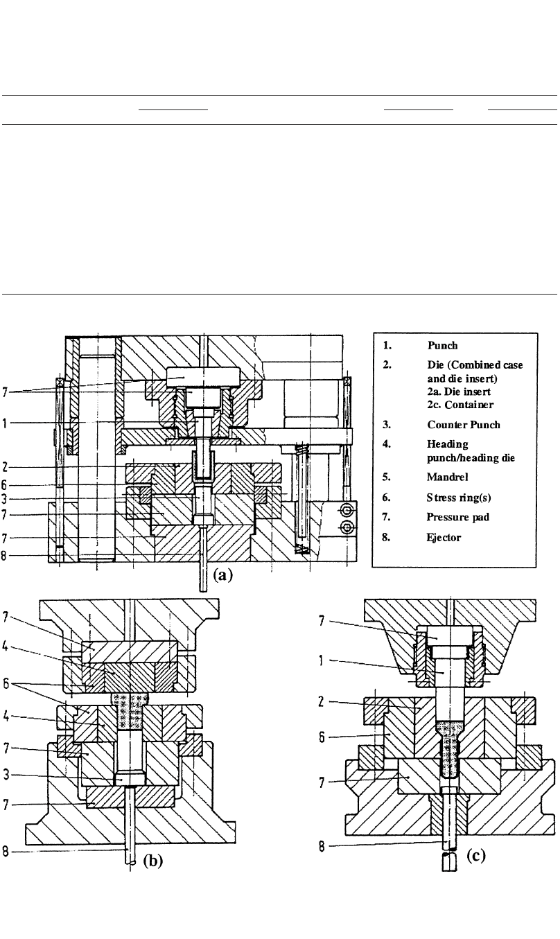
A tooling setup for cold forging is shown in
Fig. 17.14.
17.11.1 Punch
The punch is the portion of the tool that forms
the internal surface of the workpiece in a can
extrusion, or that pushes the workpiece through
a die in a rod, tube, or open-die extrusion.
226 / Cold and Hot Forging: Fundamentals and Applications
Fig. 17.14 Tooling setup for cold forging. (a) Can extrusion. (b) Upsetting. (c) Forward extrusion [ICFG, 1992]
Table 17.10 Comparison of measured and predicted (model test) peak punch pressures in forward
extrusion of various steels
K Measured pressure Predicted pressure
Steel ksi MPa n Reduction, % ksi MPa ksi MPa
1018, hot rolled 117 807 0.224 20 111 765 95 655
50 186 1282 165 1138
60 205 1413 190 1310
12L14, annealed 115 793 0.312 20 86 593 90 621
50 172 1186 158 1089
60 187 1289 192 1324
8620, subcritical annealed 120 827 0.173 20 98 676 100 689
50 178 1227 182 1255
60 205 1413 220 1517
1038, annealed 134 924 0.255 20 103 710 100 689
50 190 1310 180 1241
60 210 1448 220 1517
4340, annealed 167 1151 0.193 20 122 841 132 910
50 228 1572 232 1600
60 251 1731 275 1896

Cold and Warm Forging / 227
In forward rod extrusion, wear of the punch
is normally not a problem. Compressive stresses
range up to 350 ksi (2413 MPa) and sometimes
slightly more. In can extrusion, the punch is sub-
jected to compressive and bending load as well
as heavy wear, which increases the temperature
at the punch nose, especially in high-speed
presses. During stripping, tensile stresses occur.
In ironing, the punch pushes the workpiece
through the die and forms its internal surface.
Depending on size, shape, loading, and wear,
both tool steels and cemented carbides may be
selected as tool materials.
17.11.2 Die, Die Insert, Container, Case
(Combined Case and Die Insert)
The die is the portion of the tool assembly that
contains the workpiece and forms the external
surfaces. The choice of the material depends on
the maximum internal pressure and fatigue as
well as the toughness and wear-resistance re-
quirements.
Normally, dies are reinforced by one or more
stress rings. Depending on the stress state, prin-
cipal designs used in the industry are as follows:
●
Die
●
Die with one-piece insert
●
Die with axially split insert
●
Die with transversely split insert
Depending on size and shape, both tool steels
and cemented carbides may be selected for the
die insert.
17.11.3 Counter Punch
The counter punch forms the base shape and
is usually used to eject the workpiece from the
die. In both can extrusion and coining or sizing,
the counter punch is subjected to compressive
stresses similar to those occurring in punches.
Both tool steels and cemented carbides may be
selected.
17.11.4 Heading Punch/Heading Die
The heading punch upsets the head of the
workpiece. The heading die contains the shank
and forms the underhead surface of the work-
piece. Choice of the tool material and its heat
treatment depends on the compressive stresses
(up to 300 ksi, or 2068 MPa, and more), section
size, and the demand for wear resistance and
toughness. Besides tool steels, for a range of
small and medium section sizes, cemented car-
bides may be used when long runs demand high
wear resistance.
17.11.5 Mandrel (Pilot)
The mandrel or pilot is that part of the punch
assembly that enters a hollow billet and forms
the inside wall. The mandrel is subjected to wear
and high tensile stresses, and therefore, the
choice of material is aimed at properties such as
wear resistance and/or high yield strength. Due
to high tensile stresses, tool steels are normally
used.
17.11.6 Stress Rings
The stress rings form the intermediate and
outer portions of the die assembly to prevent the
die from bursting. The tensile stresses will
amount to 200 ksi (1379 MPa) and more. Nor-
mally, tool steels are used.
17.11.7 Pressure Pads
The pressure pad is the block of material that
supports and spreads the load behind the pad or
die. Sufficient thickness is important in order to
spread the load properly and to avoid bending.
An extreme degree of parallelism and square-
ness is essential. The tool material should pro-
vide high compressive strength up to 220 ksi
(1517 MPa). Normally, tool steels are used.
17.11.8 Ejector
The ejector is the part of the tooling that ejects
the workpiece from the die, usually without tak-
ing part in the forming operation. The choice of
the material depends on the section used and the
ejection pressure. Normally, tool steels are used.
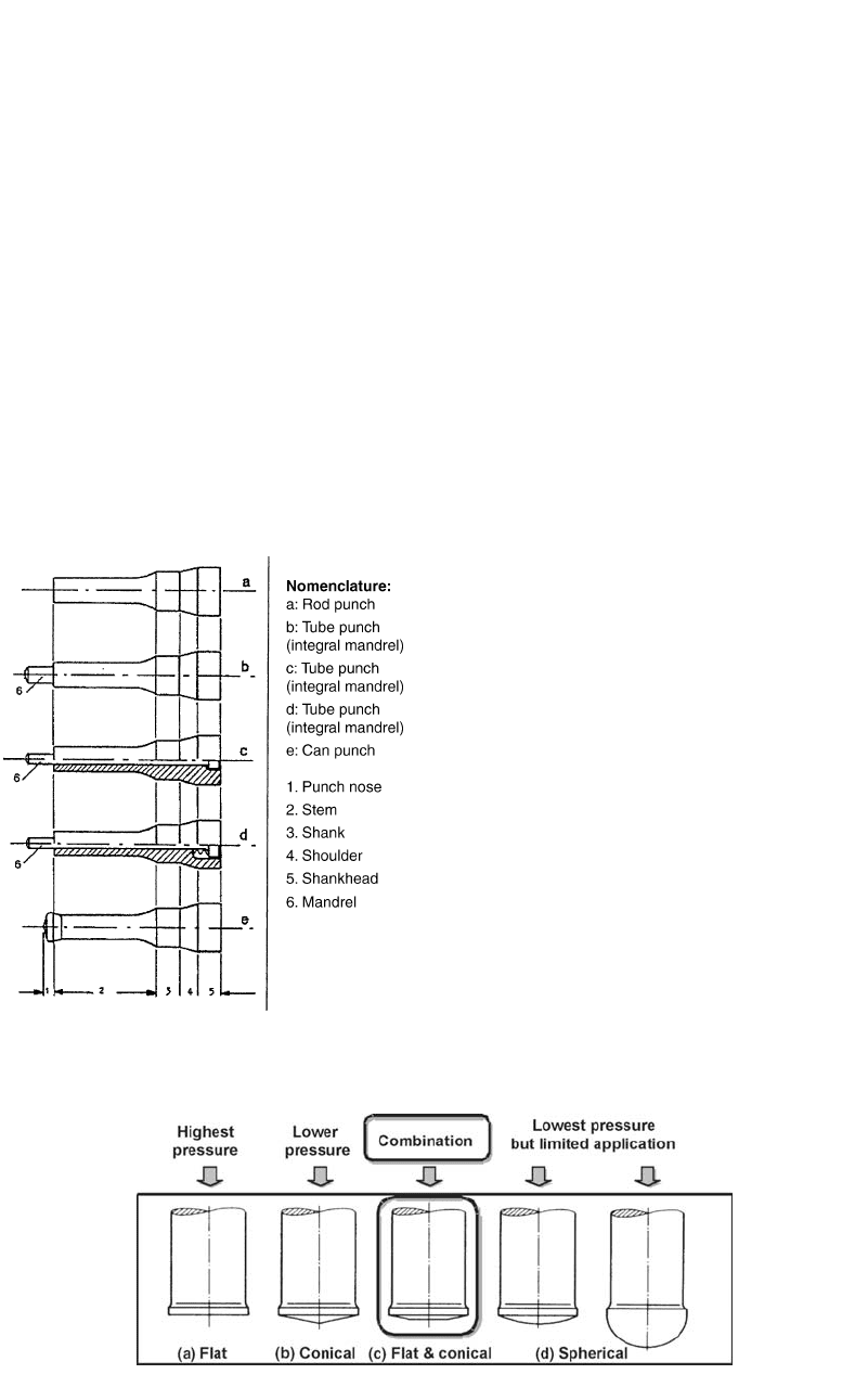
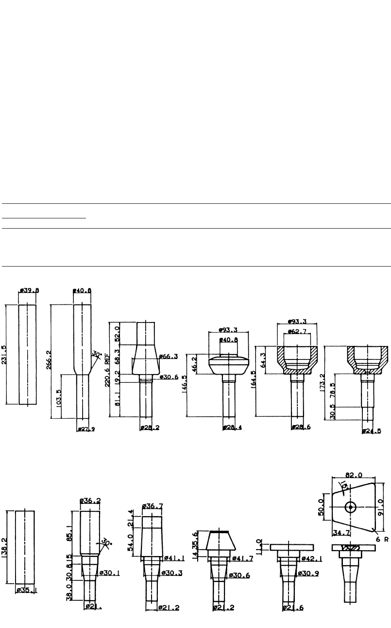
17.12 Punch Design for Cold Forging
Figure 17.15 shows some punches and man-
drels used for solid and hollow forward extru-
sion.
The design process for punches and mandrels
can be divided into the following stages:
●
Determining the forming load
●
Deciding the overall shape and proportions
of the tool. For can extrusion, the detailed
shape of the punch nose is to be determined.
●
Choosing an appropriate tool material, con-
sidering the stresses, manufacturability, tool
life, availability, and costs
228 / Cold and Hot Forging: Fundamentals and Applications
Fig. 17.15
General designs for punches used in cold extru-
sion [ICFG, 1992]
●
Verifying the design with model tests, pro-
totyping, or finite-element simulations
For punches, an approximate design guideline
is to determine the maximum compressive stress
expected in the process and comparing this with
the compressive properties of the tool material.
The punch face shape has a significant effect on
the friction force and the material flow. Figure
17.16 shows different types of punch face
shapes. The advantage of using a flat/conical
punch geometry (Fig. 17.16c) is that the lubri-
cant carrier and the lubricant cannot be separated
easily or overextended locally, as is the case with
conical faces.
Some recommendations for designing
punches are as follows:
●
Punches should be made as short as possible.
The punch will buckle if the stress exceeds
a certain level for a given length-to-diameter
ratio. The design should also avoid excessive
bending stress that may occur due to buck-
ling of the punch. Punches for can extrusion
are more susceptible to buckling failure than
those for rod or tube extrusion.
●
Large and abrupt changes in cross sections
should be avoided over the whole punch
length in order to minimize undesirable
stress concentration. The changes in the
cross sections should be done using small
cone angles and large transition radii, nicely
rounded and polished.
●
In forward extrusion, the diameter of the
punch at the deformation zone should be
chosen such that:
a. There is sufficient entry clearance for the
punch.
b. The clearance between the punch and the
die should not be very large, to avoid burr
formation.
c. The clearance should not be too small, or
else the punch will wear out due to elastic
deflection of the tooling.
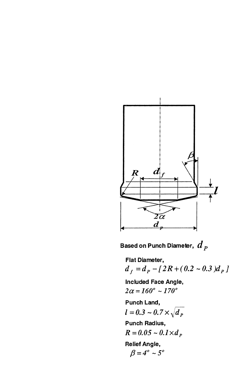
Figure 17.17 shows the parameters involved
in design for backward can extrusion punches.
The details of punch design and parameters cal-
culation can be found in the literature [ICFG,
1992, and Lange et al., 1985].
17.13 Die Design and
Shrink Fit [Lange et al.,
1985, and ICFG, 1992]
Dies for cold extrusion can be of different
configurations, depending on the design prefer-
ences or operational requirements. In general,
Fig. 17.16 Punch face shapes for backward can extrusion [Lange et al., 1985]
Cold and Warm Forging / 229
the design of dies and die assemblies requires
consideration of the following:
●
The flow stress of the workpiece material,
which is affected by strain, temperature, and
strain rate
●
The type of the process
●
The geometry of the die and the slug or pre-
form
●
Friction and lubrication
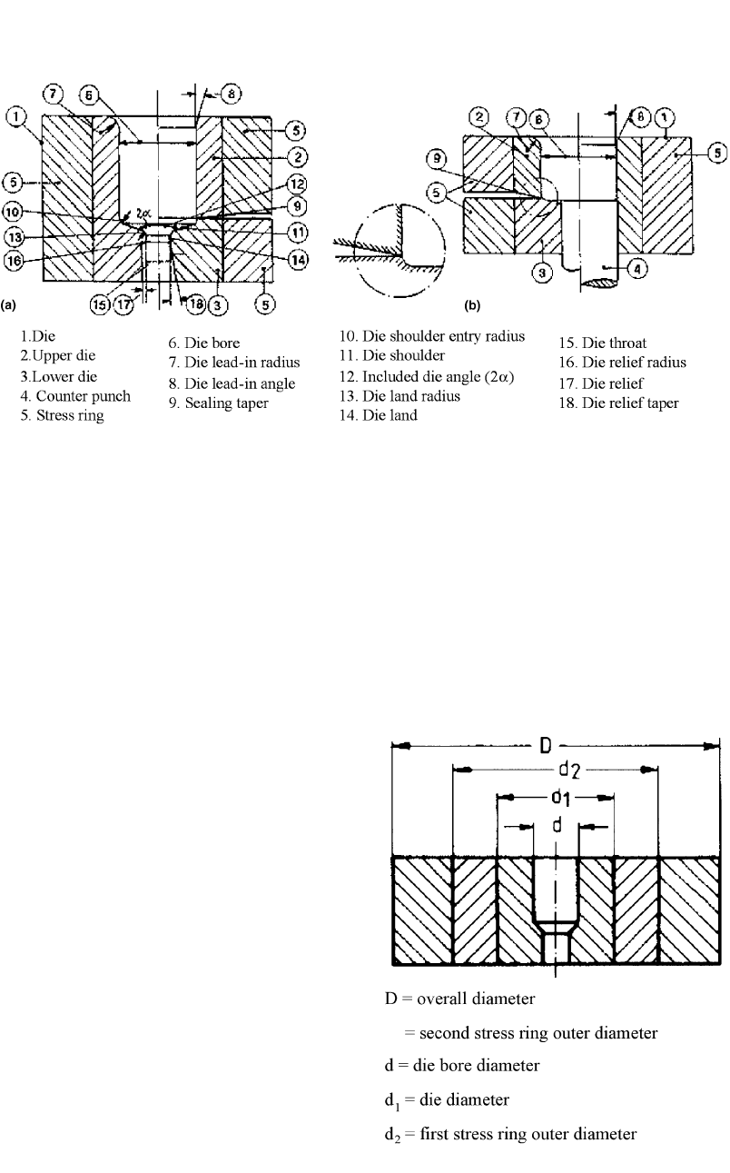
Figures 17.8(a) and (b) show the general no-
menclature for extrusion dies. One half of each
figure illustrates the use of split dies. The rec-
ommended design guidelines for the parameters
in Fig. 17.18 are as follows:
●
The die entry radius should be as large as
possible so as to minimize high stress con-
centrations.
●
The included die angle for minimum extru-
sion pressure should lie between 50 and 70
for extrusion ratios of approximately 2 and
4, respectively.
●
The die land radius should be fairly small,
i.e., between 0.008 and 0.06 in. (0.2 and 1.5
mm), depending on the diameter of the die
throat.
●
The length of the die land should be between
0.08 and 0.16 in. (2 and 4 mm), depending
on the throat diameter.
●
The die relief should be kept small to provide
guidance for the extruded rod and should be
higher than the permitted wear allowance on
the die throat.
Extrusion dies are generally very highly
stressed. One or more rings are used to assemble
the container with interference fits in order to
apply compressive stresses to the die ring or
liner. The number and diameter of the rings de-
pend on the magnitude of stresses needed and
the overall die space available in the press. Fig-
ure 17.19 shows the dies with two stress rings.
Heat treatment of stress rings is very important
to develop the desired mechanical properties.
Table 17.11 gives guidelines for the diameters
of the stress rings.
In applications where the extrusion pressure
is very high, in excess of 300 ksi (2068 MPa),
it is recommended to use stress rings that are
strip wound. Plastic deformation in conventional
stress rings makes it difficult to control the com-
pressive prestress and results in die failures.
Strip-wound containers have strength that is
twice or three times higher than the conventional
stress rings. This high strength of strip-wound
containers makes it possible to provide optimum
prestress of the die inserts, leading to an im-
provement of two to ten times in die life, de-
pending on the cold forging operation [Groen-
baek, 1997].
17.14 Process Sequence Design
In practice, cold forming requires several
stages to transform the initial simple billet ge-
Fig. 17.17
Can extrusion punch design guidelines [ICGF,
1992]
230 / Cold and Hot Forging: Fundamentals and Applications
ometry into a more complex product. One of the
major efforts required in applying the use of the
cold forging process successfully is the design
of the forming sequences for multistage forging
operations. Highly experienced die designers do
this work, and it requires both experienced judg-
ment and the application of established design
rules [Sevenler et al., 1987]. Computer-aided
tools, such as finite-element modeling (FEM)
simulations, are used to assist the die designers
while they establish the forming sequences in
cold forging [Altan et al., 1992].
In the early stages of forming sequence de-
sign, the designer draws rough sketches of the
preforms for each station. The designer then cal-
culates the volumes and tries to establish the ac-
curate workpiece dimensions. The designer may
then want to change some part or preform di-
mensions to examine various design alternatives
while keeping the workpiece volume constant.
The FEM simulation of metal flow and tool de-
flection may be required at this stage of design.
The FEM can be used as a validation tool before
tryouts. Figures 17.20 through 17.22 show some
examples of forging sequences. More examples
can be found on the CD available with this book.
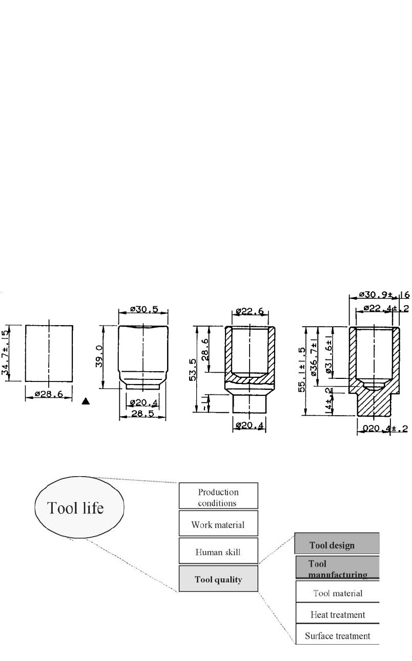
17.15 Parameters Affecting Tool Life
Tool life in cold forging is important, as it
affects the tool cost and thereby increases the
process and parts costs. Figure 17.23 shows the
various parameters that affect tool life [Yaman-
aka et al., 2002].
Tool life depends on the production condi-
tions, work material, human skills, and tool
quality. Tool quality is affected by how well the
tool is designed, the manufacturing of the tool,
the material selected, and the heat and surface
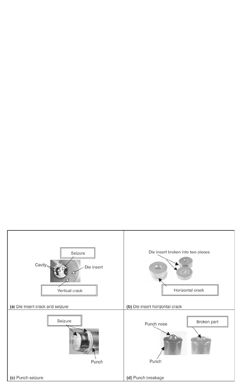
treatment conditions. Figure 17.24 shows the
typical tool defects encountered in cold forging
tooling.
Fig. 17.18 General nomenclature for extrusion dies. (a) Rod/tube extrusion. (b) Can extrusion [ICFG, 1992]
Fig. 17.19
Die with two stress rings [ICFG, 1992]
Cold and Warm Forging / 231
17.15.1 Die Failure
In general, die failure may occur in one or
more of the following forms.
Pickup and Wear [ICFG, 1992]. If extruded
components show bright areas, scratches, and
score lines in the direction of extrusion, then un-
favorable frictional conditions between the die
and workpiece result in pickup on the die. These
conditions may be caused by insufficient lubri-
cation, a rough slug surface, too rough die sur-
face (owing to incorrect manufacture or heavy
wear), too low die insert hardness, or unsuitable
tool geometry.
The die should be taken out for service as
soon as the effects of pickups are observed, so
that regrinding and finishing can be carried out.
Tool steel dies are more prone to pickup and
heavy wear than cemented carbide dies.
Fracture of Inserts [ICFG, 1992]. Die in-
serts may fail in different ways.
Axial Cracks. Fractures of this type are usu-
ally the result of overstressing, which may arise
from insufficiently high pressures.
Fig. 17.21 Forging sequence (example 2)
Fig. 17.20 Forging sequence (example 1)
Table 17.11 Guidelines for stress rings diameter calculations [ICFG, 1992]
Internal pressure
Number of
Required ratio of
overall diameter to die
ksi MPa stress rings required bore diameter (D/d) (approx.) Intermediate diameter (approx.)
Up to 150 Up to 1034 None 4 to 5 . . .
150 to 250 1034 to 1724 One 4 to 6 d
1
0.9 Dd
250 to 300 1724 to 2068 Two 4 to 6 d: d
1
:d
2
:D 1: 1.6 to 1.8: 2.5 to 3.2: 4 to 6
Note: is the Poisson’s ratio, and D, d, d
1
, and d
2
are the same as in Fig. 17.19.
232 / Cold and Hot Forging: Fundamentals and Applications
If insufficient prestressing is suspected, then
it could be increased by using additional stress
rings, increasing the overall diameter of the as-
sembly, or using stress rings of greater strength.
In all the situations, the interference must be ad-
justed appropriately.
If the die design is already considered as the
best possible, then fracture is due to excessive
extrusion pressure. The most frequent reason for
this could be high flow stress of the slug material
as a consequence of inadequate annealing or de-
parture from correct material composition.
Transverse Cracks. A transverse crack, which
is most common, is usually in one-piece rod ex-
trusion die inserts and occasionally in tube ex-
trusion dies in the vicinity of the die shoulder
entry. A similar type may also occur in the die
bore at locations corresponding to the position
of the rear face of the slug at the beginning and
end of the extrusion stroke. These are due to
stress concentration or triaxial stresses involving
a high component of axial tensile stress. In most
cases, fatigue failure (after the production of a
fairly large number of parts) is responsible.
To prevent transverse cracks, use of a tougher
die material, decreasing the hardness of a tool
steel insert by 2 to 5 points in the Rockwell C
scale, splitting the die or decreasing the die an-
gle, and/or increasing the die entry radius could
be helpful [ICFG, 1992].
17.15.2 Procedure to Improve Tool Life
Figure 17.25 describes a typical procedure to
improve tool life in the cold forging process. Ob-
servation and proper inspection of the failed tool
must be done. Based on the causes of the failures
discussed above, knowledge, and experience, a
tool failure mechanism can be assumed. Using
experience and finite-element simulations, a new
Fig. 17.23 Parameters affecting tool life in cold forging [Yamanaka, 2002]
Fig. 17.22 Forging sequence (example 3)
Cold and Warm Forging / 233
design can be suggested to overcome the tool
failure. If the new design gives a satisfactory
tool life, then it could be finalized for the pro-
cess.
17.16 Warm Forging
In cold forging of parts with relatively com-
plex geometries from high-carbon and alloy
steels, forging pressures are extremely high and
the ductility of the material is low. As a result,
short tool life and defects formed during forging
limit the economic use of the cold forging pro-
cesses. Consequently, in many cases, warm forg-
ing, i.e., forging at temperatures below recrys-
tallization temperature, is commonly used
[Altan et al., 1983]. For warm forging, steels are
usually heated between room temperature and
usual hot forging temperature. The normal tem-
perature range is considered to be 1110 to 1650
F (600 to 900 C). An exception is the warm
forging of austentic stainless steels, which usu-
ally are forged between 390 and 570 F (200 and
300 C) [ICFG, 2001b]. The process may be in-
terpreted broadly as thermomechanical process-
ing at elevated temperature to achieve the fol-
lowing advantages:
●
A reduction in flow stress. This is applicable,
in particular, to high-alloy steels. As a result,
tool stresses and forging loads are reduced
(Fig. 17.26).
●
Greater ductility of the forged part. This al-
lows more complex shapes to be forged.
●
A reduction in strain hardening. This may
reduce the number of forming and annealing
operations.
●
Greater toughness of the forged part
●
Improved accuracy as compared to hot forg-
ing
●
Enhanced product properties through grain
refinement and controlled phase transfor-
mations in heat treatable steels
As an example, variations of tensile stress and
ductility (as indicated by reduction of area) with
temperature are shown in Fig. 17.26 for 1045
steel. It can be seen that the tensile stress does
not decrease continuously with temperature.
There is a temperature range, in this case, at ap-
proximately 400 to 800 F (205 to 425 C),
wherein forging would not be recommended.
Warm forging requires determination of the op-
timum forging temperature and the suitable lu-
bricant. Selection of warm forging lubricants has
proved to be especially difficult. The factor that
limits the use of warm forging is that the tech-
Fig. 17.24 Typical defects in cold forging tools [Yamanaka et al., 2002]