Cold and Hot Forging: Fundamentals and Applications / Edited by Taylan Altan, Gracious Ngaile, Gangshu Shen
Подождите немного. Документ загружается.


CHAPTER 16
Process Modeling in Impression-Die
Forging Using Finite-Element Analysis
Manas Shirgaokar
Gracious Ngaile
Gangshu Shen
16.1 Introduction
Development of finite-element (FE) process
simulation in forging started in the late 1970s.
At that time, automatic remeshing was not avail-
able, and therefore, a considerable amount of
time was needed to complete a simple FE simu-
lation [Ngaile et al., 2002]. However, the devel-
opment of remeshing methods and the advances
in computational technology have made the in-
dustrial application of FE simulation practical.
Commercial FE simulation software is gaining
wide acceptance in the forging industry and is
fast becoming an integral part of the forging de-
sign and development process.
The main objectives of the numerical process
design in forging are to [Vasquez et al., 1999]:
●
Develop adequate die design and establish
process parameters by:
a. Process simulation to assure die fill
b. Preventing flow-induced defects such as
laps and cold shuts
c. Predicting processing limits that should
not be exceeded so that internal and sur-
face defects are avoided
d. Predicting temperatures so that part prop-
erties, friction conditions, and die wear
can be controlled
●
Improve part quality and complexity while
reducing manufacturing costs by:
a. Predicting and improving grain flow and
microstructure
b. Reducing die tryouts and lead times
c. Reducing rejects and improving material
yield
●
Predict forging load and energy as well as
tool stresses and temperatures so that:
a. Premature tool failure can be avoided.
b. The appropriate forging machines can be
selected for a given application.
Process modeling of closed-die forging using
finite-element modeling (FEM) has been applied
in aerospace forging for a couple of decades
[Howson et al., 1989, and Oh, 1982]. The goal
of using computer modeling in closed-die forg-
ing is rapid development of right-the-first-time
processes and to enhance the performance of
components through better process understand-
ing and control. In its earlier application, process
modeling helped die design engineers to pre-
view the metal flow and possible defect forma-
tion in a forging. After the forging simulation is
done, the contours of state variables, such as ef-
fective strain, effective strain rate, and tempera-
ture at any instant of time during a forging, can
be generated. The thermomechanical histories of
selected individual locations within a forging
can also be tracked [Shen et al., 1993]. These
functions of process modeling provided an in-
sight into the forging process that was not avail-
able in the old days. Integrated with the process
modeling, microstructure modeling is a new area
that has a bright future [Sellars, 1990, and Shen
et al., 2000]. Microstructure modeling allows the
right-the-first-time optimum metallurgical fea-
tures of the forging to be previewed on the com-
puter. Metallurgical aspects of forging, such as
Cold and Hot Forging Fundamentals and Applications
Taylan Altan, Gracious Ngaile, Gangshu Shen, editors, p193-209
DOI:10.1361/chff2005p193
Copyright © 2005 ASM International®
All rights reserved.
www.asminternational.org

194 / Cold and Hot Forging: Fundamentals and Applications
grain size and precipitation, can be predicted
with reasonable accuracy using computational
tools prior to committing the forging to shop tri-
als. Some of the proven practical applications of
process simulation in closed-die forging include:
●
Design of forging sequences in cold, warm,
and hot forging, including the prediction of
forming forces, die stresses, and preform
shapes
●
Prediction and optimization of flash dimen-
sions in hot forging from billet or powder
metallurgy preforms
●
Prediction of die stresses, fracture, and die
wear; improvement in process variables and
die design to reduce die failure
●
Prediction and elimination of failures, sur-
face folds, or fractures as well as internal
fractures
●
Investigation of the effect of friction on
metal flow
●
Prediction of microstructure and properties,
elastic recovery, and residual stresses
16.2 Information Flow in
Process Modeling
It is a well-known fact that product design
activity represents only a small portion, 5 to
15%, of the total production costs of a part.
However, decisions made at the design stage de-
termine the overall manufacturing, maintenance,
and support costs associated with the specific
product. Once the part is designed for a specific
process, the following steps lead to a rational
process design:
1. Establish a preliminary die design and select
process parameters by using experience-
based knowledge.
2. Verify the initial design and process condi-
tions using process modeling. For this pur-
pose it is appropriate to use well-established
commercially available computer codes.
3. Modify die design and initial selection of
process variables, as needed, based on the re-
sults of process simulation.
4. Complete the die design phase and manufac-
ture the dies.
5. Conduct die tryouts on production equip-
ment.
6. Modify die design and process conditions, if
necessary, to produce quality parts.
Hopefully, at this stage little or no modification
will be necessary, since process modeling is ex-
pected to be accurate and sufficient to make all
the necessary changes before manufacturing the
dies.
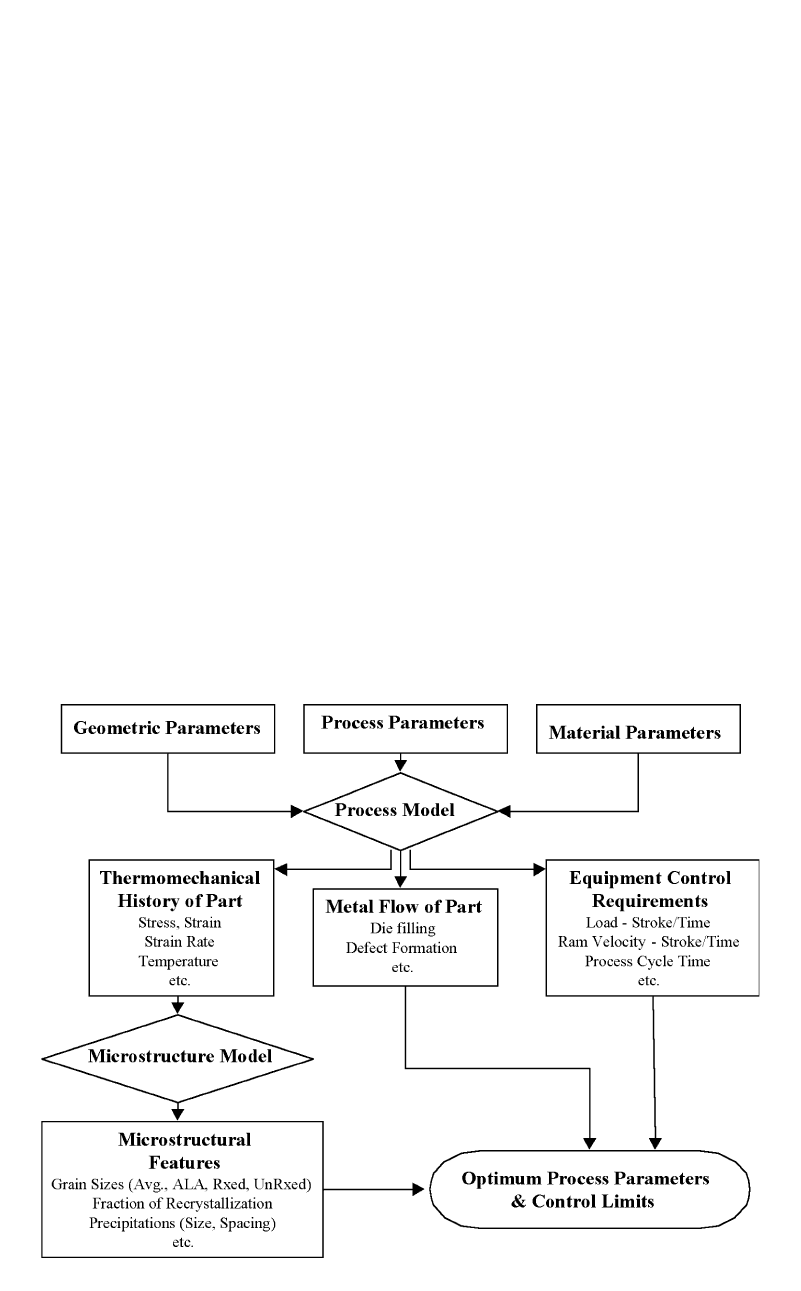
Information flow in process modeling is
shown schematically in Fig. 16.1 [Shen et al.,
2001]. The input of the geometric parameters,
process parameters, and material parameters sets
up a unique case of a closed-die forging. The
modeling is then performed to provide infor-
mation on the metal flow and thermomechanical
history of the forging, the distribution of the
state variables at any stage of the forging, and
the equipment response during forging. The his-
tories of the state variables, such as strain, strain
rate, temperature, etc., are then input to the mi-
crostructure model for microstructural feature
prediction. All of the information generated is
used for judging the closed-die forging case. The
nonsatisfaction in any of these areas will require
a new model with a set of modified process pa-
rameters until the satisfied results are obtained.
Then, the optimum process is selected for shop
practice.
16.3 Process Modeling Input
Preparing correct input for process modeling
is very important. There is a saying in computer
modeling: garbage in and garbage out. Some-
times, a time-consuming process modeling is
useless because of a small error in input prepa-
ration. Process modeling input is discussed in
terms of geometric parameters, process param-
eters, and material parameters [SFTC, 2002].
16.3.1 Geometric Parameters
The starting workpiece geometry and the die
geometry need to be defined in a closed-die forg-
ing modeling. Depending on its geometrical
complexity, a forging process can be simulated
either as a two-dimensional, axisymmetric or
plane-strain, or a three-dimensional problem. If
the process involves multiple stations, the die
geometry of each station needs to be provided.
A typical starting workpiece geometry for a
closed-die forging is a cylinder with or without
chamfers. The diameter and the height of the
cylinder are defined in the preprocessing stage.
A lot of closed-die forgings are axisymmetric,
which need a two-dimensional geometry han-
dling. Boundary conditions on specific segments
Process Modeling in Impression-Die Forging Using Finite-Element Analysis / 195
of the workpiece and dies that relate to defor-
mation and heat transfer need to be defined. For
example, for an axisymmetric cylinder to be
forged in a pair of axisymmetric dies, the nodal
velocity in the direction perpendicular to the
centerline should be defined as zero, and the heat
flux in that direction should also be defined as
zero.
16.3.2 Process Parameters
The typical process parameters to be consid-
ered in a closed-die forging include [SFTC,
2002]:
●
The environment temperature
●
The workpiece temperature
●
The die temperatures
●
The coefficients of heat transfer between the
dies and the billet and the billet and the at-
mosphere
●
The time used to transfer the workpiece from
the furnace to the dies
●
The time needed to have the workpiece rest-
ing on the bottom die
●
The workpiece and die interface heat-trans-
fer coefficient during free resting
●
The workpiece and die interface heat-trans-
fer coefficient during deformation
●
The workpiece and die interface friction, etc.
The die velocity is a very important parameter
to be defined in the modeling of a closed-die
forging. If a hydraulic press is used, depending
on the actual die speed profiles, the die velocity
can be defined as a constant or series of veloc-
ities that decrease during deformation. The ac-
tual die speed recorded from the forging can also
be used to define the die velocity profile. If a
mechanical press is used, the rpm of the fly-
wheel, the press stroke, and the distance from
the bottom dead center when the upper die
touches the part need to be defined. If a screw
press is used, the total energy, the efficiency, and
the ram displacement need to be defined. If a
hammer is used, the blow energy, the blow ef-
ficiency, the mass of the moving ram and die,
the number of blows, and the time interval be-
tween blows must be defined. Forgings per-
formed in different machines, with unique ve-
locity versus stroke characteristics, have been
simulated successfully using the commercial FE
software DEFORM (Scientific Forming Tech-
nologies Corp.) [SFTC, 2002].
Fig. 16.1 Flow chart of modeling of closed-die forging [Shen et al., 2001]

196 / Cold and Hot Forging: Fundamentals and Applications
16.3.3 Tool and Workpiece
Material Properties
In order to accurately predict the metal flow
and forming loads, it is necessary to use reliable
input data. The stress-strain relation or flow
curve is generally obtained from a compression
test. However, the test is limited in achievable
strains. In order to obtain the flow stress at large
strains and strain rates, the torsion test can be
used or, alternatively, the compression data is
extrapolated with care.
In most simulations, the tools are considered
rigid; thus, die deformation and stresses are ne-
glected. However, in precision forging opera-
tions, the relatively small elastic deformations of
the dies may influence the thermal and mechan-
ical loading conditions and the contact stress dis-
tribution at the die/workpiece interface. Thus,
die stress analysis is a crucial part of process
simulation to verify the die design and the forg-
ing process parameters.
16.3.4 Interface Conditions
(Friction and Heat Transfer)
The friction and heat-transfer conditions at
the interface between the die and the billet have
a significant effect on the metal flow and the
loads required to produce the part. In forging
simulations, due to the high contact stresses at
the interface between the workpiece and the die,
the constant shear friction factor gives better re-
sults than the coulomb friction coefficient.
The most common way to determine the shear
friction factor in forging is to perform ring com-
pression tests. From these tests, it is possible to
estimate the heat-transfer coefficient, flow stress
and friction as a function of temperature, strain
rate, strain, and forming pressure, as discussed
in Chapter 6, “Temperatures and Heat Transfer.”
Friction factors measured with the ring com-
pression test, however, are not valid for preci-
sion forging processes (hot, warm, and cold)
where the interface pressure is very high and the
surface generation is large. The friction condi-
tions change during the process due to changes
in the lubricant and the temperature at the die/
workpiece interface. In such applications, the
double cup extrusion test is recommended for
estimation of the friction factor, as discussed in
Chapter 7, “Friction and Lubrication.”
16.3.5 Material Parameters
The closed-die hot forging modeling is a cou-
pled heat-transfer and deformation simulation.
Material parameters that relate to both heat
transfer and deformation need to be defined. The
material parameters commonly used for heat-
transfer modeling are the thermal conductivity,
heat capacity, and emissivity of the workpiece
and die materials. These parameters are usually
defined as a function of temperature, The flow
stress of the workpiece material is very impor-
tant for the correct prediction of metal flow be-
havior. It is usually defined as a function of
strain, strain rate, temperature, and possible
starting microstructures. The Young’s modulus,
the Poisson’s ratio as a function of temperature,
and the thermal expansion of the die materials
are important parameters for die stress analysis.
16.4 Characteristics of
the Simulation Code
16.4.1 Mesh Generation and
Automatic Remeshing
In forging processes, the workpiece generally
undergoes large plastic deformation, and the
relative motion between the deforming material
and the die surface is significant. In the simu-
lation of such processes, the starting mesh is
well defined and can have the desired mesh den-
sity distribution. As the simulation progresses,
the mesh tends to get distorted significantly.
Hence, it is necessary to generate a new mesh
and interpolate the simulation data from the old
mesh to the new one to obtain accurate results.
Automated mesh generation (AMG) schemes
have been incorporated in commercial FE codes
for metal forming simulations. In DEFORM,
there are two tasks in AMG: 1) determination of
optimal mesh density distribution and 2) gen-
eration of the FE mesh based on the given den-
sity. The mesh density should conform to the
geometrical features of the workpiece at each
step of deformation [Wu et al., 1992]. In order
to maximize the geometric conformity, it is nec-
essary to consider mesh densities that take into
account the boundary curvature and local thick-
ness.
In DEFORM, two-dimensional (2-D) simu-
lations use quadrilateral elements, whereas
three-dimensional (3-D) simulations use tetra-
hedral elements for meshing and automatic re-
meshing [Wu et al., 1996]. With this automatic
remeshing capability, it is possible to set up a
simulation model and run it to the end with very
little interaction with the user.

Process Modeling in Impression-Die Forging Using Finite-Element Analysis / 197
duces defects in the forging. In real closed-die
forging, it is necessary to wait until the forging
is finished to see the forged part and the defect,
if there is one. The advantage of computer simu-
lation of forging is that the entire forging process
is stored in a database file in the computer and
can be tracked. Whether there is a defect formed
and how it is formed can be previewed before
the actual forging. Figure 16.2 shows the lap for-
mation for a rejected process in the design stage.
The lap formation can be eliminated by chang-
ing the workpiece geometry (the billet or pre-
form), or the die geometry, or both. The com-
puter modeling can again indicate if the
corrective measure works or not.
16.5.2 Distribution and
History of State Variables
The distribution of the state variables, such as
the strain, strain rate, and temperature, at any
stage of a closed-die forging can be plotted from
the database file saved for the forging simula-
tion. The history of these state variables can also
be tracked.
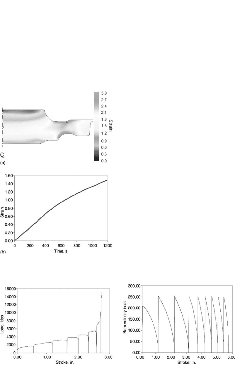
Figure 16.3(a) shows the effective strain dis-
tribution of a closed-die forging forged in an iso-
thermal press. The effective strain has a value of
0.4 to 0.9 in the bore die lock region. The region
that is in contact with the upper die has an ef-
fective strain value of 0.4 to 0.9, and the region
that is in contact with the lower die, a value of
0.7 to 0.9. With an effective strain of 2.0 to 2.8,
the bore rim transition region has the largest
strain. The effective strain value is approxi-
mately 1.5 for both the rim and the midheight of
the bore region. From the state variable distri-
bution plot, the state variable at a specific stage
of the forging is known. This specific stage,
Fig. 16.2 Lap prediction using process modeling tool
16.4.2 Reliability and
Computational Time
Several FE simulation codes are commer-
cially available for numerical simulation of forg-
ing processes, such as DEFORM (2-D and 3-D),
FORGE (2-D and 3-D) (Ternion Corp.), Qform
(2-D and 3-D), etc. In addition to a reliable FE
solver, the accurate and efficient use of metal
flow simulations require [Knoerr et al., 1992]:
●
Interactive preprocessing to provide the user
with control over the initial geometry, mesh
generation, and input data; automatic re-
meshing to allow the simulation to continue
when the distortion of the old mesh is ex-
cessive; interactive postprocessing that pro-
vides more advanced data analysis, such as
point tracking and flow line calculation
●
Appropriate input data describing the ther-
mal and physical properties of die and billet
material the heat transfer and friction at the
die/workpiece interface under the processing
conditions investigated, and the flow behav-
ior of the deforming material at the relatively
large strains that occur in practical forging
operations
●
Analysis capabilities that are able to perform
the process simulation with rigid dies to re-
duce calculation time and to use contact
stresses and temperature distribution esti-
mated with the process simulation using
rigid dies to perform elastic-plastic die stress
analysis
The time required to run a simulation depends
on the computer used and the amount of memory
and workload the computer has. However, with
today’s computers, it is possible to run a 2-D
simulation in a couple of hours, while a 3-D
simulation can take anywhere between a day to
a week, depending on the part complexity [Wu
et al., 1996].
16.5 Process Modeling Output
The process modeling provides extensive in-
formation of the forging process. The output of
process modeling can be discussed in terms of
the metal flow, the distribution and history of
state variables, the equipment response during
forging, and the microstructure of the forging.
16.5.1 Metal Flow
The information on metal flow is very impor-
tant for die design. Improper metal flow pro-
198 / Cold and Hot Forging: Fundamentals and Applications
shown in Fig. 16.3(a), is the end of the forging.
The distribution of the state variables can be
plotted for any other stages of forging as well.
Figure 16.3(b) shows the effective strain ver-
sus time of a material point located at midheight
of the bore section of the forging, as shown in
Fig. 16.3(a). In this isothermal forging case, a
20 min deformation time was used, as shown in
the figure. The final strain value, 1.5, shown in
Fig. 16.3(b) is in agreement with the value
shown in the distribution plot in Fig. 16.3(a).
The history plot of state variables (strain, strain
rate, and temperature) provides valuable infor-
mation on the thermomechanical history of the
forging that determines its mechanical proper-
ties.
16.5.3 Equipment Response/Hammer
Forging
Process modeling also provides the informa-
tion regarding the response of the equipment.
Examples of equipment response discussed here
are forging load and ram velocity of hammer
forging. The information is usually not available
in the hammer shop. However, it is useful for
understanding the hammer response to a forging
process.
Figure 16.4 shows the load versus stroke pre-
dicted for a hammer forging operation. The fig-
ure shows that there are eight blows in the ham-
mer operation. Each ends with a zero load. The
stroke in the figure is the stroke of the ram/die.
The zero stroke refers to the position of the die,
where the first die/workpiece contact occurs dur-
ing forging. This zero position is the same for
all of the eight hammer blows. With the increase
in the number of blows, the load increases and
the stroke per blow decreases. The last blow of
the sequence has the shortest stroke. This be-
havior is very real for hammer forging opera-
tions. During a hammer forging operation, the
workpiece increases its contact area with the
dies, which increases the forging load. The total
available blow energy is fixed for a hammer.
With the increase in forging load, the length of
Fig. 16.4
Load versus stroke obtained from a hammer forg-
ing simulation
Fig. 16.5
Ram velocity versus stroke obtained from a ham-
mer forging simulation
Fig. 16.3
(a) Effective strain distribution and (b) the effective
strain history of the center location of a closed-die
forging
Process Modeling in Impression-Die Forging Using Finite-Element Analysis / 199
stroke is reduced. Moreover, the blow efficiency,
which is the ratio between the energy used for
deformation and the total blow energy, is also
reduced with the increase in forging load. Thus,
a smaller amount of energy is available toward
the end of a blow sequence and with the de-
crease in the stroke per blow.
Figure 16.5 gives the ram velocity versus
stroke obtained from a simulation of another
hammer forging process. There are nine blows
for this hammer operation. The velocity of the
first blow was smaller than the other eight blows,
because a soft blow was used initially to locate
the workpiece. In a soft blow, there is only a
portion of blow energy applied to the workpiece.
Thus, the first blow has a smaller starting ram
velocity. After the first blow, full energy was ap-
plied to the forging. Thus, the starting ram ve-
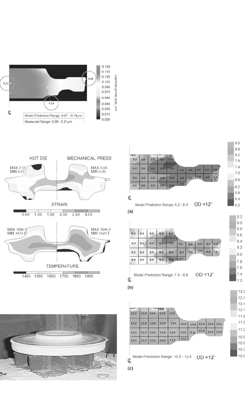
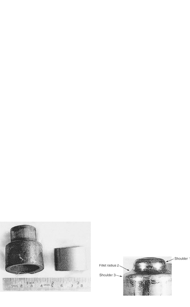
Fig. 16.8
Rene 88 experimental part out of forging press
[Hardwicke et al., 2000]
Fig. 16.7
Comparisons of hot-die forging and mechanical
press forging of an experimental part using process
modeling
Fig. 16.9
Predicted model and optically measured grain
sizes in the three developmental Rene´ 88DT disks
with (a) coarse, (b) medium, and (c) fine grains [Hardwicke et al.,
2000]
Fig. 16.6
Prediction of the distribution of the size (lm) of
gamma prime for a Rene 88 experimental forging

200 / Cold and Hot Forging: Fundamentals and Applications
locity for the rest of the blows was the same.
There is always an energy loss to surroundings
in a hammer blow. Therefore, blow efficiency
needs to be factored in for each hammer blow.
However, the blow efficiency only has an effect
after the ram/die workpiece are in contact.
Hence, blow efficiency does not influence the
starting velocity of the ram/die. It is factored in
during the blow. The decay in ram velocity in
each blow is a result of both the energy con-
sumption in deforming the workpiece and the
energy lost to the surroundings.
16.5.4 Microstructures in Superalloys
Microstructure and property modeling is now
the major emphasis in advanced forging process
design and improvement, especially in forging
aerospace alloys such as nickel and titanium su-
peralloys. The development and utilization of
physical metallurgy-based microstructure mod-
els and the integration of the models with finite-
element analysis has allowed for microstructure
prediction by computer. Two important micro-
structural features of superalloy forgings are the
grain size and the gamma-prime precipitation.
The grain size modeling is discussed in detail in
Chapter 19, “Microstructure Modeling in Su-
peralloy Forging.” The prediction of gamma-
prime distribution is discussed here. Gamma
prime is a very important precipitation phase in
strengthening superalloys. The size and spacing
are two features of interest in gamma-prime pre-
cipitation. Figure 16.6 shows the prediction of
the distribution of the size of gamma prime of
an experimental nickel-base superalloy forging,
Rene 88, coupled with a few measurement
points. The measurement made is in the range
of 0.07 to 0.21 lm. The model predicts a range
of 0.08 to 0.14 lm. The fine gamma prime was
correctly predicted and the coarser gamma prime
was underpredicted, which pointed out the need
for further improvement of the gamma-prime
model. The microstructure prediction feature is
useful for the process development for closed-
die forging.
16.6 Examples of
Modeling Applications
One of the major concerns in the research of
manufacturing processes is to find the optimum
production conditions in order to reduce pro-
duction costs and lead-time. In order to optimize
a process, the effect of the most important pro-
cess parameters has to be investigated. Con-
ducting experiments can be a very time-consum-
ing and expensive process. It is possible to
reduce the number of necessary experiments by
using FEM-based simulation of metal forming
processes.
Fig. 16.10 Investigation of defects in ring gear forging using FEM [Jenkins et al., 1989]
Process Modeling in Impression-Die Forging Using Finite-Element Analysis / 201
16.6.1 Process Modeling for
Equipment Selection
Figure 16.7 illustrates an example of the ap-
plication of process modeling to select the most
suitable equipment (a hot-die hydraulic press or
a mechanical press) for forging a superalloy part
in a hot-die hydraulic press or a mechanical
press. Effective strain and temperature distribu-
tions are compared in this figure. There was a
preferred strain and temperature window for the
selection of the process to meet the customer’s
property requirements. In this example, the hot-
die forging appears to generate better strain and
temperature distributions than the mechanical
press.
16.6.2 Optimization of Microstructure in
Forging Jet Engine Disks
For manufacturing superalloy disks for jet en-
gines, it is extremely important to meet specific
grain size requirements. A disk of fine grain pro-
duces excellent tensile and fatigue properties but
with reduction in creep property. A disk with a
medium grain size yields balanced tensile and
creep properties. A coarse grain disk provides
excellent creep properties with a lower tensile
strength. Disks used in different sections of a jet
engine require different grain sizes and proper-
ties. A new disk product can be defined by meet-
ing new requirements for distribution of grain
size and related properties.
Process modeling coupled with microstruc-
ture modeling was used to develop processes to
produce disks with different grain sizes for a po-
tential new product. The specific goal was to
produce Rene 88 (a nickel-base superalloy)
disks with coarse (ASTM 6), medium (ASTM
8), and fine (ASTM 12) grain sizes. The micro-
structure modeling provided possible process
windows for producing each disk with the tar-
geted grain size. The process modeling, using
FEM code DEFORM, provided the actual ther-
momechanical histories of each disk. The mi-
crostructure model developed for Rene 88 was
integrated to DEFORM postprocessing module,
where the user-defined subroutine can be linked
with DEFORM. During the postprocessing in
DEFORM, the entire thermomechanical history
experienced in each local point and the starting
grain size at that point were used to calculate the
final grain size.
With the guidance from the process modeling
integrated with microstructure modeling, after a
couple of iterations, processing conditions were
selected for producing disks with the three tar-
geted grain sizes: ASTM 6 (coarse), ASTM 8
(medium), and ASTM 12 (fine). The actual forg-
ing process was performed for a reality check.
One forged disk is shown in Fig. 16.8. The grain
sizes obtained from three production processes
of the disks were actually uniform ASTM 5–6,
ASTM 7–9, and ASTM 12–13. Each disk hit its
assigned grain size goal, respectively, and there
were no abnormal grains observed on any of the
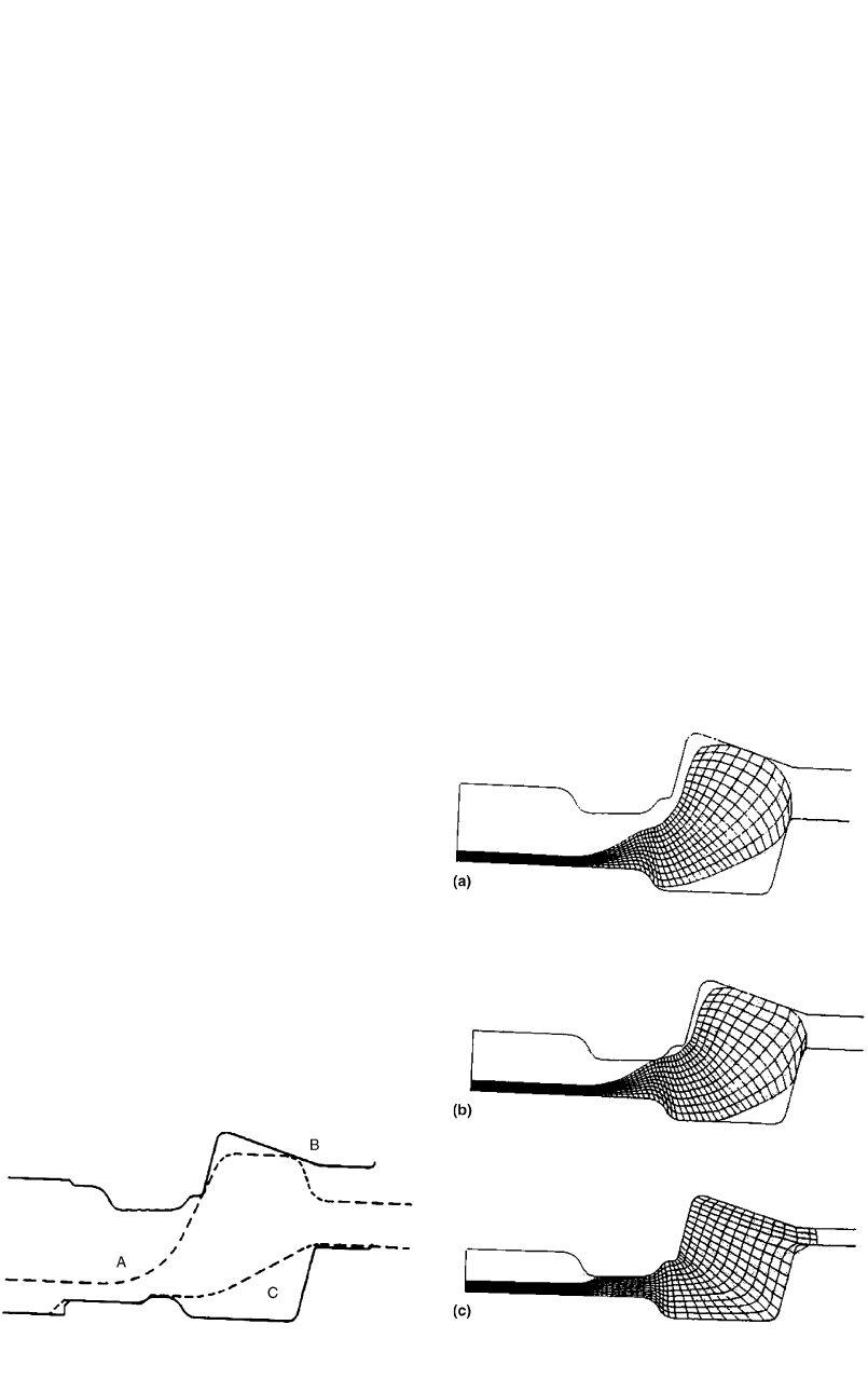
Fig. 16.11
Modified blocker design (broken lines) posi-
tioned in the open finisher dies (solid lines) [Jen-
kins et al., 1989]
Fig. 16.12
Deformed mesh of the finishing simulation with
the modified blocker design [Jenkins et al.,
1989]
202 / Cold and Hot Forging: Fundamentals and Applications
disks. Figure 16.9 compares the grain sizes ob-
tained from the model prediction (color coded)
and the optical rating (number in the block) for
the three disks [Hardwicke et al., 2000]. The
measurements agree well with the predictions in
all of the three cases. In the coarse and fine-
grained disks, the model predicted two small die
lock regions (where metal flow is prevented),
where the grain size is a little different than the
bulk. The measured grain sizes in the disk
proved this phenomenon. However, the complex
friction phenomenon in real forgings makes it
difficult to predict the exact die lock location.
The success in producing disks with the required
grain size was attributed to both the selection of
proper process conditions aided by the process
and grain size modeling as well as good pro-
duction process control.
16.6.3 Investigation of Defect
Formation in Ring Gear Forging
The process analyzed was the forging of an
automotive ring gear blank [Jenkins et al.,
1989]. In production, the part is hot forged from
AISI 4320 steel in three sets of dies. The dies
were of H11 steel, lubricated with a graphite and
water mixture and maintained at approximately
300 ⬚F (150 ⬚C).
The first step in the manufacturing process in-
volves cold shearing the billets from stock and
induction heating them to 2200 ⬚F (1200 ⬚C).
Next, a billet is placed in the busting dies and
upset (Fig. 16.10a). It is then transferred to a
blocker die and forged (Fig. 16.10b) and finally
transferred to and forged in a finisher die (Fig.
16.10c). During initial forging trials, buckling
flow in the blocker dies caused a lap to be
formed intermittently around the circumference
of the part (Fig. 16.10d). As the finish dies filled,
the lap worsened. Because of this defect, the part
was rejected, and hence, a new blocker die de-
sign was required.
The following observations were made during
simulation of the process:
●
The sharp corner radius and steep angle of
the inside wall on the upper die resulted in
the formation of a gap between the inside die
wall and the workpiece.
●
As the workpiece contacted the uppermost
surface of the top die and began upsetting,
the inside surface of the blocker began to
buckle.
●
The radial flow from the web region forced
the buckle out toward the outer die walls,
and as the upsetting and radial flow com-
bined, the buckling became more severe.
To counter the above problem, the following
modification was made to the original blocker
design:
●
The corner radius (region A of Fig. 16.11)
was increased by a factor of 2 to aid the
metal flow around the corner.
●
The angle of the top surface of the upper die
(region B of Fig. 16.11) was decreased until
it was horizontal to increase the height of the
blocker.
●
The outer wall of the lower die (region C of
Fig. 16.11) was modified so that upsetting
flow from the top die would fill voids in the
upper die cavity instead of voids in the lower
die cavity.
Figure 16.12 shows the die fill in the simu-
lation run with the new blocker design. At the
start of the working stroke, the workpiece fol-
lowed the walls of the upper and lower die. With
Fig. 16.13
Automotive component formed by forward/
backward hot forging process [Brucelle et al.,
1999]
Fig. 16.14
Cracks formed as a result of thermal cycling
[Brucelle et al., 1999]