Cold and Hot Forging: Fundamentals and Applications / Edited by Taylan Altan, Gracious Ngaile, Gangshu Shen
Подождите немного. Документ загружается.

162 / Cold and Hot Forging: Fundamentals and Applications
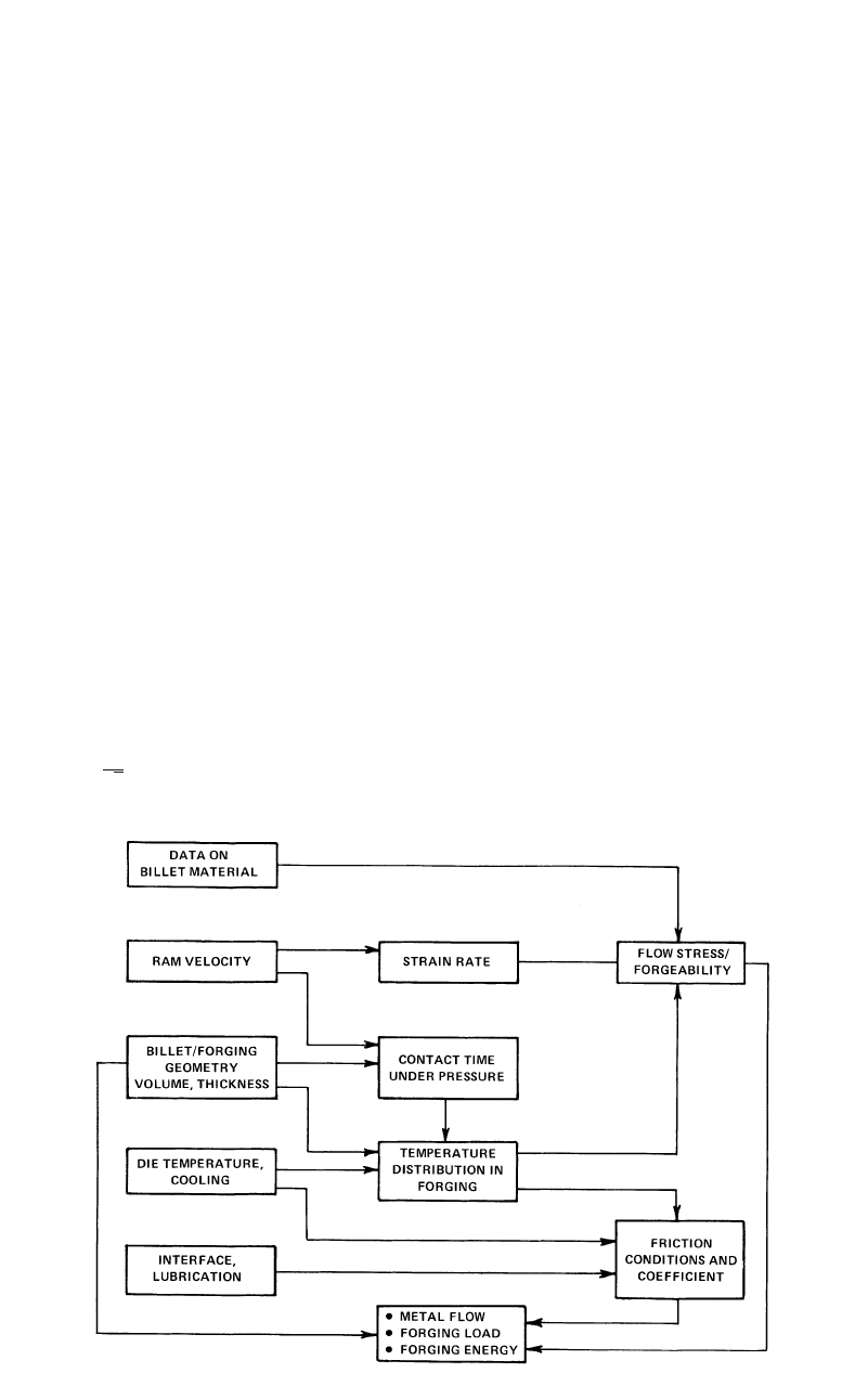
Fig. 14.3 Variables in forging
●
The part tolerances. Hydraulic and screw
presses, for example, operate with kissing
dies, i.e., the dies have flat surfaces that con-
tact each other at the end of each working
stroke of the forging press. This allows very
close control of the thickness tolerances even
if the flow stress and friction conditions
change during a production run. Ram guid-
ing, stiffness of the press frame, and drive
also contribute to tolerances that can be
achieved in forging.
14.2.3 Friction and Lubrication
The flow of metal in forging is caused by the
pressure transmitted from the dies to the deform-
ing material; therefore, the friction conditions at
the die/material interface are extremely impor-
tant and influence the die stresses and the forg-
ing load as well as the wear of the dies. In order
to evaluate the performances of various lubri-
cants and to be able to predict forming pressures,
it is necessary to express the interface friction
quantitatively, in terms of a factor or coefficient.
In forging, the frictional shear stress, s, is most
commonly expressed as:
m
s ⳱ f ¯r ⳱ ¯r (Eq 14.1)
3
冪
where s is the frictional shear stress, f is the fric-
tion factor, and m is the shear friction factor (0
m 1).
For various forming conditions, the values of
m vary as follows:
●
m ⳱ 0.05 to 0.15 in cold forging of steels,
aluminum alloys, and copper, using conven-
tional phosphate soap lubricants or oils
●
m ⳱ 0.2 to 0.4 in hot forging of steels, cop-
per, and aluminum alloys with graphite-
based lubricants
●
m ⳱ 0.1 to 0.3 in hot forging of titanium
and high-temperature alloys with glass lu-
bricants
●
m ⳱ 0.7 to 1 when no lubricant is used, e.g.,
in hot rolling of plates or slabs and in non-
lubricated extrusion of aluminum alloys
14.2.4 Heat Transfer and Temperatures
Heat transfer between the forged material and
the dies influences the lubrication conditions, die
life, properties of the forged product, and die fill.
Often, temperatures that exist in the material
during forging are the most significant variables
influencing the success and economics of a
given forging operation. In forging, the magni-
tudes and distribution of temperatures depend
mainly on:
Process Design in Impression-Die Forging / 163
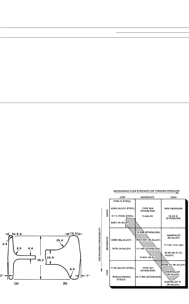
Fig. 14.4
Comparison of typical design limits for rib-web-
type structural forgings of (a) aluminum alloys and
(b) nickel-base superalloys (all dimensions are in mm) [Sabroff et
al., 1968]
Table 14.1 Hot forging temperatures of different metals and alloys [Sabroff et al., 1968]
Approximate range of forging temperature
Metal or alloy F C
Aluminum alloys (least difficult) 750–1020 400–550
Magnesium alloys 480–660 250–350
Copper alloys 1110–1650 600–900
Carbon and low-alloy steels 1560–2100 850–1150
Martensitic stainless steels 2010–2280 1100–1250
Maraging steels 2010–2280 1100–1250
Austenitic stainless steels 2010–2280 1100–1250
Nickel alloys 1830–2100 1000–1150
Semiaustenitic precipitation-hardenable stainless steels 2010–2280 1100–1250
Titanium alloys 1290–1740 700–950
Iron-base superalloys 1920–2160 1050–1180
Cobalt-base superalloys 2160–2280 1180–1250
Niobium alloys 1740–2100 950–1150
Tantalum alloys 1920–2460 1050–1350
Molybdenum alloys 2100–2460 1150–1350
Nickel-base superalloys 1920–2190 1050–1200
Tungsten alloys (most difficult) 2190–2370 1200–1300
Fig. 14.5
Generalized diagram illustrating the influence of
forgeability and flow stress on die filling [Sabroff
et al., 1968]
●
The initial material and die temperatures
●
Heat generated due to plastic deformation
and friction at the die/material interface
●
Heat transfer between the deforming mate-
rial and the dies as well as between the dies
and the environment (air, coolant, lubricant)
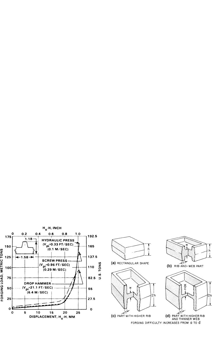
The effect of contact time on temperatures
and forging load is illustrated in Fig. 14.6, where
the load-displacement curves are given for hot
forging of a steel part using different types of
forging equipment. These curves illustrate that,
due to strain rate and temperature effects, for the
same forging process, different forging loads
and energies are required by different presses.
For the hammer, the forging load is initially
higher due to strain-rate effects, but the maxi-
mum load is lower than for either hydraulic or
screw presses. The reason for this is that in the
presses, the extruded flash cools rapidly,
whereas in the hammer, the flash temperature
remains nearly the same as the initial stock tem-
perature. Thus, in hot forming, not only the ma-
terial and the formed shape but also the type of
equipment used (rate of deformation and die
chilling effects) determine the metal flow behav-
ior and the forming load and energy required for
the process. Surface tearing and cracking or de-
velopment of shear bands on the formed material
often can be explained by excessive chilling of
the surface layers of the formed part near the
die/material interface.
164 / Cold and Hot Forging: Fundamentals and Applications
Fig. 14.7
Rectangular shape and three modifications show-
ing increasing forging difficulty with increasing rib
height and decreasing web thickness [Sabroff et al., 1968]
Fig. 14.6
Load-displacement curves for the same part forged
in three different machines with three differentram
speeds (dimensions of the part in inches, initial temperature ⳱
2012 F, or 1100 C) [Altan et al., 1973]
14.2.5 Production Lot
Size and Tolerances
As is the case in all manufacturing operations,
these two factors have a significant influence on
die design in forging. If the production lot size
is large, the main reason for changing the dies
would be die wear. In this case, die materials
and their hardnesses would be selected to be es-
pecially wear resistant even if they are made
from somewhat expensive alloys. The preform-
ing and the finishing dies are designed such that
relatively little material movement is allowed in
the finisher dies; thus, the finisher dies, which
determine the final part dimensions, will not
wear out easily.
If the production lot size is small, as is the
case in the aerospace forging industry, die wear
is not a major problem, but die costs are very
significant because these costs must be amor-
tized over a smaller number of parts. As a result,
some of the preforming or blocker dies may be
omitted even if this would cause the use of more
billet material. Also, in this case, the dies must
be changed more often than in large-scale pro-
duction. Therefore, quick die-changing and au-
tomatic die-holding mechanisms are required,
for economic production.
Forging tolerances are very important in de-
signing the die holders and die inserts, because
they depend considerably on the manufacturing
tolerances and elastic deflections of the dies dur-
ing forging. Precision forging of gears and
blades, for example, require not only very close
manufacturing accuracies on the dies but also
close control of die temperatures. In addition,
often it is necessary to estimate the changes in
die dimensions under forging conditions so that
corrections can be made while designing and
manufacturing these dies. Die dimensions vary
during the forging operation because of thermal
expansion, mechanical loading during assem-
bling of the dies in a holder, and mechanical
loading during the forging process itself.
14.3 Shape Complexity in Forging
The main objective of forging process design
is to ensure adequate metal flow in the dies so
that the desired finish part geometry can be ob-
tained without any external or internal defects.
Metal flow is greatly influenced by part or die
geometry. Often, several operations (preforming
or blocking) are needed to achieve gradual flow
of the metal from an initially simple shape (cyl-
inder or round-cornered square billet) into the
more complex shape of the final forging. In a
general sense, spherical and blocklike shapes are
the easiest to forge in impression or closed dies.
Parts with long thin sections or projections
(webs and ribs) are more difficult to forge, be-
cause they have more surface area per unit vol-
ume. Such variations in shape maximize the ef-
fects of friction and temperature changes and
hence influence the final pressure required to fill
the die cavities. There is a direct relationship

Process Design in Impression-Die Forging / 165
between the surface-to-volume ratio of a forging
and the difficulty of producing the forging.
The ease of forging more complex shapes de-
pends on the relative proportions of vertical and
horizontal projections on the part. Figure 14.7 is
a schematic representation of the effects of
shape on forging difficulties. Parts “C” and “D”
would require not only higher forging loads but
also at least one more forging operation than
parts “A” and “B” to ensure die filling.
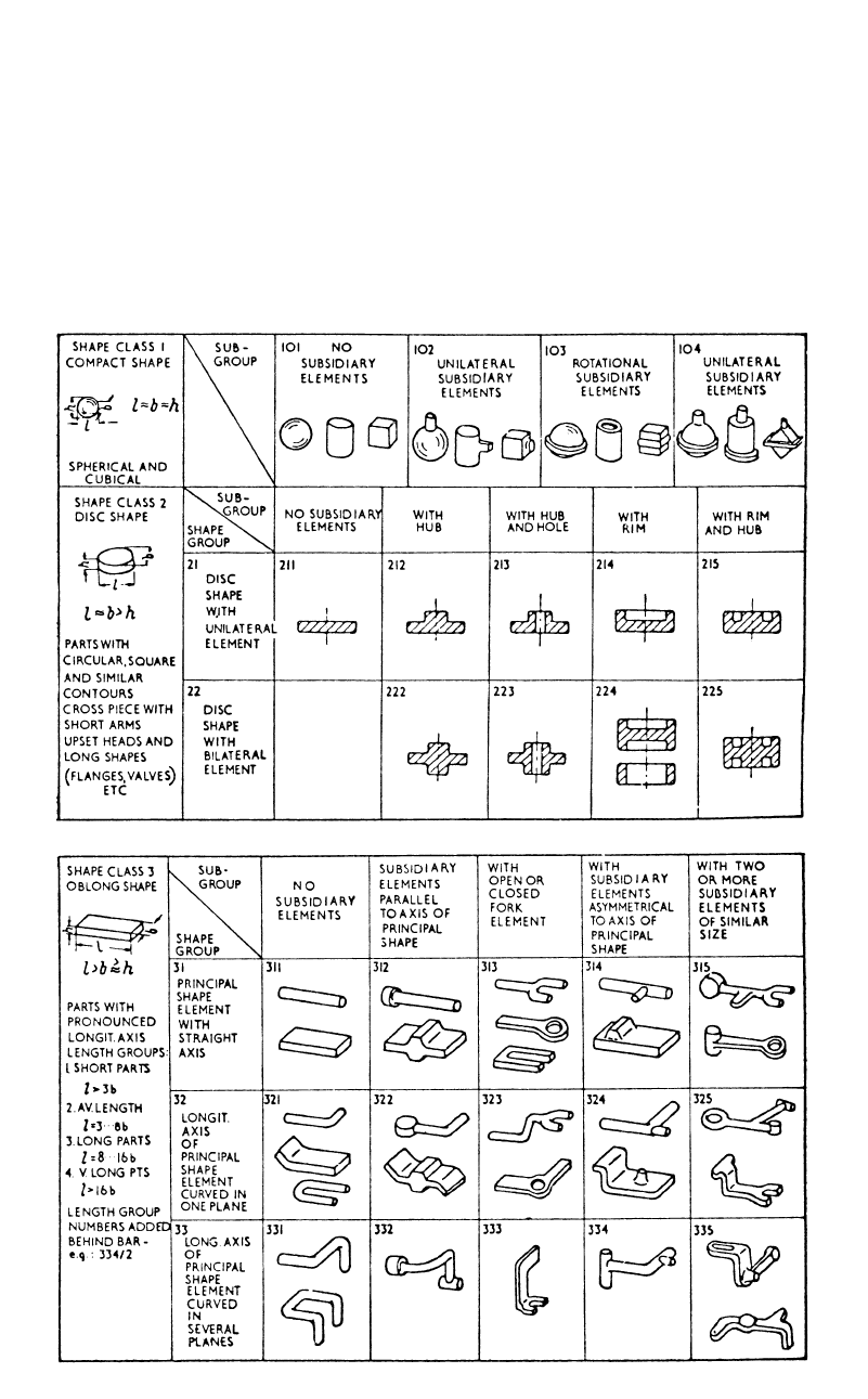
As shown in Fig. 14.8, the majority of forg-
ings can be classified into three main groups
[Spies, 1959]:
●
Compact shape, spherical and cubical shape
(class 1)
●
Disc shape (class 2)
●
Oblong shape (class 3)
The first group of compact shapes has the
three major dimensions, namely, the length (l),
width (w), and height (h) approximately equal.
The number of parts that fall into this group is
rather small.
The second group consists of disk shapes, for
which two of the three dimensions (length and
width) are approximately equal and are larger
than the height (h). All the round forgings be-
long to this group, which includes approxi-
mately 30% of all the commonly used forgings.
The third group of forgings consists of long
shapes, which have one dimension significantly
larger than the other two (l b ⱖ h).
These three basic groups are further subdi-
vided into subgroups depending on the presence
and type of elements subsidiary to the basic
shape. This “shape classification” is useful for
practical purposes, such as for estimating costs
and for predicting preforming steps. This
method is, however, not entirely quantitative and
requires some subjective evaluation based on
past experience.
A quantitative value called the “shape diffi-
culty factor” has been suggested by Teterin et
al., 1968, for expressing the geometrical com-
plexity of round forgings (having one axis of
rotational symmetry). A “longitudinal shape fac-
tor,” ␣, is defined as:
X
f
␣ ⳱ (Eq 14.1)
X
c
with
2
P
X ⳱ (Eq 14.2)
f
F
and
2
P
c
X ⳱ (Eq 14.3)
c
F
c
where P is the perimeter of the axial cross sec-
tion of the forging, F is the surface area of the
axial cross section of the forging (surface that
includes the entire axis of symmetry), P
c
is the
perimeter of the axial cross section of the cyl-
inder that circumscribes the forging, and F
c
is
the surface area of the axial cross section of the
cylinder that circumscribes the forging. Because
the circumscribing cylinder has the maximum
diameter and the maximum height of the forg-
ing, the factor ␣ represents a comparison of the
shape of the forging with that of the cylinder.
On round forgings, bosses and rims placed
farther from the center are increasingly more dif-
ficult to forge. Therefore, a “lateral shape fac-
tor,” b, is defined as:
2R
g
b ⳱ (Eq 14.4)
R
c
where R
g
is the radial distance from the sym-
metry axis to the center of gravity of half of the
cross section, and R
c
is the maximum radius of
the forged piece, which is equal to the radius of
the circumscribing cylinder.
A “shape difficulty factor,” S, incorporating
both the longitudinal and lateral factors is de-
fined as:
S ⳱ ␣b (Eq 14.5)
The factor S expresses the complexity of a
half cross section of a round forging with respect
to that of the circumscribing cylinder. In round
forgings, during the forging operation, the ma-
terial is moved laterally down (toward the ends
of the cylinder) from the center, which is con-
sidered to be at the “neutral axis.” In a nonsym-
metric forging the material is still moved out
laterally from the “neutral surface.” Thus, once
this neutral surface is defined, a “shape difficulty
factor” can also be calculated in nonsymmetric
forgings.
14.4 Design of Finisher Dies
Using the shape complexity and the forging
material as guidelines, the forging process en-
166 / Cold and Hot Forging: Fundamentals and Applications
Fig. 14.8 Classification of forging shapes [Spies, 1959]
gineer establishes the forging sequence (number
of forging operations) and designs the dies for
each operation, starting with the finisher dies.
The most critical information necessary for forg-
ing die design is the geometry and the material
of the forging to be produced. The forging ge-
ometry in turn is obtained from the machined
part drawing by modifying this part to facilitate
forging. Starting with the forging geometry, the
die designer first designs the finisher dies by:
●
Selecting the appropriate die block size and
the flash dimensions
●
Estimating the forging load and stresses to
ascertain that the dies are not subjected to
excessive loading
Process Design in Impression-Die Forging / 167
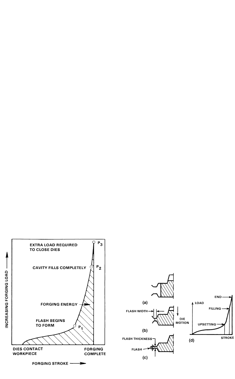
Fig. 14.10
Metal flow and the corresponding load-stroke
curve. (a) Upsetting. (b) Filling. (c) End. (d) Load-
stroke curve [Altan et al., 1983]
Fig. 14.9
Typical load-stroke curve for closed-die forging
[Altan et al., 1983]
The geometry of the finisher die is essentially
that of the finish forging augmented by flash
configuration. In designing finisher dies, the di-
mensions of the flash should be optimized. The
designer must make a compromise: on the one
hand, to fill the die cavity it is desirable to in-
crease the die stresses by restricting the flash di-
mensions (thinner and wider flash on the dies);
but, on the other hand, the designer should not
allow the forging pressure to reach a high value,
which may cause die breakage due to mechani-
cal fatigue. To analyze stresses, “slab method of
analysis” or process simulation using finite-ele-
ment method (FEM)-based computer codes is
generally used. The FEM approach is discussed
later.
By modifying the flash dimensions, the die
and material temperatures, the press speed, and
the friction factor, the die designer is able to
evaluate the influence of these factors on the
forging stresses and loads. Thus, conditions that
appear most favorable can be selected. In addi-
tion, the calculated forging stress distribution
can be utilized for estimating the local die
stresses in the dies by means of elastic FEM
analysis. After these forging stresses and loads
are estimated, it is possible to determine the cen-
ter of loading for the forging in order to locate
the die cavities in the press, such that off-center
loading is reduced.
14.4.1 Flash Design and Forging Load
The flash dimensions and the billet dimen-
sions influence the flash allowance, forging load,
forging energy, and the die life. The selection of
these variables influences the quality of the
forged part and the magnitude of flash allow-
ance, forging load, and the die life. The influence
of flash thickness and flash-land width on the
forging pressure is reasonably well understood
from a qualitative point of view. The forging
pressure increases with:
●
Decreasing flash thickness
●
Increasing flash-land width because of the
combinations of increasing restriction, in-
creasing frictional forces, and decreasing
metal temperatures at the flash gap
A typical load-versus-stroke curve from an
impression-die forging operation is shown in
Fig. 14.9. Loads are relatively low until the more
difficult details are partly filled and the metal
reached the flash opening (Fig. 14.10). This
stage corresponds to point P
1
in Fig. 14.9. For
successful forging, two conditions must be ful-
filled when this point is reached: A sufficient
volume of metal must be trapped within the con-
fines of the die to fill the remaining cavities, and
extrusion of metal through the narrowing gap of
the flash opening must be more difficult than
filling of the more intricate detail in the die.
As the dies continue to close, the load in-
creases sharply to point P
2
, the stage at which
the die cavity is filled completely. Ideally, at this
point the cavity pressure provided by the flash
geometry should be just sufficient to fill the en-
168 / Cold and Hot Forging: Fundamentals and Applications
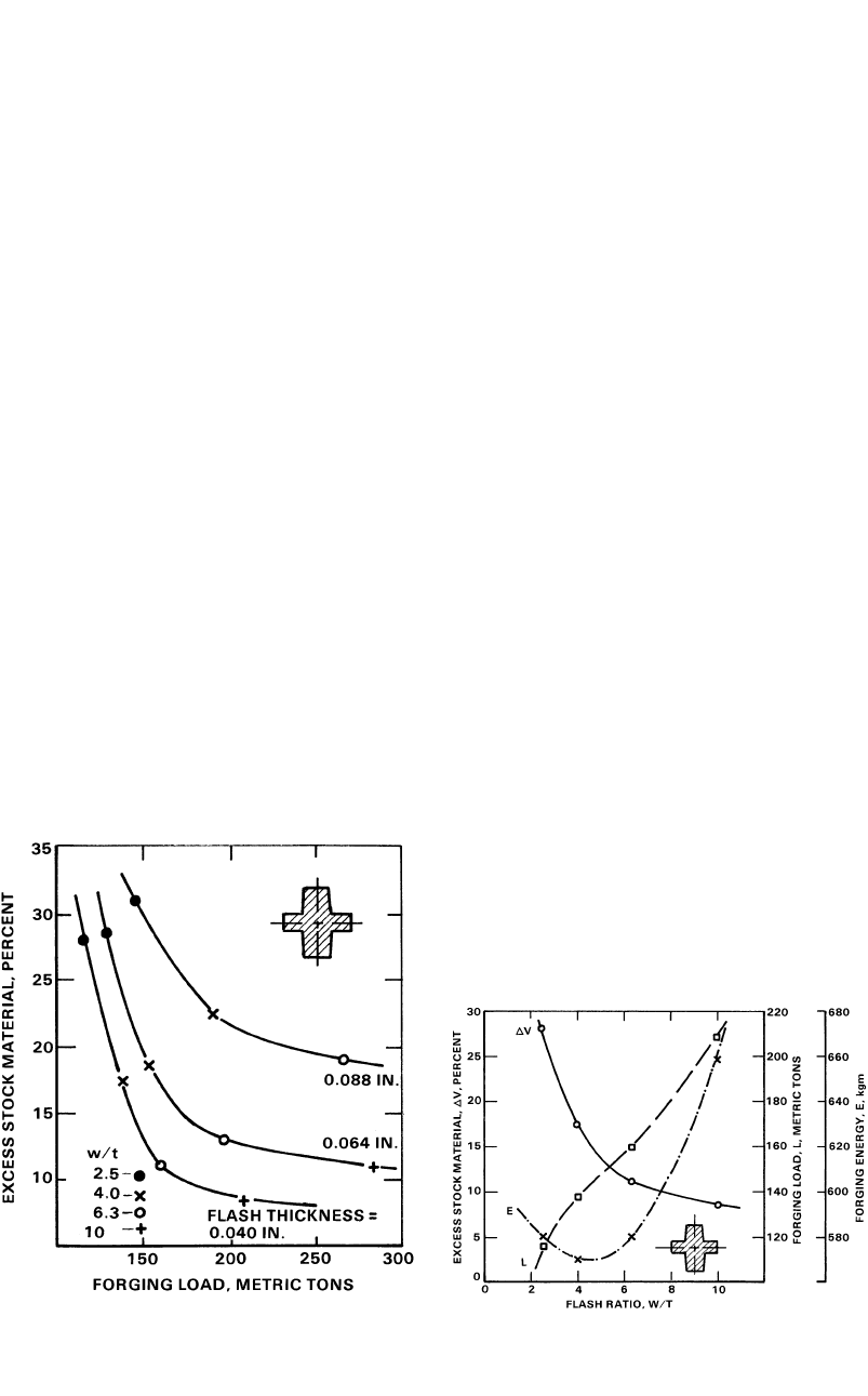
Fig. 14.12
Relationships among flash width/thickness ratio,
excess stock material, forging load, and energy
for a constant flash thickness, t, of 0.04 in. (1.0 mm) (same forging
as that shown in Fig. 14.11) [Vieregge, 1968]
Fig. 14.11
Relationships among excess stock material, flash
thickness, flash width/thickness ratio, and forg-
ing load for mechanical press forging of a round part approxi-
mately 3 in. (7.6 cm) in diameter by 3.5 in. (8.9 cm) high [Vi-
eregge, 1968]
tire cavity, and the forging should be completed.
However, P
3
represents the final load reached in
normal practice for ensuring that the cavity is
completely filled and that the forging has the
proper dimensions. During the stroke from P
2
to
P
3
, all the metal flow occurs near or in the flash
gap, which in turn becomes more restrictive as
the dies close. In that respect, the detail most
difficult to fill determines the minimum load for
producing a fully filled forging. Thus, the di-
mensions of the flash determine the final load
required for closing the dies. Formation of the
flash, however, is greatly influenced by the
amount of excess material available in the cav-
ity, because that amount determines the instan-
taneous height of the extruded flash and, there-
fore, the die stresses.
The effect of excess metal volume in flash
formation was studied extensively [Vieregge,
1968]. It was found that a cavity can be filled
with various flash geometries provided that there
is always a sufficient supply of material in the
die. Thus, it is possible to fill the same cavity by
using a less restrictive, i.e., thicker, flash and to
do this at a lower total forging load if the nec-
essary excess material is available (in this case,
the advantages of lower forging load and lower
cavity stress are offset by increased scrap loss)
or if the workpiece is properly preformed (in
which case low stresses and material losses are
obtained by extra preforming). These relation-
ships are illustrated in Fig. 14.11 and 14.12.
14.4.2 Empirical Methods for
Flash Design
The “shape classification” (Fig. 14.8) has
been utilized in systematic evaluation of flash
dimensions in steel forgings. For this purpose,
1500 forgings from eight different forging com-
panies were classified into shape groups, as
shown in Fig. 14.8. By evaluating the flash de-
signs suggested for these forgings, an attempt
was made to establish a relationship between
forging weight and flash dimensions. The results
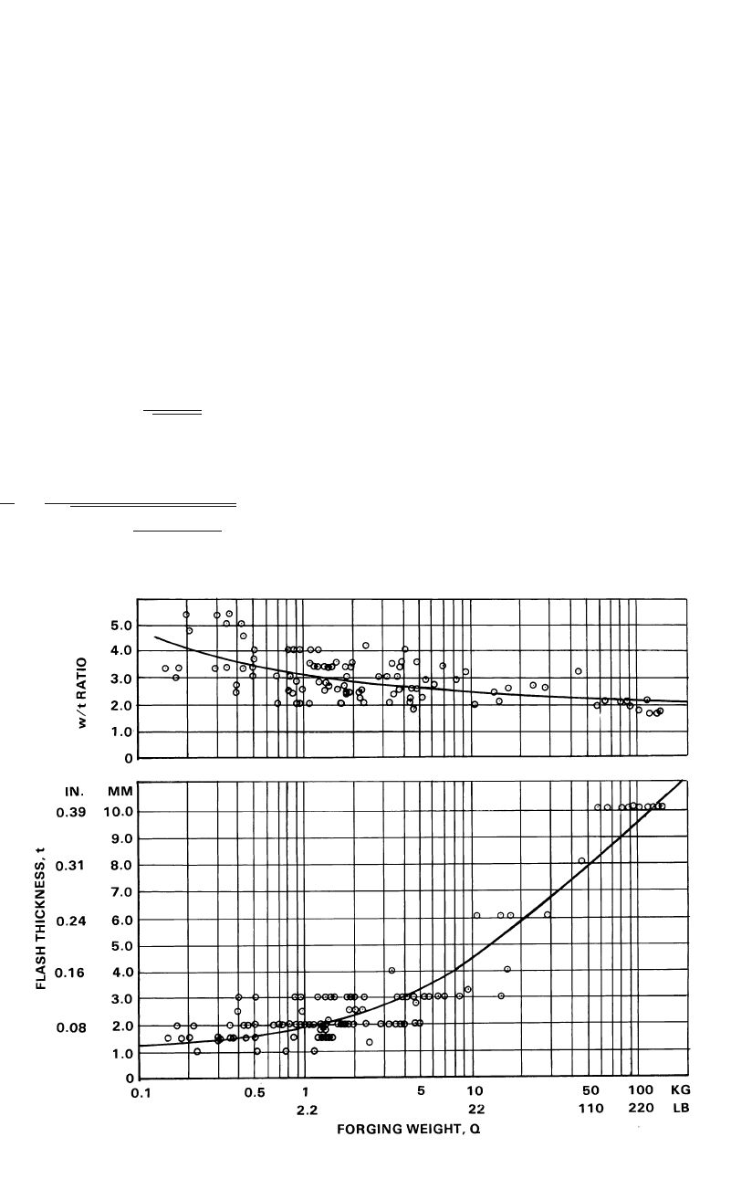
for group 224 are presented in Fig. 14.13 as an
example [Altan et al., 1973]. This figure can be
used for selecting the flash thickness based on
the forging weight, Q, of the forging. This graph
also shows the relationship between the flash
width/thickness (w/t) ratio and the forging
weight. Thus, knowing the weight of the part to
be forged, it is possible to find the corresponding
flash thickness and w/t ratio. Thus, the user can
obtain the flash dimensions based on the weight
of the forging.
There is no unique choice of the flash dimen-
sions for a forging operation. The choice is vari-
able within a range of values where the flash
allowance and the forging load are not too high.
There has to be a compromise between the two.
In general, the flash thickness is shown to in-
crease with increasing forging weight, while the
ratio of flash width to flash thickness (w/t) de-
creases to a limiting value. In order to investi-
Process Design in Impression-Die Forging / 169
Fig. 14.13
Variations in flash-land-to-thickness ratio and in flash thickness, t, with weight, Q, of forgings of group 224 (materials:
carbon and alloy steels)
gate the effect of forging shape on flash dimen-
sions, other subgroups were studied, and it was
concluded that the influence of shape is not as
significant as that of forging weight [Altan et al.,
1973].
It is also possible to determine the flash di-
mensions for round forgings, using the billet di-
mensions. Thus, it is possible to obtain little
flash allowance and minimize the forging en-
ergy. For round forgings, Eq 14.6 and 14.7 pre-
dict the flash dimensions that are a good com-
promise between the flash allowance and the
forging load [Vieregge, 1968]:
1
t ⳱ [0.017 • D] Ⳮ (Eq 14.6)
冤冥
D Ⳮ 5
冪
W30
⳱ (Eq 14.7)
2
t
2 • D
3D1Ⳮ
冤冢 冣冥
冪
H(2R Ⳮ D)
h
where w is the flash width (mm), t is the flash
thickness (mm), H is the height of the ribs or
shaft (mm), D is the outside diameter of the forg-
ing (mm), and R
h
is the radial distance of the
center of a rib from the axis of symmetry of the
forging.
14.5 Prediction of
Forging Stresses and Loads
Prediction of forging load and pressure in
closed- and impression-die forging operations is
difficult. Most forging operations are of non-
steady-state type in terms of metal flow, stresses,
and temperatures, i.e. all these variables vary
continuously during the process. In addition,
forgings comprise an enormously large number
of geometrical shapes and materials, which re-
quire different, even though similar, techniques
of engineering analysis. Because of these diffi-
culties encountered in practice, forging loads are
usually estimated on the basis of empirical pro-
cedures using empirically developed formulae.
170 / Cold and Hot Forging: Fundamentals and Applications
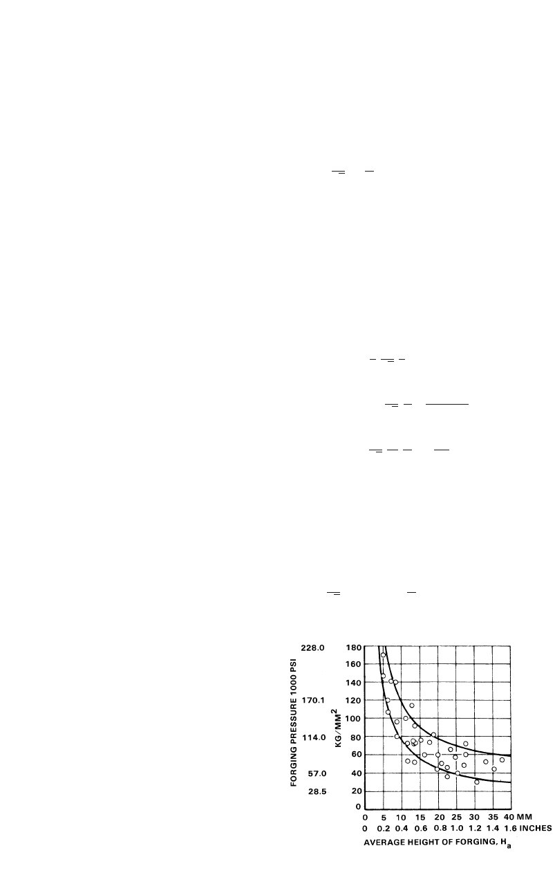
Fig. 14.14
Forging pressure versus average forging height
(H
a
) for forging of carbon and low-alloy steels at
flash ratios, w/t, from 2 to 4 [Neuberger et al., 1962]
14.5.1 Empirical Methods for Estimation
of Forging Pressure and Load
In estimating the forging load empirically, the
surface area of the forging, including the flash
zone, is multiplied by an average forging pres-
sure known from experience. The forging pres-
sures encountered in practice vary from 20 to 70
tons/in.
2
depending on the material and the ge-
ometry of the part. Neuberger and Pannasch
[Neuberger et al., 1962] conducted forging ex-
periments with various carbon steels (up to
0.6% C) and with low-alloy steels using flash
ratios, w/t (where w is flash-land width and t is
the flash thickness), from 2 to 4 (Fig. 14.14).
They found that the variable that most influences
the forging pressure, P
a
, is the average height,
H
a
, of the forging. The lower curve relates to
relatively simple parts, whereas the upper curve
to slightly difficult ones [Neuberger et al., 1962].
Most empirical methods, summarized in
terms of simple formulae or nomograms, are not
sufficiently general to predict forging loads for
a variety of parts and materials. Lacking a suit-
able empirical formula, one may use suitable an-
alytical techniques of varying degrees of com-
plexity for calculating forging load and stresses.
Among these techniques, the relatively simple
slab method has been proven to be very practical
for predicting forging loads.
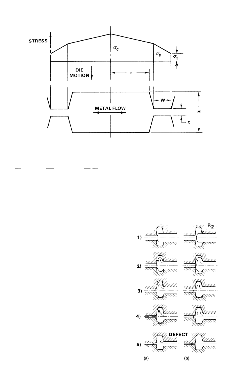
14.5.2 Simplified Slab
Method to Estimate Forging Load
The slab method has been successfully used
for predicting forging loads and stresses with ac-
ceptable engineering accuracy. For this purpose,
a forging is divided into various plane strain and
axisymmetric sections, and then simplified
equations are used to predict the average pres-
sure and load for each section before all these
load components are added together. This
method used in the practical prediction of forg-
ing loads is shown in Fig. 14.15 [Subramanian
et al., 1980]. In this analysis, it is assumed that
the cavity has a rectangular shape and the flash
geometry illustrated in Fig. 14.15. In actual
practice, where the cavity is not rectangular, the
cross section is simplified to conform to this
model.
As seen in Fig. 14.15, the cavity height is de-
noted by H, the radius (or half width of the cav-
ity) by r, the flash thickness by t, and the flash
width by w. The stresses at various locations of
the cross section and hence the load acting on
the cross section can be estimated as follows.
With the flow stress in the flash region de-
noted by r
f
and the frictional shear factor by m,
the stress at the entrance from the cavity into the
flash of an axisymmetric cross section, r
ea
,is
given by:
2w
r ⳱ m Ⳮ 1 r (Eq 14.8)
ea f
冢冣
t
3
冪
Because of rapid chilling and a high defor-
mation rate, the flow stress in the flash region is
considered to be different from the flow stress
in the cavity. Hence, two different flow stresses
are used for the flash and cavity regions. The
total load (P
ta
) on the cross section is the sum-
mation of the load acting on the flash region and
the load acting on the die cavity:
2m1
33
P ⳱ 2pr ⳮ (R ⳮ r)
ta f
冤
3t
3
冪
22
mR R ⳮ r
Ⳮ 1 Ⳮ 2
冢冣冢冣冥
t2
3
冪
m r r r
cea
2
Ⳮ 2pr Ⳮ (Eq 14.9)
冤冥
3H 2
3
冪
where R ⳱ r Ⳮ w, r
f
is the flow stress in the
flash region, and r
c
is the flow stress in the cav-
ity.
For the plane-strain cross sections, the equa-
tions corresponding to Eq 14.8 and 14.9 are:
2w
r ⳱ r 1 Ⳮ m (Eq 14.10)
ep f
冢冣
t
3
冪
Process Design in Impression-Die Forging / 171
Fig. 14.16
Defect formation in forging when fillet radii are
too small [Haller, 1971]
2mw Lm
P ⳱ wr 2 ⳭⳭr Ⳮ r L
tp f ep c
冢冣冢 冣
t2H
33
冪冪
(Eq 14.11)
where L is the cavity width, i.e., L ⳱ 2r in Fig.
14.15. The above equations are relatively simple
and can be programmed for practical use. The
following information is required to perform
these calculations:
●
The geometry of the part
●
The flow stresses in the cavity and the flash
during the final stages of the forging opera-
tion
●
The friction at the die/forging interface
Appendix A gives an example of estimation
of the load required for forging connecting rods.
A comparison between the theoretical prediction
and the actual data from forging trials is also
provided.
14.6 Design of
Blocker (Preform) Dies
One of the most important aspects of closed-
die forging is the design of preforms or blockers
to achieve adequate metal distribution [Altan et
al., 1973]. Thus, in the finish forging operation,
defect-free metal flow and complete die filling
can be achieved, and metal losses into the flash
can be minimized. In preforming, round or
round-cornered square stock with constant cross
section is deformed in such a manner that a de-
sired volume distribution is achieved prior to im-
pression-die forging. In blocking, the preform is
forged in a blocker cavity prior to finish forging.
The determination of the preform configura-
tion is an especially difficult task and an art in
itself, requiring skills achieved only by years of
extensive experience. Designing a correct pre-
Fig. 14.15 Schematic of a simple closed-die forging and forging stress distribution [Subramanian et al., 1980]