Cold and Hot Forging: Fundamentals and Applications / Edited by Taylan Altan, Gracious Ngaile, Gangshu Shen
Подождите немного. Документ загружается.

CHAPTER 12
Special Machines for Forging
Pinak Barve
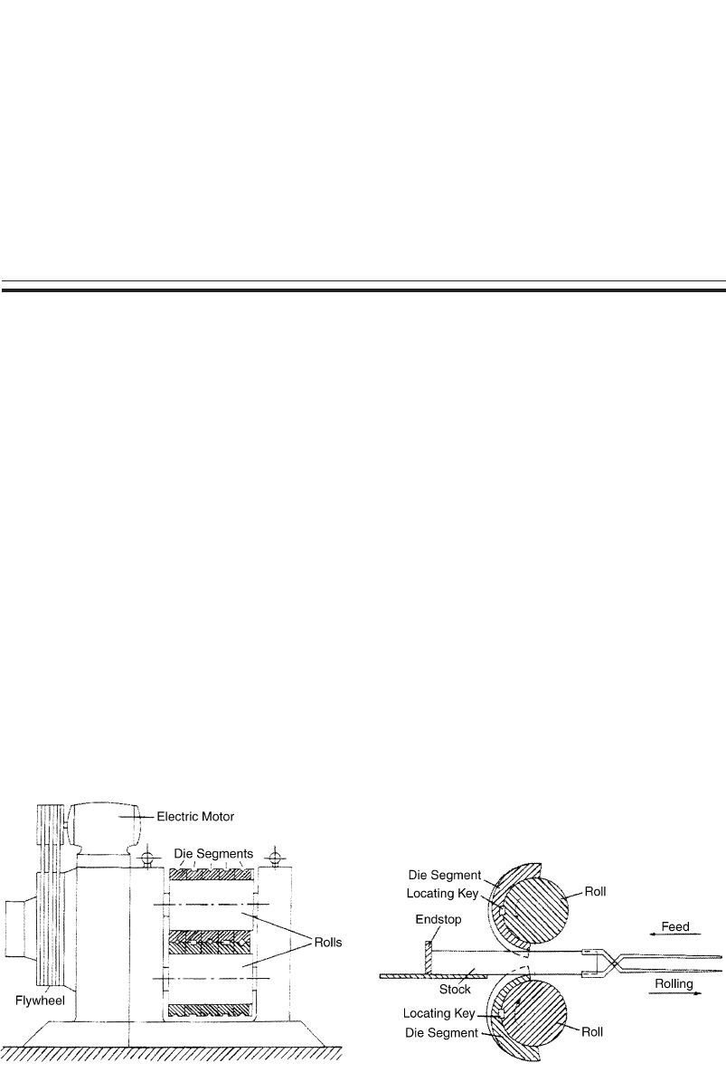
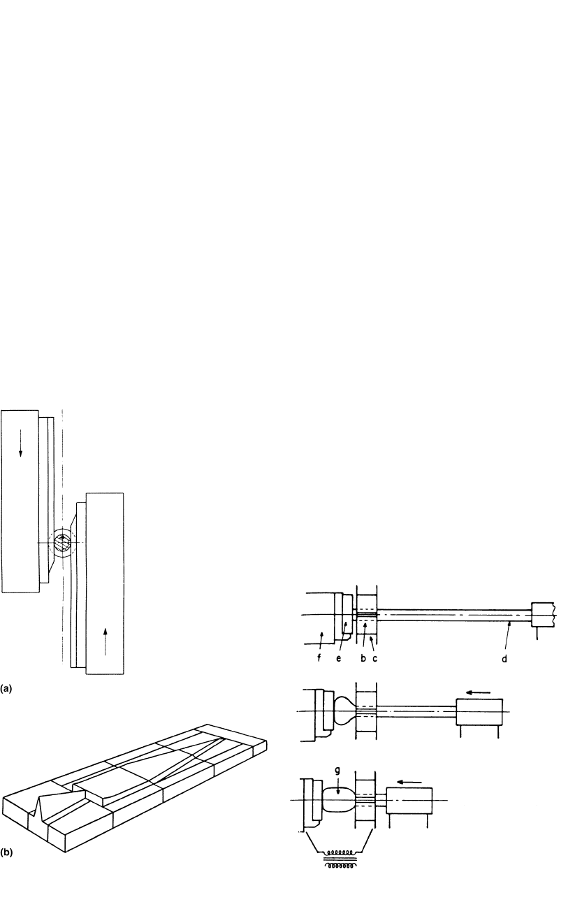
Fig. 12.2 Schematic of the reducer rolling operationFig. 12.1 Schematic of forging rolls for reducer rolling
12.1 Introduction
Prior to forging in an impression die, billet
stock must be often preformed to achieve ade-
quate material distribution, especially in hot
forging with flash. Several special machines are
used for the purpose of preforming the incoming
stock. Some of these machines may also be used
for finish forging.
The principle of forging rolls, or reducer rolls,
is illustrated schematically in Fig. 12.1. This ma-
chine is generally used for volume distribution
in long and thin parts, prior to closed-die forg-
ing. A typical operation on reducer rolls, such
as those of Fig. 12.2, is as follows.
The operator or a robot places the heated
stock on a table in the front of the machine,
grasps the stock with the tongs, and starts the
machine with a foot pedal or automatic signal.
During the portion of the roll rotation, when the
rolls are in open position, the stock is placed
between the rolls against a stock gage and in line
with the first roll groove. As the rolls rotate,
forging begins and the deformed stock is forced
toward the front of the machine [Altan et al.,
1973].
These sequences are repeated for the next
grooves. Thus, the shape of the die segments on
the forging rolls determines the rolled configu-
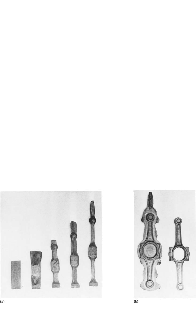
ration. An example illustrating the application
of preforming by roll forging, or reducer rolling,
is shown in Fig. 12.3. Another example, illus-
trating preforming for a truck axle forging, is
seen in Fig. 12.4.
In roll forging, the contact time between the
workpiece and the roll segments is extremely
short due to the high speed of the rolls. There-
fore, even after the final rolling operation, the
workpiece is still hot and can be finish forged
under a hammer or press without reheating.
For high-volume production, the reducer roll-
ing operation is automated. The stock is gripped,
fed into the rolls, transferred from one die seg-
ment to the other, and released on a conveyor
using a dedicated robot. In producing long parts,
Cold and Hot Forging Fundamentals and Applications
Taylan Altan, Gracious Ngaile, Gangshu Shen, editors, p141-150
DOI:10.1361/chff2005p141
Copyright © 2005 ASM International®
All rights reserved.
www.asminternational.org
142 / Cold and Hot Forging: Fundamentals and Applications
Fig. 12.3
Example of preforming by reducer rolling in forging of connecting rods. (a) Preforms prepared in reducer rolls. (b) Finish
forging before and after trimming. [Altan et al., 1973]
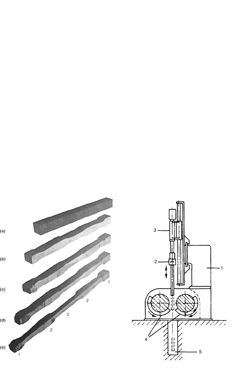
such as crankshafts and front axles, it is possible
to use vertical reducer rollers, as seen in Fig.
12.5.
The design of the roll segments needs consid-
erable experience. Recently, three-dimensional
FEM codes have been used to (a) simulate the
reducer rolling operation and (b) design and op-
timize the configuration of the die segments.
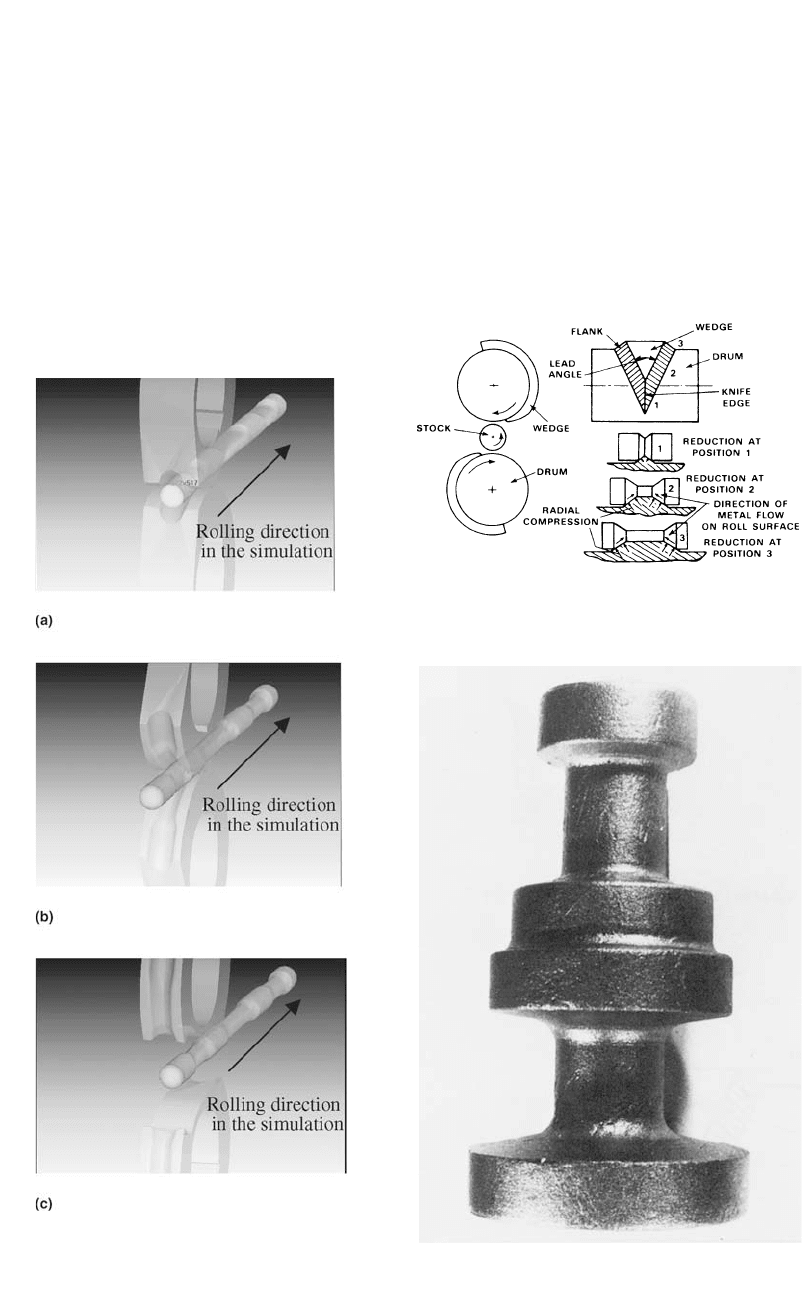
Figure 12.6 shows, as an example, two roll
passes, simulated by the commercial software
DEFORM 3-D [SFTC, 2003]. The desired shape
is produced by rolling the heated billet between
two rotating dies having appropriately profiled
grooves. After the first pass, the billet is fed into
the roll segments of the second pass after 90⬚
rotation.
12.2 Transverse or
Cross-Rolling Machines
Transverse rolling is used for producing pre-
forms or finish forgings from round billets. As
seen in Fig 12.7, a round billet is inserted trans-
versely between two or three rolls, which rotate
in the same direction and drive the billet [Altan
et al., 1973]. The rolls, which hold replaceable
die segments with appropriate impressions,
make one revolution while the workpiece rotates
several times in the opposite direction. Thus, the
transverse rolling method can form axially sym-
metrical shafts with complex geometry in one
operation. As an example, a forging produced
by this method is shown in Fig. 12.8. The trans-
verse rolling machines are suitable for automatic
production, using bar stock automatically fed to
the rolls through an induction heating unit.
There are two main types of transverse rolling
machines:
●
The two- or-three-roll machine, (Fig. 12.7)
●
A transverse rolling machine that uses two
straight wedge-shaped tools (Fig. 12.9)
12.3 Electric Upsetters
Electric upsetters are used mostly in preform
preparation for gathering a large amount of ma-
terial at one end of a round bar. The principle of
operation is illustrated in Fig. 12.10. A bar of
circular cross section (d) is gripped between the
tools (b) of the electrode (c) and is pushed by
the hydraulically or pneumatically operated up-
setting head against the anvil plate (f) on which
the other electrode (e) is secured. On switching
on the current, the rod section contained be-
tween the electrodes heats rapidly and the for-
mation of the head begins. The cold bar is con-
Special Machines for Forging / 143
tinuously fed between the gripping electrodes
(b), thus the metal accumulates continuously in
the head. The anvil electrode is gradually re-
tracted to give enough space for the formation
of the head. As soon as sufficient quantity of
metal is gathered, the machine switches off and
the product can be removed by its cold end. Nor-
mally, the head is formed to final shape in a me-
chanical or screw-type press in the same heat.
Thus, the process is suitable for manufacturing
components such as automotive exhaust valves,
or steam turbine blades [Altan et al., 1973].
The flat anvil electrode can be replaced by a
water-cooled copper mold into which material is
gathered and formed to close shape and dimen-
sions. Material can be gathered at any point on
the length of the bar by placing a sheath around
one end. The only limitation on size is the avail-
ability of electric current. Commercially avail-
able equipment is capable of upsetting 0.5 to 5
in. (12.5 to 125 mm) diameter bars. As time for
upsetting a head of average size is 2 to 5 min,
several units are required for achieving high vol-
ume production.
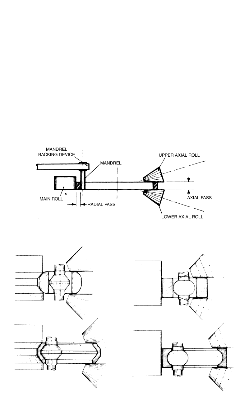
12.4 Ring-Rolling Mills
The principle of operation of a horizontal
ring-rolling mill is illustrated in Fig. 12.11. The
vertical mills operate essentially in the same
way. The doughnut-shaped blank is placed over
a mandrel with a diameter smaller than the in-
side diameter of the blank. The mandrel, in mov-
ing laterally toward the main roll, applies pres-
sure on the blank. The main roll, which is driven,
rotates the blank and the mandrel as the cross
section of the blank is reduced. The axial rolls
provide support to the deforming ring and con-
trol its width and its squareness. As seen in Fig.
12.12, by modifying the configurations of the
mandrel and the main roll, it is possible to roll
rings with internal and external profiles [Beseler,
1969].
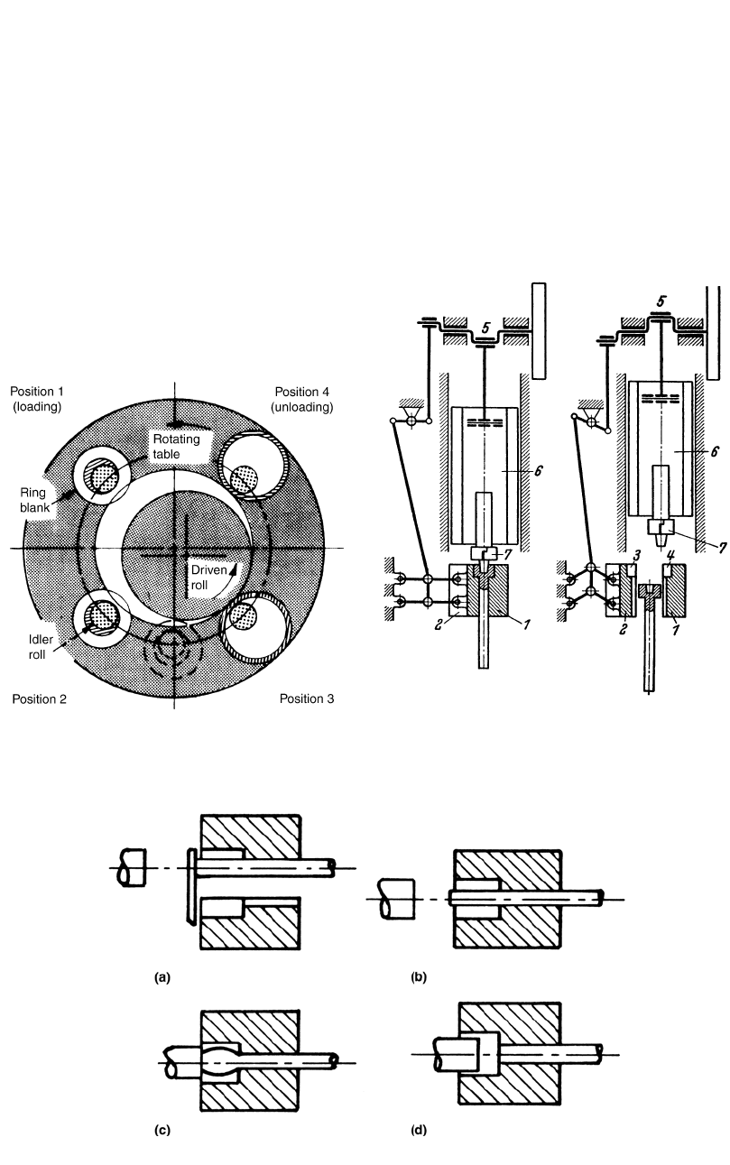
For components required in large quantities,
such as bearing races, completely automated
ring-rolling installations are available. Such an
installation may consist of a billet shear, a heat-
ing furnace, a forging press, and a ring-rolling
mill. The principles of an automatic horizontal
ring-rolling mill for manufacturing bearing races
Fig. 12.5
Schematic of a vertical reducer roller. 1, roll stand;
2, holder on manipulator; 3, slide; 4, rolls; 5, part
transfer conveyor. [Haller, 1982]
Fig. 12.4
Deformation stages in reducer rolling of a forging
to produce a truck axle. (a) Starting billet. (b)–(e)
Several reducer roll passes. (1)–(3) Locations where more mate-
rial needed in the final forging. [Haller, 1982]
144 / Cold and Hot Forging: Fundamentals and Applications
Fig. 12.8
Forging produced in a transverse rolling machine.
[Neuberger et al., 1968]
are illustrated in Fig. 12.13. Four mandrels are
mounted in a rotating table, and the main roll,
eccentrically located within the table, is driven
independently by a variable-speed drive. The
blank placed over the mandrel, in position 1, is
rolled out into a ring as the clearance between
mandrel and main roll decreases. After having
passed the rolling zone, the hinged table seg-
ment is lifted by a cam operation, and the fin-
ished ring is discharged from the machine.
12.5 Horizontal Forging
Machines or Upsetters
The horizontal forging machines are essen-
tially horizontal mechanical presses. As seen in
Fig. 12.14, these machines employ two gripper
dies, one stationary and the other movable. The
dies are closed side-to-side by a toggle mecha-
Fig. 12.7
Principle of operation of transverse rolling ma-
chines. [Neuberger et al., 1968]
Fig. 12.6
Computer simulation of reducer rolling operation
using DEFORM—3D (only two passes are shown).
(a) First pass. (b) Second pass after rotating 90⬚. (c) At the end of
the second pass. [SFTC, 2003]
Special Machines for Forging / 145
Fig. 12.10
Principle of operation of the electric upsetter.
See text for details. [Altan et al., 1973]
nism operated by a cam or eccentric located on
the eccentric shaft. Several matching die inserts
are placed in the gripper dies, while the slide
carrying the punches is moved by an eccentric-
pitman mechanism. The operational sequence of
a horizontal forging machine is illustrated in Fig.
12.15 for the upsetting process: (a) the hot end
of the bar is placed into the stationary gripper
die against a stop, (b) the moving gripper die
closes and the stop retracts, (c) the heading tool
begins to deform the bar, and (d) completes the
upsetting at the end of its stroke.
The upsetters are used for upset forging,
piercing, and reducing of bars and tubes. In au-
tomatic operation, the parts are transported by
finger-type cam-operated devices or walking-
beam-type transfer devices from one die cavity
to the next. Most horizontal forging machines
are designed such that the gripper dies are ori-
ented vertically, i.e., during closing action, the
movable gripping die moves horizontally
[Lange, 1958].
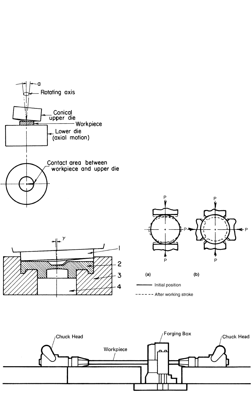
12.6 Rotary or
Orbital Forging Machines
The principles of rotary forging machines are
illustrated in Fig. 12.16 for a simple upsetting
operation.
Instead of the direct pressing action between
two flat platens, the workpiece is subjected to a
combined rolling and pressing action between a
flat bottom platen and a swiveling upper die with
a conical working face. The cone axis is inclined
so that the narrow sector in contact with the
workpiece is parallel to the lower platen. As the
cone rotates about the cone apex, the contact
zone also rotates. At the same time, the platens
are pressed toward each other so that the work-
piece is progressively compressed by the rolling
action. Press loading is appreciably less than that
of conventional upsetting because of relatively
small area of instantaneous contact. The appli-
cation of a rotary forging machine to a closed-
die forging operation is illustrated in Fig. 12.17.
12.7 Radial Forging Machines
In many applications, it is necessary to forge,
as final product or as a preforming step, solid
Fig. 12.9
Principles of and tooling for transverse rolling ma-
chine with straight dies. (a) Operation. (b) Assem-
bly of simple die. [Altan et al., 1973]
146 / Cold and Hot Forging: Fundamentals and Applications
Fig. 12.12 Horizontal ring-rolling mill for producing rings with internal and external profiles. [Beseler, 1969]
Fig. 12.11 Operational principles of a horizontal ring-rolling mill. [Beseler, 1969]
shafts with varying or constant diameter along
the length and tubes with internal or external
varying diameter. All these parts require sym-
metrical reduction of cross sections. For some
of these applications, open-die forging presses
cannot be used economically because they are
limited in number of strokes per minute and in
the speed of feed and manipulation of the stock
during forging. In addition, large reductions be-
tween two flat dies may cause excessive chilling
at the billet corners and cracking at the center of
the billet. Although these latter problems may
be reduced by using V-dies, each V-die set can
be used only for a certain dimension range and
frequent die changes during forging increase the
production costs. Figure 12.18 indicates that the
best solution for high-production symmetrical
reduction of cross sections is a forging system
that squeezes the material from all sizes simul-
taneously. There are several machine types de-
signed specifically for this purpose of radial or
draw-forging of axisymmetric parts [Haller,
1971].
Automated and computer-numerical-con-
trolled (CNC) radial forging machines can be
used for hot or cold forging, with two, three, or
four dies to produce solid or hollow, round,
square, rectangular, or profiled sections. Some
of the principal applications are production of
stepped shafts or tubes, sizing of solid bars such
Special Machines for Forging / 147
Fig. 12.14
Schematic of a horizontal forging machine. 1,
stationary gripping die; 2, movable gripping die;
3 and 4, end-die cavities; 5, eccentric shaft; 6, slide carrying the
punches; 7, upsetting and piercing punch. [Lange, 1958]
Fig. 12.13
Principle of semiautomatic ring-rolling machine
for manufacturing of bearing races. [Beseler,
1969]
as pilger mandrels, and sizing of the bores of
tubes to exact round or profiled shapes. The tol-
erances in hot forged tubes are about Ⳳ0.004 in.
(Ⳳ0.1 mm) on the inside diameter (ID). In cold
forging the outside diameter (OD) and ID tol-
erances are about Ⳳ0.004 (Ⳳ0.1 mm) and
Ⳳ0.001 in. (0.025 mm), respectively [Walter,
1965].
There are two types of radial precision forging
machines: vertical and horizontal. Both models
use essentially the same design principles. The
vertical models are suitable only for relatively
short components and are difficult to automate.
The horizontal models are built in several vari-
ations depending on the application. The hori-
zontal machines consist of a forging box with
gear drive, one or two chuck heads to manipu-
late the workpiece, centering devices, and nec-
essary hydraulic and electronic control compo-
nents (Fig. 12.19). The core of the machine is a
robust cast steel forging box that absorbs all
Fig. 12.15 Operating sequence in upsetting on a horizontal forging machine
148 / Cold and Hot Forging: Fundamentals and Applications
Fig. 12.16
Principle of rotary or orbital forging machines.
[Altan et al., 1973]
Fig. 12.17
Illustration of closed-die forging with a rotary
forging machine. 1, rotating upper platen; 2,
workpiece; 3, lower die; 4, ejector
Fig. 12.18
Deformation of a round cross section in stretch
forging. P, load. (a) Between flat anvils. (b) Be-
tween four curves of a radial forging machine. [Haller, 1971]
forging forces (Fig. 12.20). It is mounted with
the gear box in a support bolted to the founda-
tion frame. The forging box contains four rotat-
able adjustment housings in which the eccentric
shafts are mounted. The eccentric shafts, which
are driven by an electric motor through a gear
system, actuate the connecting rods and the forg-
ing dies at a rate of 250 to 1800 strokes/min.
The stroke position of the connecting rods (or
dies) is adjusted in pairs independently (for rec-
tangles or special shapes) or in unison (for
rounds and squares) by rotating each adjustment
housing through a link, screw, adjustment nut,
and worm gear drive powered by one or two
hydraulic motors. Each adjustment nut rests,
through a piston, on an oil cushion of a hydraulic
cylinder. During operation, the forging pressure
generates in this oil cushion a pressure propor-
tional (about 20%) to the forging pressure. The
pressure in this oil cushion is continuously
monitored, and if it exceeds a certain limit the
adjustment housings are immediately rotated to
bring the dies to open position while the move-
ment of the chuck heads is stopped simulta-
neously. This system protects the machine from
overloading [Altan et al., 1973].
Depending on the machine type, one or two
hydraulically driven chuck heads are provided
Fig. 12.19 Schematic of a GFM radial precision forging machine with two chuck heads. [Walter, 1965]
Special Machines for Forging / 149
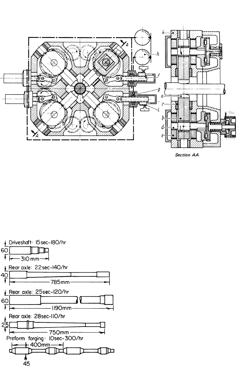
Fig. 12.20
Forging box of a radial precision forging machine illustrating the tool function and adjustment. (a) Dies. (b) Pitman arm.
(c) Guides. (d) Eccentric shaft. (e) Adjustment housing. (f) Adjustment screw. (g) Worm gear drive. (h) Adjustment input.
(i) Adjustable cam. (k) Forging box. [Altan et al., 1973]
Fig. 12.21
Typical examples of stepped shafts produced in
precision radial forging machines. [Altan et al.,
1973]
for holding and manipulating the workpiece dur-
ing forging. Two chuck heads are used when the
workpiece must be forged over its entire length,
including the chucked ends, in one heat. During
forging, round components are rotated while
square, rectangular, and profiled sections are
forged at fixed positions. The movement of the
chuck heads and the variation of the forging
stroke in forging stepped components can be
controlled by numerical control. For the forging
of tubular parts, the chuck heads are provided
with stationary or movable mandrels, which are
cooled internally in hot forging applications.
Central water cooling and lubrication of critical
machine components are carried out automati-
cally during the operation of the machine. The
radial precision forging machines are capable of
producing parts similar to those shown in Fig.
12.21.
REFERENCES
[Altan et al., 1973]: Altan, T., Boulger, F.W.,
Becker, J.R., Akgermon, N., Henning, H.J.,
“Forging Equipment, Materials, and Prac-
tices,” Metals and Ceramics Information Cen-
ter, Battelle Columbus Laboratories, 1973.
[Beseler, 1969]: Beseler, K.H., “Modern Ring-
Rolling Practice,” Met. Form., Vol 36, Feb
1969, p 1.
[Haller, 1971]: Haller, H.W., Handbook of Forg-
ing (in German), Hanser Verlag, 1971.
[Haller, 1982]: Haller, H.W., Practice of Im-
pression Die Forging (in German), Hanser
Verlag, 1982.

150 / Cold and Hot Forging: Fundamentals and Applications
[Lange, 1958]: Lange, K., Closed-Die Forging
of Steel (in German), Springer-Verlag, Berlin,
1958.
[Neuberger et al., 1968]: Neuberger, F., et al.,
“Transverse Rolling,” Met. Form., Vol 35, Oct
1968, p 1.
[SFTC, 2003]: Scientific Forming Technologies
Corp., DEFORM 2D and 3D Software, Co-
lumbus, OH, 2003.
[Walter, 1965]: Walter, L., “Use of Precision
Forging Machines,” Met. Treat., Aug 1965, p
296.