Cold and Hot Forging: Fundamentals and Applications / Edited by Taylan Altan, Gracious Ngaile, Gangshu Shen
Подождите немного. Документ загружается.


120 / Cold and Hot Forging: Fundamentals and Applications
Fig. 11.6
Full-stroke parallelism control of the press slide.
[Schuler Handbook, 1998]
control systems act in the die mounting area to
counter slide tilt. Position measurement sensors
monitor the position of the slide and activate the
parallelism control system (Fig. 11.5). The par-
allelism controlling cylinders act on the corners
of the slide plate, and they are pushed during the
forming process against a centrally applied pres-
sure. If the electronic parallelism monitor sensor
detects a position error, the pressure on the lead-
ing side is increased by means of servo valves,
and at the same time reduced on the opposite
side to the same degree. The sum of exerted par-
allelism control forces remains constant, and the
slide tilt balance is restored. Depending on the
deformation speed, a slide parallelism of 0.05 to
0.2 mm/m is achieved. A central device adjusts
the system to different die heights by means of
spindles at the slide.
Full-stroke parallelism control involves the
use of parallel control cylinders, with their pis-
tons permanently connected to the slide (Fig.
11.6). These act over the entire stroke of the
slide so that no setting spindles are required to
adjust the working stroke. Two cylinders with
the same surface area, arranged well outside the
center of the press, are subjected to a mean pres-
sure. The tensile and compressive forces are bal-
anced out by means of diagonal pipe connec-
tions. The system is neutral in terms of force
exerted on the slide. If an off-center load is ex-
erted by the die on the slide, a tilt moment is
generated. The slide position sensor detects a de-
viation from parallel and triggers the servo
valve. The valve increases the pressure on the
underside of the piston acting on the leading side
of the slide and thus also on the opposite upper
side of the piston. At the same time, the pressure
in the other connecting pipe is reduced. The op-
posing supporting torques exerted on the two
sides counteract the tilt moment.
11.2.3 Mechanical Crank and
Eccentric Presses
All mechanical presses employ flywheel en-
ergy, which is transferred to the workpiece by a
network of gears, cranks, eccentrics, or levers
(Fig. 11.7). The ability of mechanical presses to
deform the workpiece material is determined by
the length of the press stroke and the available
force at various stroke positions.
Two major groups of mechanical presses are:
●
Presses with crank drive
●
Presses with cam drive
Crank presses may have either simple or ex-
tended crank drives. Conventional crank presses
(the total stroke cannot be varied) and eccentric
presses (the total stroke is variable) belong to
the simple drives. If either a knuckle or a lever
is used to extend the crank drive, the designs are
called knuckle joint or link drive presses. Mul-
tipoint presses are those in which two or more
cranks are used to drive the same ram.
Other methods of classification are:
●
Frame type: C or closed frame
●
Number of useful motions: Single or more
●
Location of drive: Top drive (connecting rod
subjected to compression) and bottom drive
(connecting rod subjected to tension)
●
Position of drive shaft: Longitudinal or cross
shaft
●
Number of connecting rods: One-, two-, or
four-point drive
The drive system used in most mechanical
presses (crank or eccentric) is based on a slider-
crank mechanism that translates rotary motion
into reciprocating linear motion. The eccentric
Presses and Hammers for Cold and Hot Forging / 121
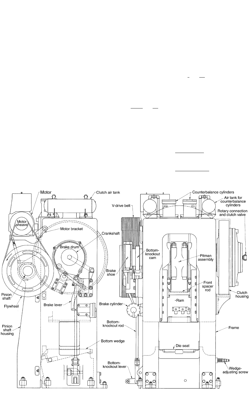
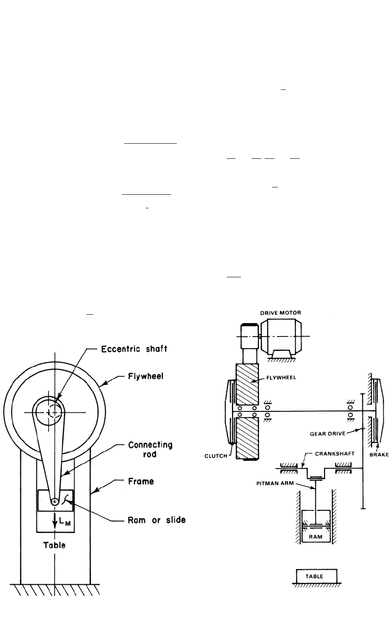
Fig. 11.7 Principal components of a mechanical forging press. [ASM Handbook, 1988]
shaft is connected through a clutch and brake
system directly to the flywheel (Fig. 11.8). In
designs for larger capacities, the flywheel is lo-
cated on the pinion shaft, which drives the ec-
centric shaft (Fig. 11.9). The constant clutch
torque, M, is available at the eccentric shaft,
which transmits the torque and the flywheel en-
ergy to the slide through the pitman arm or con-
necting rod, as illustrated in Fig. 11.8. The fly-
wheel, which is driven by an electric motor and
“V” belts, stores energy that is used only during
a small portion of the crank revolution, namely,
during deformation of the formed material.
Figure 11.10 shows the basic slider-crank
mechanism. The clutch at the flywheel transmits
the constant torque, M, to the eccentric (or
crank) shaft. The force diagram gives the rela-
tions between the torque, M, the force on the
connecting rod, P, and the tangential force, T:
T ⳱ P sin (␣ Ⳮ b) (Eq 11.1)
and
M ⳱ rT (Eq 11.2)
Usually, the ratio, k, of crank radius r to con-
necting-rod length l is small, about:
r1
k ⳱⳱
l10
or
sin b 1
⳱ (Eq 11.3)
sin ␣ 10
Using Eq 11.1 and considering that the total
press stroke is S ⳱ 2r, the machine load, L
M
,
acting on the ram is:
T cos b
L ⳱ P cos b ⳱
M
sin (␣ Ⳮ b)
2M cos b
⳱ (Eq 11.4)
S sin (␣ Ⳮ b)
122 / Cold and Hot Forging: Fundamentals and Applications
Fig. 11.8
Schematic of a mechanical press with eccentric
drive (clutch and brake on eccentric shaft). [Altan
et al., 1973]
Fig. 11.9
Schematic of a crank press with pinion-gear drive
(clutch and brake are on pinion shaft; for large ca-
pacities this design is more stable and provides high flywheel
energy). [Altan et al., 1983]
When the angles ␣ and b approach 0, i.e., toward
bottom dead center (BDC), L
M
may go to infin-
ity for constant torque, M. This is illustrated in
Fig. 11.11.
The stroke position, i.e., the distance, h, from
BDC, as a function of the crank angle, ␣, can be
derived from the geometric relationships illus-
trated in Fig. 11.10, to be:
222
h ⳱ (r Ⳮ 1) ⳮ (r cos ␣ Ⳮ l ⳮ r sin ␣)
冪
or
r
2
h ⳱ r(1 ⳮ cos ␣) Ⳮ l1ⳮ 1 ⳮ sin ␣
冢冢冣冣
冪
l
(Eq 11.5)
Using the binomial expansion, the term under
the square root sign can be approximated as 1 ⳮ
(r/l)
2
sin
2
␣/2.
Thus, Eq 11.5 can be transformed into:
2
r
2
h ⳱ r(1 ⳮ cos ␣) Ⳮ sin ␣ (Eq 11.6)
2l
For small values of ␣, i.e., near BDC, Eq 11.6
is approximated as:
S
h ⳱ r(1 ⳮ cos ␣) ⳱ (1 ⳮ cos ␣) (Eq 11.7)
2
The ram velocity, V, is obtained from Eq 11.6
by differentiation with respect to time, t:
dh dh d␣ dh
V ⳱⳱ ⳱ x
dt d␣ dt d␣
2
r
⳱ r sin ␣ Ⳮ sin ␣ cos ␣ x (Eq 11.8)
冢冣
l
where, with n being the rotational speed of the
crank in revolutions per minute, the angular ve-
locity x ⳱ 2pn/60 and the stroke S ⳱ 2r. Ne-
glecting the second small term in Eq 11.8 gives:
Spn
V ⳱ sin ␣ (Eq 11.9)
60
Presses and Hammers for Cold and Hot Forging / 123
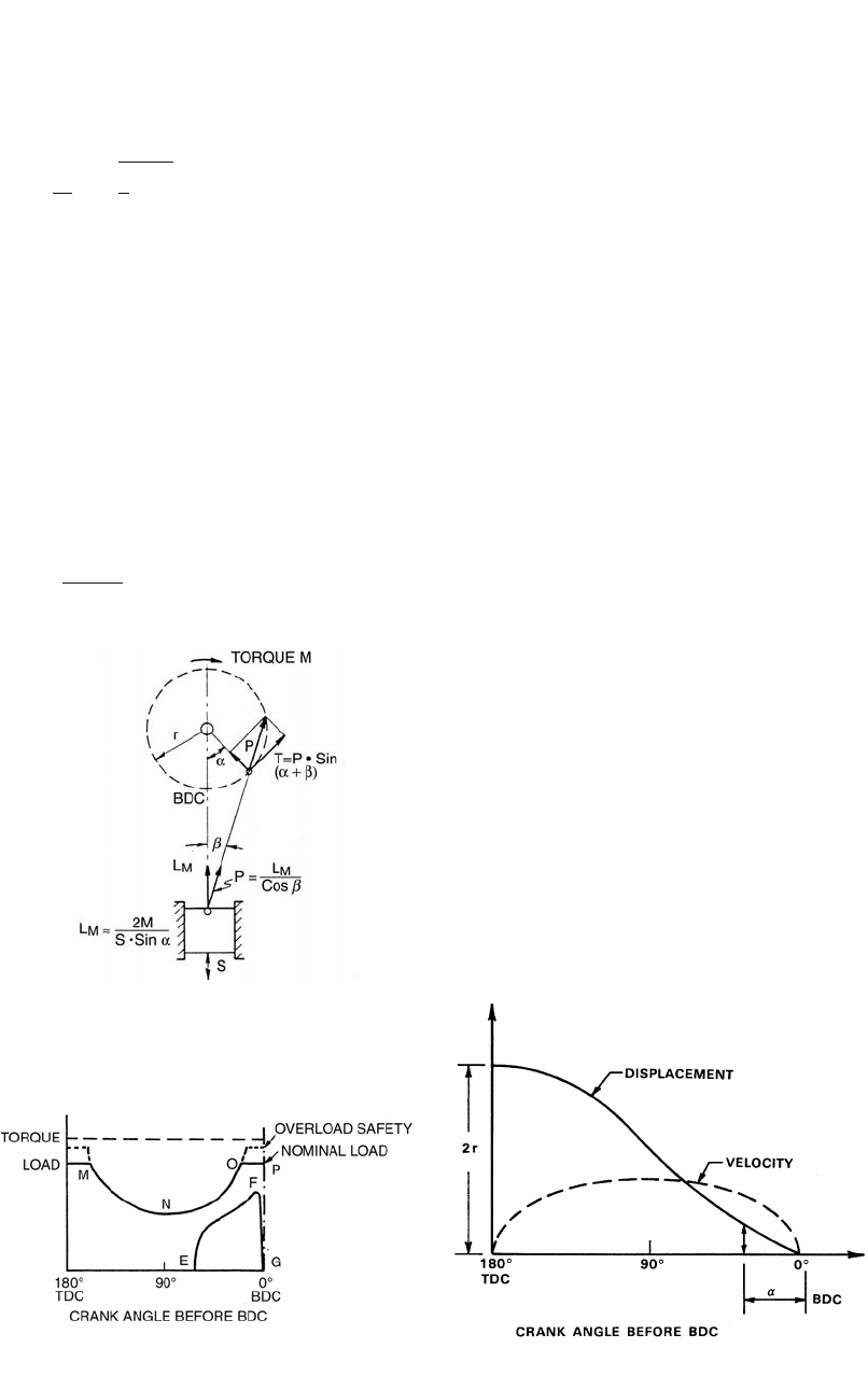
Fig. 11.12
Displacement and velocity in a simple slider-
crank mechanism (stroke ⳱ 2r)
Fig. 11.11
Variations of clutch torque and machine load
with crank angle in an eccentric or crank press.
[Altan et al., 1973]
Using the geometric relationships of Fig.
11.10, the ram velocity can be expressed as:
pnS
V ⳱ h ⳮ 1 (Eq 11.10)
冪
30 h
Thus with Eq 11.6 and 11.10 the displacement,
h, and the velocity, V, at each point of the ram
stroke can be calculated. Figure 11.12 illustrates
the variation of these values with the crank angle
␣ before BDC.
11.2.4 Load and Energy in
Mechanical Presses
With the symbols used in Fig. 11.10, Eq 11.4
gives the ram or machine load, L
M
. Considering
that angle b is much smaller than angle ␣,L
M
can be approximated as:
2M
L ⳱ (Eq 11.11)
M
S sin ␣
As shown in Fig. 11.11, Eq 11.11 illustrates
the variation of the slide load, L
M
, with the crank
angle, ␣, before bottom dead center, BDC, for
given values of torque, M, and stroke, S, of the
press. The torque, M, at the clutch has a constant
value for which the drive mechanism (i.e., ec-
centric shaft, pinion gear, clutch, brake, etc.) is
designed. Thus, from Eq 11.11 it can be seen
that, as the slide approaches the BDC, i.e., as
angle ␣ approaches zero, the available machine
load L
M
, may become infinitely large without
exceeding the constant clutch torque, M, i.e.,
without causing the friction clutch to slip.
From the observations made so far, the fol-
lowing conclusions may be drawn:
●
Crank and eccentric presses are displace-
ment-restricted machines. The slide velocity,
V, and the available slide load, L
M
, vary ac-
cording to the position of the slide before
BDC. Most manufacturers in the United
States rate their presses by specifying the
nominal load at
1
⁄
4
or
1
⁄
8
in. (6.4 or 3.2 mm)
before BDC. For different applications, the
nominal load may be specified at different
positions before BDC according to the stan-
dards established by the American Joint In-
dustry Conference.
●
If the load required by the forming process
is smaller than the load available at the press
(i.e., if curve EFG in Fig. 11.11 remains be-
low curve NOP), the process can be carried
out provided that the flywheel can supply the
necessary energy per stroke.
●
For small angles ␣ before BDC, within the
OP portion of curve NOP in Fig. 11.11, the
slide load, L
M
, can become larger than the
Fig. 11.10
The basic slider-crank mechanism used in crank
presses. S, stroke; BDC, bottom dead center; ␣,
crank angle before bottom dead center (BDC); L
M
, machine load.
[Altan et al., 1973]

124 / Cold and Hot Forging: Fundamentals and Applications
nominal press load if no overload safety (hy-
draulic or mechanical) is available on the
press. In this case, the press stalls, the fly-
wheel stops, and the entire flywheel energy
is transformed into deflection energy by
straining the press frame, the pitman arm,
and the drive mechanism. Usually, the press
can then be freed only by burning out the
tooling.
●
If the load curve EFG exceeds the press load
NOP (Fig. 11.11) before point O is reached,
then the friction clutch slides and the press
slide stops, but the flywheel continues to
turn. In this case, the press can be freed by
increasing the air pressure on the clutch and
by reversing the flywheel rotation if the slide
has stopped before BDC.
The energy needed for the forming operation
during each stroke is supplied by the flywheel,
which slows down to a permissible percent-
age—usually 10 to 20%—of its idle speed. The
total energy stored in a flywheel is:
2
2
Ix I pn
E ⳱⳱ (Eq 11.12)
FT
冢冣
2230
where I is the moment of inertia of the flywheel,
x is the angular velocity in radians per second,
and n is the rotational speed of the flywheel in
revolutions per minute. The total energy, E
S
,
used during one stroke is:
2
1Ip
22 22
E ⳱ I(x ⳮ x ) ⳱ (n ⳮ n)
S01 01
冢冣
2230
(Eq 11.13)
where x
0
is initial angular velocity, x
1
is angular
velocity after the work is done, n
0
is initial fly-
wheel speed in revolutions per minute, and n
1
is
flywheel speed after the work is done, also in
rpm.
Note that the total energy, E
S
, also includes
the friction and elastic deflection losses. The
electric motor must bring the flywheel from its
lowered speed, n
1
, to its idle speed, n
0
, before
the next forming stroke starts. The time avail-
able between two strokes depends on whether
the mode of operation is continuous or intermit-
tent. In a continuously operating mechanical
press, less time is available to bring the flywheel
to its idle speed, and consequently a higher-
horsepower motor is necessary.
Very often the allowable slowdown of the fly-
wheel is given as a percentage of the nominal
speed. For instance, if a 13% slowdown is per-
missible, then:
n ⳮ n13
01
⳱ or n ⳱ 0.87 n
10
n 100⬘
0
The percentage energy supplied by the flywheel
is obtained by using Eq 11.12 and 11.13 to arrive
at:
22
Enⳮ n
S01
2
⳱⳱1 ⳮ (0.87) ⳱ 0.25
2
En
FT 0
The simple calculations given above illustrate
that for a 13% slowdown of the flywheel, 25%
of the flywheel energy will be used during one
stroke.
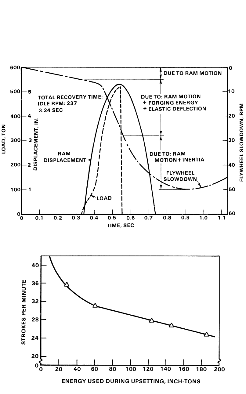
As an example, the variation of load, displace-
ment, and flywheel speed in upset forming of a
copper sample under 1600 ton mechanical press
is illustrated in Fig. 11.13. This press was in-
strumented with strain bars attached to the frame
for measuring load, an inductive transducer
(LVDT) for measuring ram displacement, and a
dc tachometer for measuring flywheel speed. In
Fig. 11.13 it can be seen that, due to frictional
and inertial losses in the press drive, the flywheel
slows down by about (5 rpm) before deforma-
tion begins. The flywheel requires 3.24 s to re-
cover its idling speed; i.e., in forming this part
the press can be operated at a maximum speed
of 18 (60/3.24) strokes/min. For each mechani-
cal press, there is a unique relationship between
strokes per minute, or production rate, and the
available energy per stroke. As shown in Fig.
11.14, the strokes per minute available on the
machine decreases with increasing energy re-
quired per stroke. This relationship can be de-
termined experimentally by upsetting samples,
which require various amounts of deformation
energy, and by measuring load, displacement,
and flywheel recovery time. The energy con-
sumed by each sample is obtained by calculating
the surface area under the load-displacement
curve.
11.2.5 Time-Dependent Characteristics of
Mechanical Presses
The number of strokes per minute, n, was dis-
cussed as part of the energy considerations. As
can be seen in Eq 11.9, the ram velocity is di-
rectly proportional to the number of strokes per
minute, n, and to the press stroke, S. Thus, for
a given press, i.e., a given stroke, the only way
Presses and Hammers for Cold and Hot Forging / 125
Fig. 11.14 Variation of strokes per minute with the energy available for forming in a 500 ton mechanical press. [Altan et al., 1972]
Fig. 11.13
Flywheel slowdown, ram displacement, and forming load in upsetting of copper samples in a 1600-ton mechanical
press. [Altan et al., 1972]
to increase ram velocity during deformation is
to increase the stroking rate, n.
For a given idle-flywheel speed, the contact
time under pressure, t
p
, and the velocity under
pressure, V
p
, depend mainly on the dimensions
of the slide-crank mechanism and on the total
stiffness, C, of the press. The effect of press stiff-
ness on contact time under pressure, t
p
, is illus-
126 / Cold and Hot Forging: Fundamentals and Applications
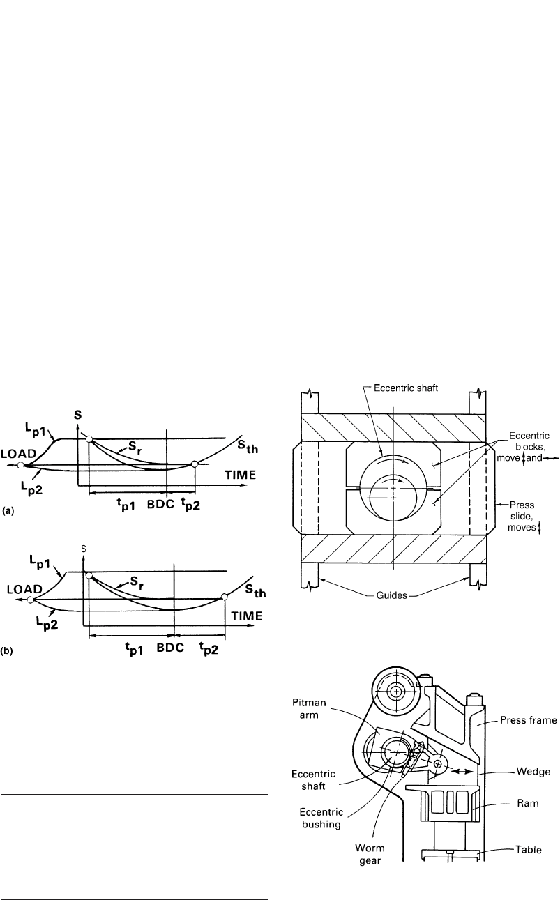
Fig. 11.15
Effect of press stiffness on contact time under
pressure (S
th
⳱ theoretical displacement-time
curve under load). (a) Stiffer press. (b) Less stiff press. [Kienzle,
1959]
Table 11.1 Total deflection under nominal load
on one- and two-point presses of the same
capacity
Relative deflection
One-point
eccentric press
Two-point
eccentric press
Slide Ⳮ pitman arm 30 21
Frame 33 31
Drive shaft Ⳮ bearings 37 33
Total deflection 100 85
[Rau, 1967]
Fig. 11.16
Principle of the scotch-yoke type drive for me-
chanical presses. [Altan et al., 1973]
Fig. 11.17
Principle of the wedge-type mechanical press.
[Rau, 1967]
mized. Assuming the total deflection under load
for a one-point eccentric press to be 100%, the
distributions of total deflection shown in Table
11.1 were obtained from measurements under
nominal load on one- and two-point presses of
the same capacity [Rau, 1967]. It is interesting
to note that a large percentage of the total de-
flection is in the drive mechanism, i.e., slide, pit-
man arm, drive shaft, and bearings.
Drive mechanisms that have considerable
stiffness and off-center loading capability are
provided by (a) the scotch-yoke design (Fig.
11.16) and (b) the wedge-type design (Fig.
11.17). Both these press drives have large bear-
ing surfaces above the slide and can maintain
larger off-center loads than the conventional ec-
centric drive forging presses.
Determination of the Dynamic Stiffness of
a Mechanical Press. Unloaded machine con-
trated in Fig. 11.15. As the load builds up, the
press deflects elastically. A stiffer press (larger
C) requires less time, t
p1
, for pressure buildup
and also less time, t
p2
, for pressure release as
shown in Fig. 11.15(a). Consequently, the total
contact time under pressure (t
p
⳱ t
p1
Ⳮ t
p2
)is
less for a stiffer press.
11.2.6 Accuracy of Mechanical Presses
The working accuracy of an eccentric press is
substantially characterized by two features: the
tilting angle of the ram under off-center loading
and the total deflection under load or stiffness of
the press. Tilting of the ram produces skewed
surfaces and an offset on the part; stiffness in-
fluences the thickness tolerance [Rau, 1967].
Under off-center loading conditions, two- or
four-point presses perform better than single-
point presses because the tilting of the ram and
the reduction forces into the gibways are mini-

Presses and Hammers for Cold and Hot Forging / 127
Table 11.2 Copper samples forged under on-center conditions in the 500 ton mechanical press
Sample size, in.
Sample Height Diameter Predicted load(a), tons Measured load, tons Predicted energy(b), tons Measured energy, tons
1 2.00 1.102 48 45 24 29
2 2.00 1.560 96 106 48 60
3 2.00 2.241 197 210 98 120
4 2.00 2.510 247 253 124 140
5 2.00 2.715 289 290 144 163
6 2.00 2.995 352 350 176 175
(a) Based on an estimate of 50 ksi flowstress for copper at 50% reduction in height. (b) Estimated by assuming that the load-displacement curve has a triangular shape;
that is, energy ⳱ 0.5 load ⳯ displacement. Source: [Douglas et al., 1972]
ditions such as parallelism and flatness of upper
and lower beds, perpendicularity of slide mo-
tion, etc. are important and affect the tolerances
of the forged part. However, much more signifi-
cant are the quantities obtained under load and
under dynamic conditions. The stiffness of a
press C (the ratio of the load to the total elastic
deflection between the upper and lower dies) in-
fluences the energy lost in press deflection, the
velocity versus time curve under load and the
contact time. In mechanical presses, variations
in forging thickness due to volume or tempera-
ture changes in the stock are also smaller in a
stiffer press. Very often the stiffness of a press
(ton/in.) is measured under static loading con-
ditions, but such measurements are misleading.
For practical purposes the stiffness has to be de-
termined under dynamic loading conditions.
To obtain the dynamic stiffness of a mechan-
ical press, copper samples of various diameters,
but of the same height were forged under on-
center conditions. A 500 ton Erie scotch-yoke
type press was used for this study [Douglas et
al., 1972]. The samples of wrought pure electro-
lytic copper were annealed for 1 h at 900 F (480
C). The press setup was not changed throughout
the tests. Lead samples of about 1 in.
2
(645 cm
2
)
and 1.5 in. (38 mm) height were placed near the
forged copper sample, about 5 in. (125 mm) to
the side. As indicated in Table 11.2, with in-
creasing sample diameter the load required for
forging increased as well. The press deflection
is measured by the difference in heights of the
lead samples forged with and without the copper
at the same press setting. The variation of total
press deflection versus forging load, obtained
from these experiments, is illustrated in Fig.
11.18. During the initial nonlinear portion of the
curve, the play in the press driving system is
taken up. The linear portion represents the actual
elastic deflection of the press components. The
slope of the linear curve is the dynamic stiffness,
which was determined as 5800 ton/in. for the
500 ton Erie forging press.
The method described above requires the
measurement of load in forging annealed copper
samples. If instrumentation for load and dis-
placement would be impractical for forgeshop
measurements, the flow stress of the copper can
be used for estimating the load and energy for a
given height reduction.
Ram Tilting in Off-Center Loading. Off-
center loading conditions occur often in me-
chanical press forging when several operations
are performed in the same press. Especially in
automated mechanical presses, the finish blow
(which requires the highest load) occurs on one
side of the press. Consequently, the investigation
of off-center forging is particularly significant in
mechanical press forging.
The off-center loading characteristics of the
500 ton Erie press were evaluated using the fol-
lowing procedure [Douglas et al., 1972]. During
each test, a copper specimen, which requires 220
ton to forge, was placed 5 in. (125 mm) from
the press center in one of the four directions viz.
left, right, front, or back. A lead specimen,
which requires not more than 5 ton, was placed
an equal distance on the opposite side of the cen-
ter. On repeating the test for the remaining three
directions, the comparison of the final height of
the copper and lead forged during the same blow
gave a good indication of the nonparallelity of
the ram and bolster surfaces over a 10 in. (255
mm) span. In conducting this comparison, the
local elastic deflection of the dies in forging cop-
per must be considered. Therefore, the final
thickness of the copper samples was corrected
to counteract this local die deflection.
In off-center loading with 220 ton (or 44% or
the nominal capacity), an average ram-bed non-
parallelity of 0.038 in./ft was measured in both
directions, front-to-back and left-to-right. In
comparison, the nonparallelity under unloaded
conditions was about 0.002 in./ft. Before con-
ducting the experiments described above, the
clearance in the press gibs was set to 0.010 in.
(0.254 mm) [Douglas et al., 1972]. The nonpar-

128 / Cold and Hot Forging: Fundamentals and Applications
Fig. 11.18
Total press deflection versus press loading obtained under dynamic loading conditions for a 500 ton Erie scotch yoke
type press. [Douglas et al., 1972]
allelity in off-center forging would be expected
to increase with increasing gib clearance.
11.2.7 Crank Presses with
Modified Drives
For a long time, eccentric or crank drive sys-
tems were the only type of drive mechanisms
used in mechanical presses. This section dis-
cusses some modified drives such as the
knuckle-joint drive and the linkage drive. The
sinusoidal slide displacement of an eccentric
press is compared with those of a knuckle-joint
and a linkage-driven press (Fig. 11.19). The
relatively high impact speed on die closure and
the reduction of slide speed during the forming
processes are drawbacks that often preclude the
use of eccentric or crank driven press for cold
forging at high stroking rates. However, in
presses with capacities up to a nominal force of
560 tonf (5000 kN), such as universal or blank-
ing presses used for trimming, eccentric or crank
drive is still the most effective drive system.
This is especially true when using automated
systems where the eccentric drive offers a good
compromise between time necessary for pro-
cessing and that required for part transport
[Schuler Handbook, 1998].
Knuckle-Joint Drive Systems. The velocity
versus stroke and the load versus stroke char-
acteristics of crank presses can be modified by
using different press drives. A well-known vari-
ation of the crank press is the knuckle-joint de-
sign (Fig. 11.20). This design is capable of gen-
erating high forces with a relatively small crank
drive. In the knuckle-joint drive, the ram veloc-
ity slows down much more rapidly toward the
BDC than in the regular crank drive. This ma-
chine is successfully used for cold forming and
coining applications.
The knuckle-joint drive system consists of an
eccentric or crank mechanism driving a knuckle

Presses and Hammers for Cold and Hot Forging / 129
Fig. 11.19
Displacement-time diagram: comparison of the slide motion performed by an eccentric, a knuckle-joint, and a link-
driven press. [Schuler Handbook, 1998]
Fig. 11.20
Schematic of a toggle (or knuckle) joint mechan-
ical press
pact unit. The lower joint moves the press frame.
It acts as a slide and moves the attached top die
up and down. Due to the optimum force flow
and the favorable configuration possibilities of-
fered by the force-transmitting elements, a
highly rigid design with very low deflection
characteristics is achieved. The knuckle joint,
with a relatively small connecting rod force,
generates a considerably larger pressing force.
Thus, with the same drive moment, it is possible
to reach around three to four times higher press-
ing forces as compared to eccentric presses. Fur-
thermore, the slide speed in the region 30 to 40
above the bottom dead center is appreciably
lower.
By inserting an additional joint, the kinematic
characteristics and the speed versus stroke of the
slide can be modified. Knuckle-joint and modi-
fied knuckle-joint drive systems can be either
top or bottom mounted. For cold forging, par-
ticularly, the modified top drive system is in
popular use. Figure 11.22 illustrates the princi-
ple of a press configured according to this spec-
ification. The fixed point of the modified
knuckle joint is mounted in the press crown.
While the upper joint pivots around this fixed
point, the lower joint describes a curve-shaped
path. This results in a change of the stroke versus
joint. Figure 11.21 shows this concept used in a
press with bottom drive [Schuler Handbook,
1998]. The fixed joint and bed plate form a com-