Chilingarian G.V. et al. Surface Operations in Petroleum Production, II
Подождите немного. Документ загружается.

245
steam in increasing oil production. If the steam could be forced to contact more of
the reservoir and if the steam channeling could be minimized, the oil recovery
efficiency of steam injection could be markedly improved.
Experimental tests are underway involving the injection of a steam foam solution
and a steam foam encapsulated in a polymer gel to solve the above problems.
Preliminary results with injection of in-situ steam foams indicate that this technique
can alter the steam injection profiles to prevent excessive steam channeling. Prom-
ising preliminary results have also been achieved relative to improvements in both
areal and vertical sweep efficiencies using steam foam injection (Eson and O’Nesky,
1982).
Hotplate steam injection process
Cornell Heavy Oil Process, Inc. is proposing a process which mixes mining
operation and horizontal steam injection in a system designed to recover
75%
of the
crude oil in-place, according to the developer.
A
trial installation is located near
Bakersfield, California
(Oil
and
Gus
Journal,
1982).
The hotplate EOR method uses cyclic steam injection into a heavy-oil-bearing
formation in a hub and spoke pattern from lateral wells. The wells are drilled from a
cavern excavated in an unconsolidated oil sand at a depth of
500
ft. It is assumed
that the thermal efficiency of the project will be greatly improved by exposing all of
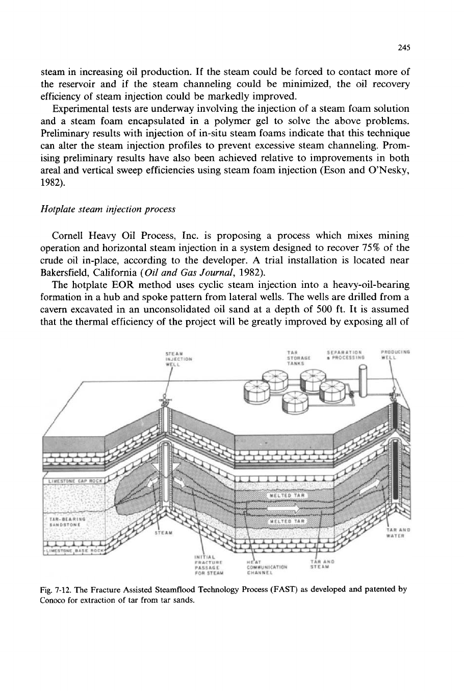
Fig.
7-12.
The Fracture Assisted Steamflood Technology Process (FAST) as developed and patented
by
Conoco
for
extraction
of
tar
from
tar
sands.
246
the formation to the steam front via the lateral wells. The economics
of
this process
as compared to conventional steam injection techniques will not be determined for
several years.
Fracture-assisted steamflood process
The Fracture-Assisted Steamflood Process (FAST Process) has been developed
and patented by Conoco for application on its Street Ranch tar sand extraction
plant located near Uvalde, Texas. As shown in Fig.
7-12
the process consists of
hydraulically fracturing the formation in the horizontal plane at several prede-
termined locations, and then holding the fractures open by the injection of high-
pressure steam. This technique provides heating from both sides of fractures of
selected thicknesses of tar sand formation and greatly expedites the rate of heating
of the formation.
The particular tar for whch the FAST process was developed is one
of
the most
viscous, dense, sulfur-laden hydrocarbons known to exist anywhere in the world
(Britton et al.,
1982).
It has an API gravity of
-2",
a pour point of
180"F,
and an
extrapolated viscosity
of
20
X
lo6
cP at the reservoir temperature
of
95
OF. Testing
is
still underway to determine the economics and recovery efficiency of the FAST
process in ths difficult steam injection application.
tQUIPMENT DESIGNS
FOR
STEAM INJECTION
PROJECTS
Introduction
to
equipment designs
The initiation of steam injection as a commercial enhanced oil recovery technique
created a need for the development of supporting equipment capable of meeting the
unusual requirements of the process. Suitable prototypical designs were quickly
developed as the need materialized in the early
1960's
in the United States, and the
original designs have been continuously improved and expanded in capability in the
subsequent years to meet changing operational requirements and increasingly more
stringent environmental standards.
The single most critical component in a steam injection enhanced oil recovery
project is the steam generator, which must be capable of operating under far more
difficult conditions than those required of the traditional process, i.e., electric utility
boilers.
A
steam generator designed for use on steam injection applications must
meet the following minimum performance requirements:
(I)
Generate steam at pressures ranging from
300
to
2500
psia.
(2)
Use cold feedwater containing up to
8000
ppm of total dissolved solids.
(3)
Operate fully unattended for reasonable periods of time.
(4)
Be relatively portable
so
that it may be readily moved from one location to
(5)
Respond to rapid heat load or steam pressure demands.
another.
241
(6)
Suitable for outdoor installation.
(7)
Easy to service and maintain by oilfield personnel.
(8) Avoid construction that would place it in a boiler classification.
As
a result of the above requirements, the forced circulation, once-through design
of steam generator was developed, and remains the predominant design used on
steam injection projects throughout the world. The original basic design has proven
hghly successful in this demanding application, with over 20 years of successful
performance history.
Other equipment components, whch have to be developed or modified from
existing designs to meet the specific requirements of steam injection projects,
include the following that are described in some detail here:
(1) Steam quality measurement instrumentation.
(2) Low
NO,
burners.
(3)
Feedwater treatment.
(4) Flue gas scrubbers.
(5)
Low-temperature economizers.
(6)
High-temperature thermal packers.
(7)
Casing vent systems.
(8)
Downhole steam generators.
(9)
Solid or waste liquid fuel-fired steam generators.
Steam generator design
In order to successfully generate high-pressure steam from feedwater containing
high total dissolved solids, the concept was evolved of using a once-through, water
tube type of steam generator based on process furnace design principles of relatively
low radiant heat fluxes and uniform radiant section heat distribution. Integral in the
original design concept was the idea of softening the feedwater containing high total
dissolved solids to essentially zero hardness, and leaving sufficient water in the
effluent stream from the steam generator to maintain the concentrated solids in
solution. The basic design concept is utilized in varying degrees in most of the
oilfield steam generators used worldwide on steam injection enhanced oil recovery
projects (see Fig.
7-13).
In general, oilfield steam generators are designed to produce about 80%-quality
steam, thus leaving about 20% of the feedwater as a liquid at the steam generator
outlet to maintain the concentrated solids in solution. The value of 80%-quality
steam was arbitrarily selected as a conservative value at the time the original oilfield
steam generator design was developed in the United States. In feedwater containing
total dissolved solids in the range of 500-2500 ppm, the steam quality can be safely
increased to possibly
90%
without jeopardizing performance. With feedwater con-
taining total dissolved solids over about 8000 ppm, it is recommended that the
steam quality be maintained at a maximum of 80%.
Tests have been conducted in a one million Btu/hr pilot plant steam generator
with feedwater containing 14,000-22,500 ppm total dissolved solids to determine
248
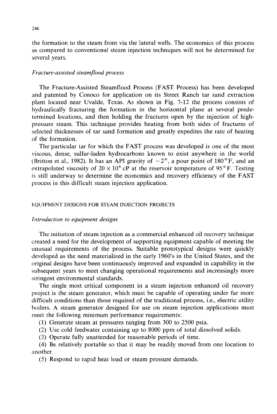
Fig.
7-13.
A
trailer-mounted 25-MMBtu/hr oilfield steam generator
with
ion exchange water softener.
(Courtesy of Struthers Thermo-Flood Corporation.)
both the water softener effectiveness and the ability of this type of steam generator
to accept feedwater having extremely high solids content (Elias et al., 1980). The
tests showed that no solids deposition on the tube walls or tube corrosion were
experienced when generating 73%-quality steam at
2256
psig outlet pressure from
feedwater containing
22,500
ppm total dissolved solids. The effluent liquid in this
instance contained over
83,000
ppm of dissolved solids.
There are certain steam injection installations where the operators have a
preference for injecting 100%-quality steam. The once-through 80%-quality steam
generator can still be used in these instances by installing a steam-water separator
on the outlet of the steam generator. Thermal efficiency can be maintained at an
acceptable value by exchanging heat between the hot liquid separated from the
steam generator discharge and the feedwater. In the majority of steam injection
projects, the 80%-quality steam is injected into the formation, because the hot water
contains an appreciable amount of energy and adds to the displacement volume
of
the injection stream.
In the design and operation of oilfield steam generators, a number of important
factors must be considered and incorporated into the design in order to ensure
satisfactory performance. These factors are discussed in this chapter as a guide to
the reader in evaluating competitive steam generator designs.
249
Tube side
flow
design
In the design of steam generators producing 80%-quality steam from feedwater
containing high total dissolved solids, it is essential to avoid conditions under which
the liquid film on the tube wall can be totally vaporized and deposit the solids it is
carrying in solution on the tube wall. Solids deposition on a localized area of a tube
will impose a high resistance to heat transfer due to the low thermal conductivity of
the solids, and result in a rise in the tube wall temperature. On a typical oilfield
steam generator, a 0.125-in. solids deposit
011
the inside wall of a radiant tube will
increase the tube wall temperature by about
235
OF.
It becomes apparent that any
significant solid deposition can quickly lead to a tube rupture as a result
of
overheating.
The two major factors that can affect liquid dryout and solids deposition on the
inside wall of a radiant tube are
(1)
the heat flux to which the tube is subjected, and
(2) the flow regime in which the steam-water mixture is operating. These two
factors are interrelated and have an equal impact on satisfactory steam generator
performance.
The heat flux in the radiant section, which is discussed in greater detail in
a
subsequent section, is restricted to values ranging from 10-20%
of
those used in
conventional boilers. The reason for the restricted heat flux is the lack
of
any liquid
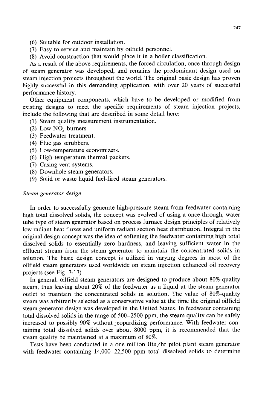
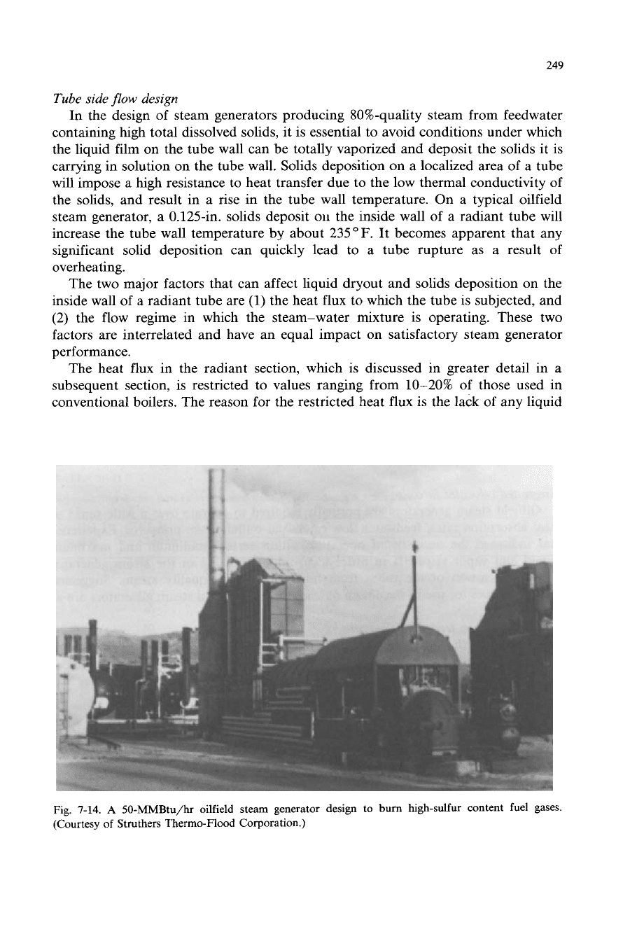
Fig.
7-14.
A
50-MMBtu/hr oilfield steam generator design to
bum
high-sulfur content fuel gases.
(Courtesy of Struthers Thermo-Flood Corporation.)
250
recirculation to increase the liquid volume in the tubes and ensure full wetting of the
tube walls. In an oilfield steam generator operating at 1500 psia, the tube volume
occupied by vapor at the midpoint in the radiant section is over
88%
as compared to
roughly 23% in a conventional boiler. The much higher percentage
of
tube volume
occupied by the vapor in an oilfield steam generator and the high total dissolved
solids content in the liquid dictate the use of much lower rates of heat input to the
radiant tubes than are acceptable in conventional power boilers.
The other major consideration in the tube side design is to ensure that the
steam-water mixture in the radiant section is operating in the proper flow regime,
as
determined by the tube diameter and mass velocity through the tubes, the
percentage
of
vapor at any point, and the relative vapor and liquid densities (Tong,
1965). Fully annular flow with uniform liquid film thickness over the total internal
periphery of the tubes is ideal. Unfortunately, the gravity effect acting on mixed-
phase flow in horizontal tubes results in a reduced liquid film thickness in the upper
quadrant of the tubes. Thus the heat flux in the upper tube quadrant must be less
than that required to totally vaporize the reduced film thickness; otherwise, solids
deposition will inevitably take place. It is interesting to note that, because of the
high vapor velocities employed in oilfield steam generators, the steam heat transfer
film coefficients achieved are adequate to maintain tube wall temperatures at a safe
level. Only when a thin liquid film on the tube wall is totally vaporized by an
excessive rate of heat input, would solids deposition occur on the tube wall with
resultant potential tube failure.
Suggested velocities in coils
Oilfield steam generators are normally required to operate over a wide range of
heat absorption rates, feedwater flow rates, and outlet steam pressures. Experience
has indicated the necessity of operating within certain minimum and maximum
liquid and vapor velocities in order to avoid overheating
of
the steam generator
tubes, or erosion of the tubes from high-velocity 80%-quality steam. Suggested
velocity values for use in the design of once-through oilfield steam generators are as
follows:
It is suggested that the minimum mass velocity through the steam generator tubes
should not be less than
90
lb/ft2-sec. This is equivalent to a minimum linear
velocity of 1.44 ft/sec with cold water. Any lower value throughput has the
potential of depositing solids
on
the tubes, with resulting tube failure.
It
is suggested that the maximum inlet liquid mass velocity through the steam
generator tubes should not exceed 562 lb/ft2-sec, which is equivalent to a linear
velocity of 9 ft/sec. Higher velocities may cause tube and/or U-bend erosion.
The maximum 80%-quality steam velocity leaving the steam generator should not
exceed a reasonable value to minimize the potential for erosion from the high-veloc-
ity
liquid droplets carried by the vapor. The specific volume
of
the 80%-quality
(1)
Minimum feedwater flow rate
(2)
Maximum feedwater flow rate
(3)
Maximum steam
exit
velocity
25
1
steam for determining the velocity may be calculated as follows:
u=xus+(l-x)uw
(7-10)
where:
u
=
specific volume
of
80%-quality steam, ft3/lb;
x
=
fraction of steam;
us
=
specific volume of steam at the operating conditions, ft3/lb; and
u,
=
specific volume of water at the operating conditions, ft3/lb.
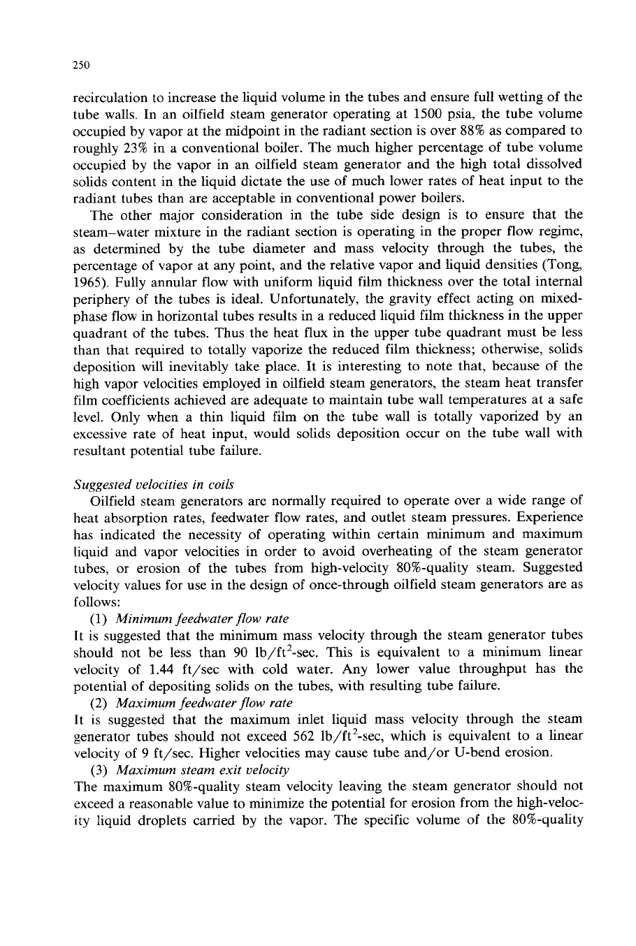
Table 7-VII shows suggested maximum 80%-quality steam flow rates of a
reasonable outlet velocity through various pipe sizes and over a range of pressures.
It should be noted that caution should be exercised in operating an oilfield steam
generator designed for 2500 psia at its full heat input rating, but at a much lower
discharge pressure, because the suggested maximum outlet velocity may be ex-
ceeded. For a 50-million-Btu/hr steam generator designed for
2500
psia operating
pressure and provided with 3-in. schedule 160 IPS tubing, the maximum recom-
mended flow rate at 500 psia operating pressure would be 25,500 lb/hr as compared
to the normal
flow
rate of approximately 52,000 lb/hr at the steam generator design
conditions.
TABLE
7-VII
Suggested maximum flow rates
for
once-through oilfield steam generators
Nominal A.S.A. Flow rate (lb/hr)
pipe size schedule
2
in.
40 15,800
29,300 31,600
32,300
2
in.
80 13,900
25,800
27,800 28,400
2
in.
160 10,500 19,500
21,100 21,500
2;
in.
40 22,500
41,800 45,100
46,100
2f
in.
80 20,000
36,900 39,900
40,800
2f
in.
160 16,700
30,900
33,400 34,100
3
in.
40 34,800
64,500 69,500
71,100
3
in.
80 31,100 57,600
62,100 63,500
3
in.
160 25,500
47,200
50,900 52,100
34
in.
40 46,500
86,200 92,900
95,100
3;
in.
80 43,700
77,500
83,600 85,500
4
in.
40 62,500 110,900
119,700 122,400
4
in.
80 54,100
100,300
108,100 110,500
4
in.
160 43,700
80,900
87,300 89,300
500
psia
1000
psia
1500
psia
2500
psia
Based
on
a reasonable outlet mixture velocity to minimize potential for erosion
of
the
pipe and/or
U-bends.
The values shown are suggested maximum flow rates and are generally not approached in commercial
oilfield steam generators because
of
friction loss considerations.
252
Once-through oilfield steam generators are normally designed for tube side
pressure drops in the range of
100-300
psia. Most of the friction loss through the
steam generator is experienced in the latter half of the radiant coil where the steam
volume is high.
Radiant section design
The proper design of the radiant section of a once-through oilfield steam
generator is the single most important factor in assuring a satisfactory performance.
The radiant section not only absorbs about
65-68%
of the total heat transferred to
the feedwater, but also transfers heat
to
tubes containing a hgh volume
of
steam
and operates under the highest thermal driving force present at any point in the
steam generator. In a satisfactory design, it is essential to use relatively low heat
fluxes, and take special precautions to insure the maximum uniformity of heat
distribution. The importance of these factors is discussed in the following para-
graphs (see Fig.
7-15).
The radiant heat flux is measured in Btu/ft2-hr, and is determined by dividing
the total heat absorbed in the radiant section by the radiant heat transfer surface.
The calculation method used
in
establishing the percentage of heat released by the
combustion
of
the fuel, which is absorbed in the radiant section, is treated in detail
RADIATING
PLANE
REFRACTOR
..........................
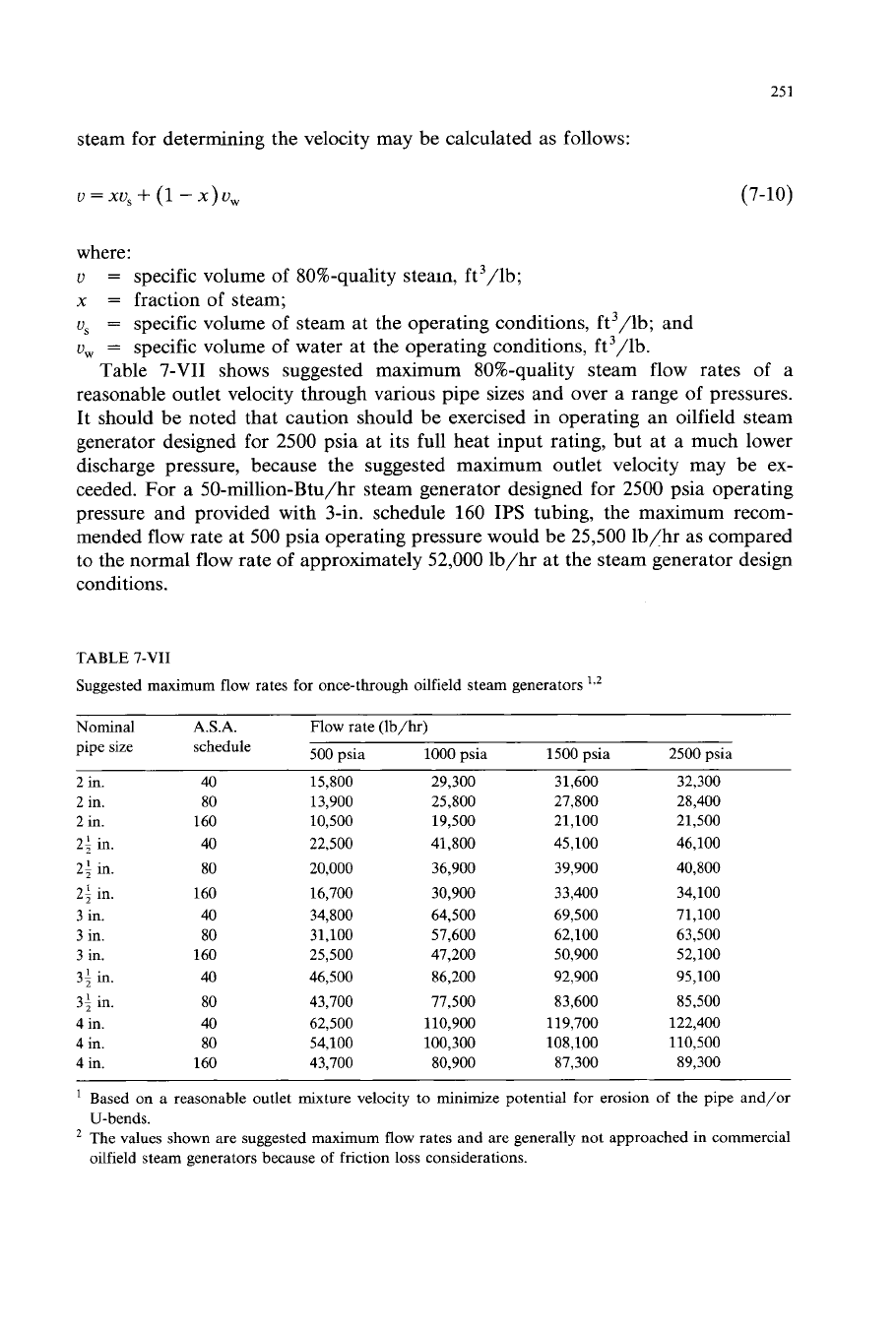
Fig.
7-15.
Heat
flux
around the circumference
of
a tube in a single row subjected to radiant heat from
one side. (After Sutherland,
1961;
courtesy of the American Institute
of
Chemical Engineers.)
253
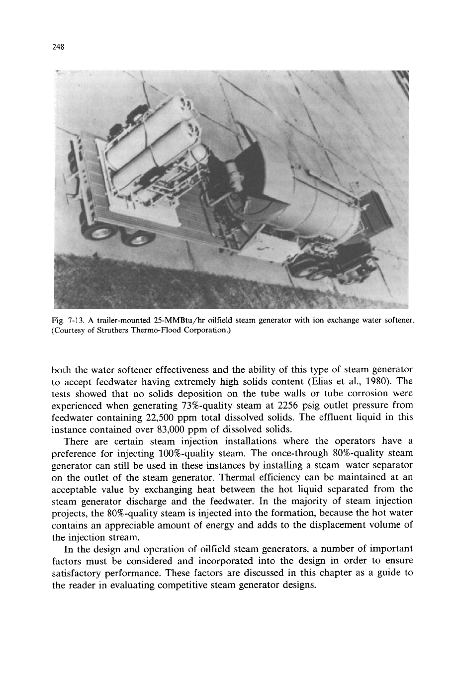
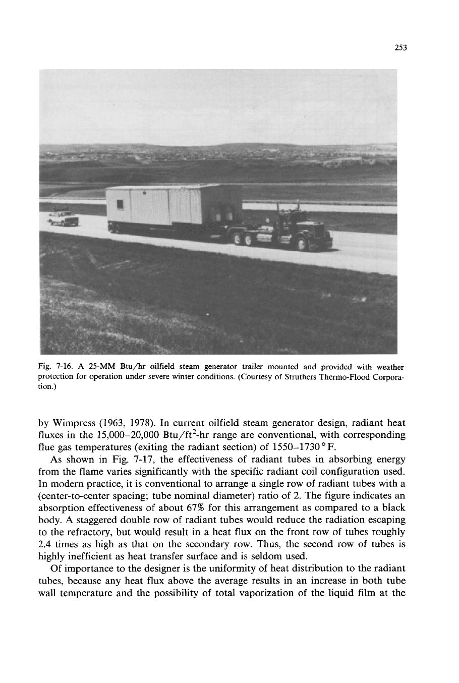
Fig.
7-16.
A
25-MM
Btu/hr oilfield steam generator trailer mounted and provided with weather
protection for operation under severe winter conditions. (Courtesy of Struthers Thermo-Flood Corpora-
tion.)
by Wimpress (1963, 1978). In current oilfield steam generator design, radiant heat
fluxes in the
15,000-20,000
Btu/ft2-hr range are conventional, with corresponding
flue gas temperatures (exiting the radiant section) of 1550-1730
F.
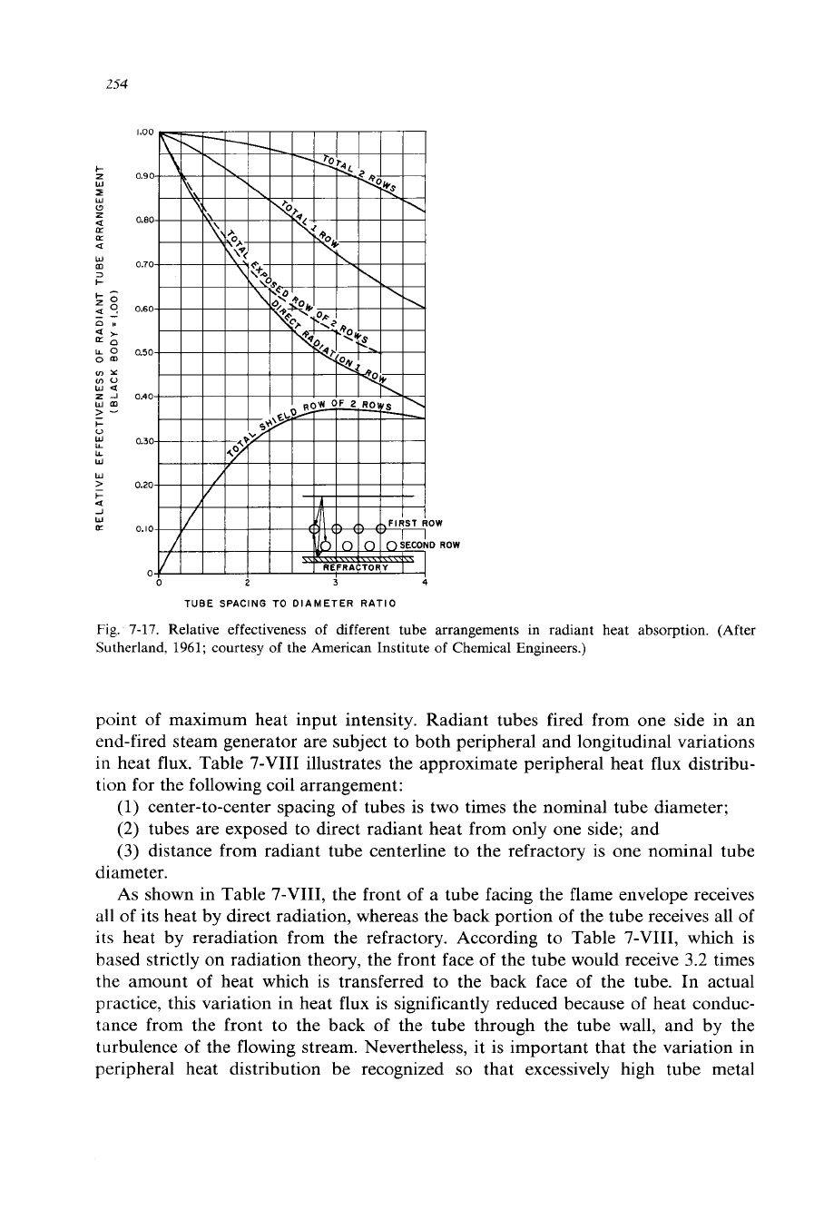
As
shown in Fig.
7-17,
the effectiveness
of
radiant tubes in absorbing energy
from the flame varies significantly with the specific radiant coil configuration used.
In modern practice, it is conventional to arrange a single row of radiant tubes with a
(center-to-center spacing; tube nominal diameter) ratio
of
2.
The figure indicates an
absorption effectiveness of about 67% for this arrangement as compared to a black
body.
A
staggered double row
of
radiant tubes would reduce the radiation escaping
to the refractory, but would result in a heat
flux
on the front row of tubes roughly
2.4
times as high
as
that on the secondary row. Thus, the second row of tubes is
highly inefficient as heat transfer surface and is seldom used.
Of
importance to the designer is the uniformity of heat distribution to the radiant
tubes, because any heat flux above the average results in an increase in both tube
wall temperature and the possibility
of
total vaporization of the liquid film at the
254
W
3
+
m
+
u
W
U
W
a
2
W
LT
ow
0
ROW
0
2
3
4
TUBE
SPACING TO DIAMETER RATIO
Fig.
7-17.
Relative effectiveness
of
different tube arrangements in radiant heat absorption. (After
Sutherland,
1961;
courtesy of the American Institute of Chemical Engineers.)
point of maximum heat input intensity. Radiant tubes fired from one side in an
end-fired steam generator are subject to both peripheral and longitudinal variations
in
heat flux. Table
7-VIII
illustrates the approximate peripheral heat flux distribu-
tion for the following coil arrangement:
(1)
center-to-center spacing of tubes is two times the nominal tube diameter;
(2) tubes are exposed to direct radiant heat from only one side; and
(3) distance from radiant tube centerline to the refractory is one nominal tube
diameter.
As shown in Table
7-VIII,
the front
of
a tube facing the flame envelope receives
all
of its heat by direct radiation, whereas the back portion of the tube receives all of
its
heat by reradiation from the refractory. According to Table
7-VIII,
which is
based strictly on radiation theory, the front face of the tube
would
receive 3.2 times
the amount of heat which
is
transferred to the back face of the tube.
In
actual
practice, this variation in heat flux is significantly reduced because of heat conduc-
tance from the front to the back of the tube through the tube wall, and by the
turbulence of the flowing stream. Nevertheless, it is important that the variation in
peripheral heat distribution be recognized
so
that excessively high tube metal