Canale L.C.F., Mesquita R.A., Totten G.E. Failure Analysis of Heat Treated Steel Components
Подождите немного. Документ загружается.

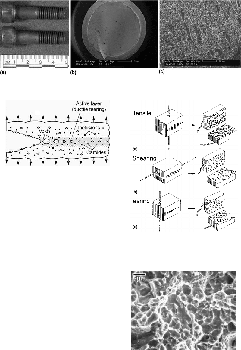
void formation (Ref 10). If the interface between
the particles and the matrix is weak, then voids
form and grow readily. Substantial plastic
deformation occurs. Fracture occurs when the
voids reach a critical size. These voids sub-
stantially reduce the cross section, with the
resulting local plastic instability (Ref 11). These
voids coalesce to form a central crack perpen-
dicular to the applied tensile stress. Depending
on the applied stresses, the shape and config-
uration of the dimple shape can be changed
(Fig. 10). This fact is important in dete rmining
the type of loading during a postfract ure inves-
tigation. Dimples are small and can only be
detected by using electron microscopy (Fig. 11).
The presence of inclusions in steel plays a
major role in the ductility of steel. As indicated
previously, the inclusions fracture and separate
from the matrix during decohesion. Therefore,
the deformability of these inclusions is impor-
tant to determine the ductility of steel.
Nearly all steels have nonmetallic inclusions.
The size and frequency of these inclusions is
determined by the methods described in ASTM
E45 (Ref 12). The cleanliness of the steel is
Fig. 8
Fracture of an ISO 12.9 bolt by ductile torsional overload. (a) Overall view of fracture. (b) Smooth and fibrous fracture as seen
through the SEM. (c) Microvoid coalescence (dimples)
Fig. 9
Schematic showing the formation of microvoid coal-
escence
Fig. 10
Schematic representation of the creation of dimples
in a loaded member by (a) simple tension, (b) shear
loading, and (c) tearing
Fig. 11 Microvoid coalescence as seen through the SEM
52 / Failure Analysis of Heat Treated Steel Components
Name ///sr-nova/Dclabs_wip/Failure_Analysis/5113_43-86.pdf/Chap_02/ 18/8/2008 2:54PM Plate # 0 pg 52
important to the ductility of the steel. All other
things being equal, the steel with the lower
inclusion size, shape, and frequency will have a
greater ductility than another steel with a greater
inclusion count. Modern steelmaking practices
generally produce low inclusion content. Often,
steels for aerospace applications require a fre-
quency/severity determination of inclusions in
accordance with AMS 2300, AMS 2301, AMS
2303, or AMS 2304 (Ref 13–16). A specific-
sized test specimen must be heat treated and
examined using magnetic particle inspection.
The procedures are outlined in the aforemen-
tioned specifications.
The inclusions found in steels have been
divided into five categories related to their
deformation behavior (Ref 17):
The inclusions Al
2
O
3
and calcium alumi-
nates are produced during deoxidation of
steel during the production of molten steel.
They are brittle at practically all tempera-
tures.
Spinel-type oxides are not deformable up to
1200
C but may be deformed above this
temperature.
Silicates of calcium, manganese, iron, and
aluminum in various proportions are brittle
inclusions at room temperature but become
more deformable at higher temperatures.
The formability increases as the melting
temperature of the silicate decreases. There-
fore, aluminum silicate has much less form-
ability than the lower-melting manganese
silicates.
FeO and (FeMn)O are deformable at room
temperature but gradually become more
brittle at temperatures above 400
C.
Manganese sulfide (MnS) is the most com-
mon inclusion found in steel, and it is
increasingly deform able as the temperature
falls. The morphology of the MnS inclusions
changes, depending on how they were
formed.
Ductile failure can occur with any of the
types of inclusions. This is true whether it is
the brittle alumina-type inclusions or the more
ductile sulfide-type inclusions. Inclusions gen-
erally initiate ductile crackin g above a critical
size. Coarser inclusion sizes tend to have a larger
local stress-concentration factor, which can
cause local decohesion and microcrack forma-
tion. Work by Maropoulos and Ridley (Ref 18)
has shown the effect of volume fraction of iron-
alumina on the ductility of steel. Increasing
amounts of inclusions reduce the ductility of the
steel. A reduction in the yield stress, due to the
stress concentrations around the inclusions, is
evident at low volume concentrations of inclu-
sions.
The presence of inclusions in the size range of
1to30m m reduces the energy absorbed during
ductile fracture. Fine dispersions of ductile
inclusions will delay the onset of cleavage-type
fracture by localized relaxation of stresses. At
the same time, the yield stress also increases.
During deformation, forming, or forging, the
ductile inclusion MnS has a marked effect on the
ductility of the final product. Types 1 and 2 MnS
inclusions will elongate on deformation, while
type 3 MnS inclusions will rotate into the rolling
plane. This will reduce toughness and ductility
in the transverse direction. Type 2 inclusions are
the most harmful to ductility and toughness, so
some effort is being made to eliminate these
inclusions by ladle addi tions of other strong
sulfide formers, such as titanium, zirconium, and
calcium.
Ductility is also influenced by the fact that
MnS contracts more than the iron matrix upon
cooling. The bond between the MnS inclusion
and the matrix is not strong enough to preve nt
microvoid formation. Because MnS inclusions
tend to form as strings or stringers along the
rolling direction, the toughness and ductility
are strongly influenced in the rolling direction.
Transverse to the rolling direction, ductility and
toughness are much worse.
In a similar fashion to that of inclusions, the
distribution of carbides can also influence the
toughness and ductility of the steel. The strain
needed for void formation decreases with
increasing carbide volume fraction. Spheroidal
carbides will not crack at small strains and
exhibit decohesion. Spheroidized steel is much
more ductile than similar steel of the same
hardness cont aining only ferrite and pearlite.
Pearlite has a lower critical strain for void for-
mation. In addition, when a crack or void forms
in a pearlitic matrix, it will tend to run along
the length of a pearlite lamella. Examining this
type of fracture under the SEM reveals that the
base of the dimples contain fractured pearlite
lamella.
Brittle Fracture
Very little plastic deform ation and a shiny
fracture surface characterize brittle fractures.
Often, chevron patterns point back to the origin
Overview of the Mechanisms of Failure in Heat Treated Steel Components / 53
Name ///sr-nova/Dclabs_wip/Failure_Analysis/5113_43-86.pdf/Chap_02/ 18/8/2008 2:54PM Plate # 0 pg 53
of failure (Fig. 12) (Ref 19). It can occur at low
stress and propagate with rapidity, often at
speeds approaching the speed of sound in the
failed material.
Since the early 1940s, there has been tre-
mendous growth in the number of large welded
structures. Many of these structures have failed
catastrophically in service, most notably the
“Liberty ships” (Ref 20) used to transport war
material during World War II. Analysis of the
fracture surfaces of the failures (Ref 21) indi-
cated that they initiated at a notch and propa-
gated with no plastic deformation. These
notches were of three types:
Design features: Structural members were
rigidly joined at angles less than 90
and
then welded.
Fabrication details: Procedures used during
the manufacture of the part caused the
formation of notches. Welding arc strikes,
gouges, and fitting procedures created
physical notches. Welding procedures and
heat treatment caused metallurgical or
microstructural notches to occur from abrupt
changes in microstructure or the production
of microstructures that were brittle. Features
such as porosity from welding or casting also
caused brittle fracture initiation.
Material flaws: These flaws resulted from
melt practice at the mill and appeared as
large inclusions, internal oxidation, porosity,
or segregation.
In brittle fractures, limited energy is absorbed
by the fracture. Energy is absorbed through
regions of small plastic deformation. Individual
grains separate by cleavage along specific
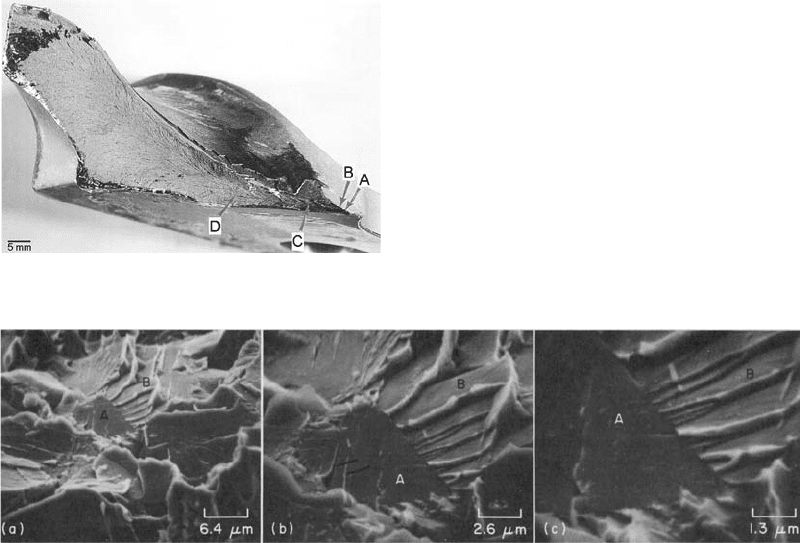
crystallographic planes. This is shown in Fig. 13.
Visually, little or no plastic deformation or
distortion of the shape of the part characterizes
brittle fractures. The fracture is usually flat and
perpendicular to the stress axis. The fracture
surface is shiny, with a grainy appearance.
Failure occurs rapidly, often with a loud report.
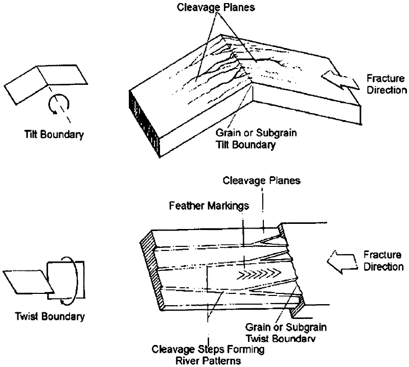
Because the brittle cleavage is crystallographic
in nature, the fracture appearance is faceted.
Often, other features are present, such as river
patterns (Ref 23). These are shown schemati-
cally in Fig. 14.
There are three basic factors that contribute to
a cleavage type of fracture in steels. They are:
Triaxial stress state that forms at a notch,
similar to that described previously
Low temperature
High strain rate or rapid loading rate
These three factors do not have to be present
for cleavage-type fractu re to occur. Most brittle,
cleavage-type fractures occur when there is a
triaxial stress state and low temperature. This is
Fig. 12
Chevron markings point back to the origin of failure
in brittle steels. Source: Ref 19
Fig. 13
Cleavage fracture in a low-carbon steel, seen through an SEM. Cleavage fracture in a notched impact specimen of hot-rolled
1040 steel broken at 196
C(320
F), shown at three magnifications. The specimen was tilted at an angle of 40
to the
electron beam. The cleavage planes followed by the crack show various alignments, as influenced by the orientations of the individual
grains. Grain A, at center in fractograph (a), shows two sets of tongues (see arrowheads in fractograph b) as a result of local cleavage along
the {112} planes of microtwins created by plastic deformation at the tip of the main crack on {100} planes. Grain B and many other facets
show the cleavage steps of river patterns. The junctions of the steps point in the direction of crack propagation from grain A through grain
B, at approximately 22
to the horizontal plane. The details of these forks are clear in fractograph (c). Source: Ref 22
54 / Failure Analysis of Heat Treated Steel Components
Name ///sr-nova/Dclabs_wip/Failure_Analysis/5113_43-86.pdf/Chap_02/ 18/8/2008 2:54PM Plate # 0 pg 54
actuated by a high rate of loading. Many types of
tests have been developed to determine the
susceptibility of steels to brittle behavior. These
tests include the Charpy impact test (ASTM
E23) (Ref 24) and the fracture toughness test
(ASTM E399) (Ref 25). Others include the nil-
ductility test (ASTM E208) (Ref 26) and
dynamic tear test (ASTM E604) (Ref 27).
The notch toughness of low- and medium-
strength steels is highly dependent on tempera-
ture. There is a transition from ductile fracture to
brittle fracture as the temperature decreases.
One criterion for the transition temperature is the
nil-ductility temperature (NDT). The NDT is the
temperature where fracture becomes 100%
cleavage, and there is essentially no plastic
deformation.
Changes in the NDT can be produced by
changes in microstructure and chemistry. The
largest change can be effect ed by changes in the
amount of carbon and manganese. The NDT is
lowered by approximately 6
C (10
F) for
every 0.1% increase in the manganese con-
centration. Increasing the carbon content also
lowers the NDT. The manganese-carbon ratio
should be approximately 3 to 1 for good notch
toughness.
Decreasing the concentration of phosphorus
also decreases the NDT. Nitrogen causes the
NDT to increase (more brittle). However,
because of the interaction with other alloying
elements in steel, it is difficult to quantify the
increase of NDT with increasing nitrogen con-
centration.
Fig. 14 Schematic of river patterns formed in brittle materials. (a) Tilt boundary. (b) Twist boundary. Sourc e: Ref 23
Overview of the Mechanisms of Failure in Heat Treated Steel Components / 55
Name ///sr-nova/Dclabs_wip/Failure_Analysis/5113_43-86.pdf/Chap_02/ 18/8/2008 2:54PM Plate # 0 pg 55
Nickel is beneficial for increasing ductility.
Up to 2% Ni is effective in lowering the NDT.
Increasing concentrations of silicon have the
effect of increasing the NDT. Chromium has
nearly no effect, while molybdenum is extre-
mely effective in increasing the ductility of
steels and drastically decreasing the NDT.
Oxygen strongly decreases the ductility. It can
also cause an increased propensity for inter-
granular fracture by creating brittle oxides at the
grain boundaries. Decreasing the grain size has a
strong effect on increasing the ductility and
notch toughness.
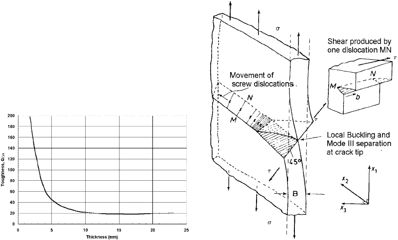
Section thickness can also influence ductile
and brittle behavior (Ref 28). The results showed
that there was considerable variation of tough-
ness with the thickness of the specimen (Ref 29,
30). Further, at large thickness, the toughness
appeared to reach a constant value (Fig. 15)
(Ref 31). Within this curve, there are three
apparent regions. First, there is the region where
maximum toughness is obtained (thin sections).
Second, there is the region of intermediate
toughness, and lastly, a region with relatively
constant toughness (thick sections).
In the first region, the fracture appears to
consist entirely of a shear lip, or, in other words,
the fracture surface is inclined at an angle
of approximately 45
to the tensile axis. In this
situation, the stress in the direction of the
thickness of the specimen tends toward zero,
and a state of plane stress is achieved. As the
specimen is pulled, it experiences buckling. Be-
cause of this buckling, yielding occurs on the
through-thickness planes at an angle of 45
to
the tensile axis. Crack extension occurs by
sliding. This sliding motion is achieved by the
movement of a number of screw dislocations
(Ref 32, 33) on the 45
plane, as shown in
Fig. 16.
In the intermediate range, the fracture beha-
vior is complicated. The fracture does not con-
sist of entirely slant-type fracture, nor does it
contain entirely a flat plane-strain-type fracture.
Instead, the regions of flat and slant fracture are
approximately equal. At the thin end of the
thickness range, the slant ligaments on either
side of the testpiece carry most of the load. At
the thick end of the range, the side ligaments
carry a much smaller percentage of the load. The
amount of flat fracture increases. This is shown
schematically in Fig. 17. It has been found (Ref
28) that the amount of flat fracture depends only
on the thickness of the test specimen and was
independent of crack length.
In the third region, the fracture consists of
predominantly flat fracture. Some evidence of
very small shear lips may be present at the later
part of fracture. Fracture is catastrophic and
rapid. No plastic deformation is evident. In this
third region, any increase in the thickness of the
testpiece causes no further decrease in the
toughness.
These fracture patterns are useful in deter-
mining the state of stress within a failed com-
ponent and can help to understand the
mechanism of failure.
One famous failure involving brittle fracture
was the “Great Boston Molasses Disaster”
Fig. 15 Variation of toughness with thickness Fig. 16 Mode of separation in a thin sheet
56 / Failure Analysis of Heat Treated Steel Components
Name ///sr-nova/Dclabs_wip/Failure_Analysis/5113_43-86.pdf/Chap_02/ 18/8/2008 2:55PM Plate # 0 pg 56
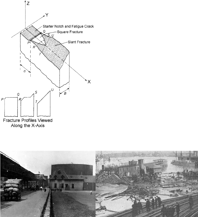
(Ref 34). In this failure, the United States
Alcohol Company fabricated a large cast iron
molasses tank in Boston in December 1915. This
tank was 27 m (90 ft) wide and 17.7 m (58 ft)
tall, with a head of 15 m (49.5 ft) of molasses. It
was fabricated of cast iron plates riveted toge-
ther. It held 8.7 · 10
6
L (2.3 million gal) of
molasses, ostensibly used for the fermentation of
ethanol used for liquor. The man who oversaw
construction could not read blueprints, nor did
he have any technical training. No engineers or
architects were consulted to ensure that the tank
was constructed safely. On January 15, 1919, the
tank exploded with great force, and the streets of
Boston were flooded with waves of molasses
from 2 to over 4 m (8 to 15 ft) tall (Fig. 18). This
great wall of molass es was reported to have
moved at speeds up to 35 miles (56 km) per
hour and devastated a large section of Boston
along Commercial Street between Copps Hill
and the playgroun d of North End Park. Half-inch
steel plates were torn apart, and these plates
were thrown with enough force to cut girders of
the elevated railway. This explosion, and the
subsequent wave of molasses, resulted in 21
people killed, 150 people injured, many build-
ings destroyed, and an entire area devastated.
The elevated train trestles were knocked over.
Early accounts of the disaster included reports
that the tank was destroyed by anarchists. In a
trial, it was found that the company was liable
for $628,000 in damages (in 2007 dollars,
approximately $7,000,000). Investigation many
years later indicated that the probable cause was
brittle fracture of the tank at the rivets, with the
temperature below the ductile-to-brittle transi-
tion temperature. One interesting result of this
disaster was that Massachusetts and many other
states created laws to certify engineers and to
regulate construction. It also required stamped
drawings certifying that an engineer had
reviewed the plans. It was this failure that was
the origin of the professional engineer’s license
and stamp, as it is known today (2007). As a side
note, the 18th Amendment was ratified and
Prohibition signed into law on January 16, 1919.
In another example of brittle fracture, an AISI
4330V hook-point, used for the arrestment of
Fig. 17 Schematic of fracture in the intermediate range
Fig. 18
The Great Boston Molasses Disaster. Twenty-one people were killed and over 150 buildings destroyed as the result of
2.3 million gal of molasses flooding North Boston.
Overview of the Mechanisms of Failure in Heat Treated Steel Components / 57
Name ///sr-nova/Dclabs_wip/Failure_Analysis/5113_43-86.pdf/Chap_02/ 18/8/2008 2:55PM Plate # 0 pg 57
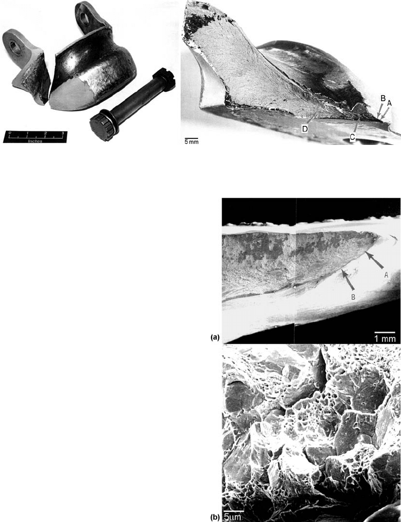
naval aircraft on landing, failed during field
trials during the 13th arrestment. The landing
configuration was severe, with high aircraft sink
rates, high aircraft gross weight, and landing at a
large angle to the cable. The hook-point failed at
the inner fillet radius of the right-hand lug
(Fig. 19). The hook-point successfully engaged
the arrestment cable, with no other aircraft
damage. The part was forged, machined, heat
treated, and hard surfaced in the cable groove,
using a high-velocity oxyfuel coating for wear
resistance. Examination showed that the micro-
structure of the hook-point was quenched and
tempered martensite. Hardness measurements
showed that the hook-point had a substantially
higher hardness (HRC 54) than the specified
hardness of HRC 46 to 48. The chemistry of the
hook-point indicated that it was at the high side
of the specification, increasing the hardenability
of the steel and increasing the resistance to
tempering. Hydrogen measurements indicated
that the hydrogen content was 0.2 ppm. The
high strain rate during landing and the low
concentration of hydrogen precluded failure by
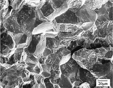
hydrogen embrittlement. An SEM examination
of the fractu re surface showed that the fracture
contained micro void coalescence and quasi-
cleavage, suggestive of brittle failure (Fig. 20).
Charpy impact testing showed that the impact
toughness of the as-received part was sig-
nificantly lower than a part of the same chem-
istry properly tempered to HRC 46. Finite
element analysis showed a high localized stress
concentration at the lug inside fillet radius.
It also showed that the stresses were highly
triaxial. Ba sed on the analysis, it was determined
that the hook-point lug failed by quasi-cleavage,
and that the failure was aggravated by high local
stress conce ntration at the fillet radius, improper
heat treatment (making the materia l more
Fig. 19
Arresting gear hook-point, manufactured from AISI 4330V, that failed during landing. Failure occurred at the inner fillet
radius of the right-hand lug
Fig. 20
SEM fractographs showing (a) location of origin at the
inner fillet radius and (b) quasi-cleavage evident on
the fracture surface
58 / Failure Analysis of Heat Treated Steel Components
Name ///sr-nova/Dclabs_wip/Failure_Analysis/5113_43-86.pdf/Chap_02/ 18/8/2008 2:55PM Plate # 0 pg 58
brittle), and extremely high dynamic loading. It
was recommended that the radius be made larger
to reduce the stress concentration and also to
retemper the hook-p oints to meet specification.
Intergranular Brittle Fracture
Another form of brittle fracture is called
intergranular cracking. In this fracture mechan-
ism, failure occurs by decohesion along grain
boundaries and not on specific crystallographic
planes, such as in cleavage fracture. Inter-
granular cracking can have several different
causes. Typical causes of intergranular cracking
in steel alloys include:
Quench-age embrittlement: Cooling of car-
bon steels and low-alloy steels from sub-
critical temperatures can precipitate carbides
within the microstructure. The strength is
raised, but toughness is lost.
Quench cracking: During quenching, the
transformational and residual stresses
developed during quenching of steels can
cause cracking during heat treatment.
Tempered martensite embrittlement: Within
the range where blue-purple oxides can form
on steels (230 to 370
C, or 450 to 700
F),
precipitates can form that increase the tensile
strength and hardness while reducing the
ductility and toughness.
Temper embrittlement: Quenched steels
containing appreciable amounts of manga-
nese, silicon, nickel, or chromium are sus-
ceptible to temper embri ttlement if they
contain even trace amounts of antimony, tin,
or arsenic. Embrittlement of susceptible
steels can occur after heating in the range of
370 to 575
C (700 to 1070
F) but occurs
most rapidly at approximately 450 to 475
C
(840 to 885
F).
Graphitization: This happens when the
pearlite in steels begins to decompose into
ferrite and graphite following very long,
high-temperature service, for example, in
steam power stations. For these applications,
a few steels turn out to be satisfactory, while
many others are subject to graphitization.
Internal oxidation: This is one of the com-
mon failures in high-temperature, oxidizing
conditions.
Liquid metal embrittlement or solid metal
embrittlement: Intermetallic compounds
form at grain boundaries when low-melting-
temperature metals (cadmium, zinc, etc.)
penetrate by diffusion. An example would be
galvanized steel where the zinc has diffused
into the steel in the vicinity of 420
C
(787
F).
Hydrogen embrittlement: The presence of
hydrogen and static loads or a low strain rate
can result in hydrogen embrittlement.
Stress-corrosion cracking
Grain-boundary decohesion at elevated
temperatures (creep rupture)
The fracture surface appearance of inter-
granular cracking is generally shiny and faceted.
It has a “rock-candy” appearance. Often, when
the mechanism is from corrosion, the corrosion
product is present. This can dull the appea rance
of the facets. The appearance of intergranular
fracture is most clearly seen in the electron
microscope, and an example is shown in Fig. 21.
Quench cracking is the limiting case of
excessive residual stresses exceeding the tensile
strength of the material. Two processes con-
tribute to quench cracking, as well as distortion
and residual stresses. The first process is the
stress from the volume expansion of martensite
during transformation from austenite to mar-
tensite. The second source is from thermal stress
due to differential contraction due to different
cooling rates in the steel. The transformational
stress from the formation of martensite is pri-
marily responsible for cracking during quench-
ing, and thermal stresses from differential
cooling are usually from subcritical heat treat-
ments such as annealing.
During quenching, the volume expands from
the close-packed face-centered cubic structure
of austenite to the body-centered tetragonal
structure of martensite. This volume expansion
Fig. 21
Intergranular fracture from hydrogen embrittlement,
as seen through the SEM
Overview of the Mechanisms of Failure in Heat Treated Steel Components / 59
Name ///sr-nova/Dclabs_wip/Failure_Analysis/5113_43-86.pdf/Chap_02/ 18/8/2008 2:55PM Plate # 0 pg 59
is approximately 4% and is related to the carbon
content of the steel. During quenching, the outer
surface of the part cools first and transforms to
martensite. There is an attendant volume
expansion at the surface, and the untransformed
and still hot interior surface usually has suffi-
cient plasticity to accommodate the changes in
the part volume. The outside surface is in com-
pression. Upon cooling, the interior of the part
also transforms to martensite but is constrained
by the hard outside surface layer of previously
transformed martensite. On the transformation
of the inner core, a volume expansion occurs in
the interior of the part, and the outer surface is
placed in tension. If quenching is severe, the
resulting tensile residua l stresses can exceed the
ultimate tensile stress of the surface untempered
martensite. Cracking is interg ranular and often
exhibits an oxide scale on the fracture surface. If
cracking occurred during quenching, remnants
of quench oil can be found on the surface of the
crack, and often, elevated-temperature scale is
apparent. Cracking can be delayed due to the
transformation of retained austenite. This is one
reason why it is recommended to temper parts
immediately after quenching. Should delayed
quench cracking occur, then the temper scale
is thinner and often shows the characteristic
temper colors, indicative of the temper tem-
perature. High-carbon steels and steels with high
hardenability are the mos t prone to quench
cracking.
Surface features such as sharp radii, large
changes in section, or the presence of laps, burrs,
rough-machined surfaces, and other surface
discontinuities increase the constraint during
quenching and increase the propensity toward
quench cracking.
Quench cracking can be mitigated by
improved surface condition and the removal
of scale, burrs, and sharp edges. Geometry
changes, by increasing transitions from thin
to thick sections, and generous radii can also
help reduce quench cracking. The use of higher-
hardenability alloys will also reduce the pro-
pensity for crackin g, because it will allow a
reduced quench rate to achieve the sam e prop-
erties. Reducing the austenitizing temperature
or reducing the temperature differential between
the austenitizing temperature and the quenchant
temperature will reduce the propensity for crack-
ing. Often, the geometry is set, as is the alloy of
the part. In this case, the heat treater can reduce
the quench rate or use martempering to reduce
quench cracking.
Martempering is the process of using high-
temperature quench oils and quench oil tem-
peratures of 90 to approximately 200
C (200 to
400
F). The part is quenched into the high-
temperature oil, and the parts are allowed to
equilibrate or at least minimize the temperature
gradient across the interior of the part. The part
is then removed from the oil and allowed to cool
in any convenient manner. This method has
proven to be very effective in reducing quench
cracking as well as distortion from quenching.
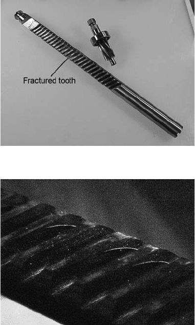
A long pinion gear failed in service near the
midlength of the shaft (Fig . 22). One gear tooth
fractured during service, resulting in the gear
being removed from service and sent to the
laboratory for failure analysis. Magnetic particle
inspection, using a fluorescent dye, revealed
the presence of multiple linear indications on
cracking of the gear tooth faces (Fig. 23).
Examination of the fracture surface showed a
discolored region at the origin of cracking
(Fig. 24). This discolored region was attributed
Fig. 22 As-received pinion gear that failed in service
Fig. 23
Magnetic particle inspection of the failed pinion gear
showed arc-shaped cracks on the gear tooth faces.
60 / Failure Analysis of Heat Treated Steel Components
Name ///sr-nova/Dclabs_wip/Failure_Analysis/5113_43-86.pdf/Chap_02/ 18/8/2008 2:55PM Plate # 0 pg 60

to oxidation that occurred during heat treat-
ment. The coloration of the oxide scale sug-
gested that the oxidation o ccurred during
tempering (Fig. 25, 26). If the crack was pre-
existing prior to heat treatment, it would be
darker and thicker.
Examination of the tooth faces showed sec-
ondary cracking at regions of tearing and
smearing along the tooth face (Fig. 27), sug-
gestive of abusive machining practice, including
the use of a tool that was dull or excessive feeds
and cutting speeds.
Region of Cracking
Fig. 24 Overall view of the cracked pinion showing the location of the fracture and the presence of a discolored region
Fracture
Origins
Region of Discoloration
Fig. 25
Closeup of the fracture region showing the dis-
colored region. The color of the oxidation indicated
that the crack occurred after quenching and during the tempering
operation.
Region of Discoloration
Smeared surface showing
secondary cracking
Fig. 26
Rough machining at the surface of the tooth showing
smearing and tearing of the machined surface. This is
suggestive of abusive machin ing, due to dull cutting tools,
inadequate coolant, or excessive speeds and feeds.
Overview of the Mechanisms of Failure in Heat Treated Steel Components / 61
Name ///sr-nova/Dclabs_wip/Failure_Analysis/5113_43-86.pdf/Chap_02/ 18/8/2008 2:55PM Plate # 0 pg 61