Canale L.C.F., Mesquita R.A., Totten G.E. Failure Analysis of Heat Treated Steel Components
Подождите немного. Документ загружается.

a thin thickness that the liquid metal, even at the
appropriate temperature, cannot fill them com-
pletely.
The component that shows this kind of defect,
depending on the size and location of the joint,
must be discarded, since recovery with a weld is
not recommended from a metallurgical point of
view or, depending on the cost-benefit ratio,
is not justified. This defect is usually seen, but
can occur and be unnoticed initially, in compo-
nents with complex geometry and abrupt vari-
ation of mass, where it is used to obtain a large
number of cores that could provide details dif-
ficult to be observed by quality control. In these
cases, the defect will only be located when there
are cracks/disruption in heat treatment or leak-
age and fracture when the component is in
service.
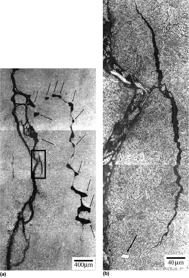
Fig. 21
(a) Micrograph showing cracks connecting shrinkage pores (indicated by arrows) in the internal component of the sample.
(b) Detail of the box in (a), where an inclusion is indicated by the arrow
164 / Failure Analysis of Heat Treated Steel Components
Name ///sr-nova/Dclabs_wip/Failure_Analysis/5113_151-176.pdf/Chap_05/ 18/8/2008 3:11PM Plate # 0 pg 164
In summary, to avoid the appearance of cold
joints in cast components, it is necessary to
control several man ufacturing stages of its
design; for example, prevent the component
from having regions with very thin thickness;
appropriate fusion and pouring temperatures for
each component; appropriate mold-filling
channel system; compatible pouring speed; and
well-established necessary amount of liquid
metal for filling the mold to avoid temporary
interruption in pouring.
Inclusions
Inclusions can be defined as nonmetallic and
sometimes intermetallic phases embedded in a
metallic matrix (Ref 16). Th ey are usually sim-
ple oxides, sulfides, or nitrides. In almost all
instances of metal casting, they are considered
to be detrimental to the performance of the cast
component. Sometimes, an intentional intro-
duction in larger quantities can lead to unique
dispersion-strengthened materials. There are
essentially two classifications for all inclusions:
Exogenous—those derived from external
causes
Indigenous—those that are native, innate,
or inherent in the molten metal treatment
process
Slag, dross, entrapped mold materials, and
refractories are examples of inclusions that
would be classified as exogenous. In most cases,
these inclusions are macroscopic or visible to
the naked eye at the casting surface. When the
casting is sectioned, they may also appear
beneath the external casting surface if they
have had insufficient time to float out or settle
due to the density differences with respect
to the molten metal. The presence of these
macroinclusions in steel castings is avoidable,
but their presence has plagued all forms of steel
casting and is particularly problematic in both
foundry processing and in the continuous cast-
ing of sheet steels and wire.
Macroinclusions are always practice related,
and analysis of the size and chemical composi-
tion of a macroinclusion can lead to the identi-
fication of potential sources of this problem.
Once an inclusi onal source is developed, a clear
and effective process change can be made to
eliminate such problems in the future. There-
fore, the techniques already developed by inte-
grated steel manufacturers can be readily
applied to foundries by coupling inclusion
identification with an in-dept h study of steel-
making and casting prac tices in the foundry.
Horwath and Goodrich (Ref 17) and Svoboda
et al. (Ref 18) have studied macroinclusions and
identified that these kind of inclusions can result
in excessive casting repairs or rejected castings.
To reduce these problems, a method was dev-
eloped to ensure that there are no inclusions in
cast materials above a size that results in failure
during ultrasonic or visual inspection of the
casting. In this method, the macroinclusions
should be eliminated; that is, inclusions greater
than 100 mm must be eliminated, but more
severely, inclusions greater that 50 mm should
be eliminated also.
Sulfides, nitrides, and oxides are examples of
indigenous inclusions that result from chemical
reactions of the molten metal and the local
environment. They are usually very small and
uniformly distributed inclusions, requiring
optical microscopy to visualize them. The pre-
sence of these microinclusions in castings is
generally unavoidable (Ref 9), because they
are the natural inclusions that are formed in
liquid steels due to the reaction between
alloying elements and oxygen; however, it is
necessary to minimize these inclusions as a
grain-boundary distribution of these inclusions
can be damaging to the component mechanical
properties.
Clean Steel
Clean steel is the common name attributed to
steel that has low levels of the elements sulfur,
phosphorus, nitrogen, oxygen, and hydrogen, as
well as residual ele ments copper, lead, zinc,
nickel, chromium, bismuth, tin, antimony, and
magnesium and almost no oxide product defects
produced during the act of steelmaking, ladle
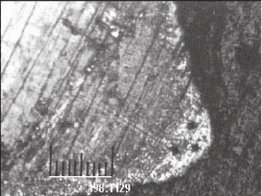
Fig. 22
Surface of a microfused component showing surface
decarburization
Failures from the Casting Process / 165
Name ///sr-nova/Dclabs_wip/Failure_Analysis/5113_151-176.pdf/Chap_05/ 18/8/2008 3:11PM Plate # 0 pg 165
metallurgy, casting, and rolling. Because the
“clean” concept is not absolute, the clean-
liness standard desired by the customer is con-
tinuously changing as a function of time and
technological improvements. The term clean
steel is therefore continually variable, depend-
ing on the application and the competition
between steel suppliers.
Thus, due to the variability of the term clean,
it is typical to refer to high-purity steels as steels
with low levels of solutes, and low-residual
steels as steels with low levels of impurities. For
example, there are high-purity, low-residual
clean steels, such as ultra-deep-drawing steel
sheets for automobiles, that require ultralow
carbon contents (530 ppm), low nitrogen con-
tents (530 ppm), and the absence of oxide
inclusions with diameters greater than 100 mm;
and there are low-residual clean steels, such as
those used for drawn and ironed cans, that are a
standard low-carbon steel (1006) without high-
purity component requirements but are ultra-
clean, with the requirement that oxide diameters
must be less than 20 mm. In addition, in forging
and bearing grades, there are clean steels that
require strictly controlled inclusion size dis-
tributions.
The total inclusion content related to the total
oxygen content has been correlated with bearing
life, and decreasing total oxygen contents
(below 10 ppm) improve the bearing life. In
addition to total oxygen content, the total length
of stringer inclusions after forging is also related
to the bearing life, and, at low total oxygen
levels, efforts to reduce inclusion cluste ring lead
to very long fatigue life for bearings.
Clean steels can be classified as steels with a
low frequency of inclusions (55 mm). The
major problems in clean steel manufacture are
incomplete separation of clustered solid inclu-
sions (45 mm in diameter), the presence of
sporadic larger liquid inclusions due to emulsi-
fication of covering slags, and the presence of
solid materials that originate from the refrac-
tories used to contain steels . The equipment used
to produce clean steel varies greatly between
different steel plants; however, current clean
steelmaking and casting practices are based on
the following principles:
The oxygen dissolved in liquid steel at the
melting stage must be transformed into a
solid or a gas and removed before casting.
The external oxygen sources that are res-
ponsible for the reoxidation of liquid steel
must be eliminated at every step in the
process.
The physical entrapment of the liquid fluxes
used during steel refining and casting must
be eliminated.
Refractories in contact with liquid steel must
be chemically stable and resistant to corro-
sion and erosion.
These simple principles are based on the
importance of maint aining chemical equilibrium
between the elements dissolved in liquid steel
and the slag and refractory systems that are in
contact with the liquid steel. Additionally, it is
necessary to control the fluid flow to avoid
conditions at liquid slag-steel interfaces that
could result in the physical entrapment of the
covering slag.
Clean steel manufacture is dependent on an
understanding of the fundamental steps neces-
sary to produce a clean steel:
Generation of the inclusion
Transport of the inclusion to an interface
Separation of the inclusion at the interface
Removal of the inclusion from the interface
The production of really clean steel depends of
the correct application of these principles.
The Formation of Macroinclusions
There are four major methods of forming
macroinclusions, and all problems occur during
foundry processing:
Reoxidation
Interaction between liquid steel and liquid
slags: vortexing, ladle or mold filling, argon
stirring, and pouring through a slag layer
Erosion/corrosion during steel pouring
Inclusion agglomeration due to clogging
during steel pouring
Reoxidation. The major cause of macro-
inclusion formation in casting is reoxidation
(Ref 17–19). To understand reoxidation, it is
necessary to understand that liquid iron is not
thermodynamically stable in the presence of
oxygen. The spontaneous reaction that occurs
results in the formation of iron oxide. As deoxi-
dizers are added, the steel remains unstable in
the presence of oxygen as a gas, but now the
inclusions that form include the oxides of the
deoxidants. Some deoxidants, such as alumi-
num, magnesium, and calcium, form very stable
oxides that are more stable than some slag and
166 / Failure Analysis of Heat Treated Steel Components
Name ///sr-nova/Dclabs_wip/Failure_Analysis/5113_151-176.pdf/Chap_05/ 18/8/2008 3:11PM Plate # 0 pg 166
refractory chemistries. Thus, the steel reacts
with the less stable oxides. Reoxidation can
occur by reaction with:
The ambient atmosphere (air)
The slag components less stable than the
oxide of the deoxidant
The refractories that are less stable than the
oxides of the deoxidant
Interaction between Liquid Steel and
Liquid Slag. Macroinclusion formation can
occur by emulsification of liquid slags or scums
on the surface of liquid steels. All of these types
of defects are practice related and can be solved
by practice changes. The issue in understanding
emulsification is to understand the source of the
energy that allows a buoyant droplet to become
submerged. Generally, this energy comes from
the interaction of a flowing steel stream and a
liquid slag. There are four major sources of this
energy:
Open stream pouring onto or through a
liquid slag (common during lip pouring)
Filling a ladle or mold at too high a fill rate in
the presence of slags or scums
Vortexing during steel pouring from a ladle
Steering in the ladle with gas at too high a
stir rate
Vortexing during drainage in a water model of
a ladle was studied by Sankaranarayanan and
Guthrie (Ref 20, 21). They showed that the
initial rotational velocity at the surface of the
vessel is extremely important in determining
the height at which the vortex will form, and that
increased rotational velocities caused increased
vortex initiation depth. Entrainment due to fluid
flow at the interface has been examined by
Noguchi et al. (Ref 22), who attempted to
decrease the entrainment of slag in low-carbon
titanium-aluminum-killed steels. They noted
that entrainment decreased as the casting speed
was decreased. In a study conducted by Naka-
mura et al. (Ref 23), it was found that defects that
contained mold slag increased in ultra-low-
carbon grades as the casting rate was increased.
They also reported using as low an argon flow
rate as possible in their submerged entry nozzles
to avoid entrainment. Manabu et al. (Ref 24)
have also documented the existence of a critical
gas flow rate for entrainment in both a silicon
oil-water and a slag-steel system. These authors
mention that the slag depth, slag properties, and
gas bubble diameter play a role. The oil depth
was found to be directly proportional to the flow
rate needed to cause entrainment. The gas bub-
ble size was found to be inve rsely proportional
to the flow rate needed to cause entrainment.
Manabu et al. (Ref 24), investigated the effect
of oil kinematic viscosities on emulsification
and found that although the kinematic viscosity
was varied by a factor of 10, very little change
was seen in the fluid velocity needed to cause
entrainment. Harman and Cramb (Ref 25),
documented the effect of interfacial tension and
slag viscosity on emulsification phenomena.
Erosion-Corrosion during Steel Pour-
ing. This kind of defe ct is usually associated
with the higher corrosivity of some steel grades,
because high manganese and grades that are
barely killed and have high soluble oxygen
contents attack the binder or the mold sand itself,
leading to large entrapped sand components.
Reoxidation of steel leads to FeO-based inclu-
sions that are very reactive and wet the materia ls
of the mold, leading to erosion of the mold in
areas of high fluid turbulence. Of course, sand
that is not pressed, sintered, or bonded in any
way can easily be entrapped in turbulent fluid
flow. Mold binders can also decompose at tem-
perature and release mold components that can
be entrapped. Expansion due to the high thermal
gradients associated with casting can also cause
sand to loosen.
Inclusion Agglomeration due to Clogging
during Steel Pouring. The formation of clogs
when steels containing solid inclusions are cast
can result in quite large macroinclusion defects
if the clogs are released during teaming. All
solid inclusions tend to agglomerate due to sur-
face tension effects. Clogging of pouring noz-
zles can be the source of large macroinclusion
defects when steels are dirty and pouring times
are long.
The Formation of Microinclusions
Microinclusions are formed due to reactions
between alloying additions and oxygen in mol-
ten steel. Their formation is generally hetero-
geneous or from highly supersaturated areas
during alloy addition. Due to the nature of the
formation of these inclusions (nucleation and
growth), they are generally small (less than
5 mm), unless they agglomerate due to turbu-
lence or grow under conditions of high oxygen
flux. In this study, microinclusions are defined as
those inclusi ons with diameters smaller than
20 mm. In addition, they are defined as having
Failures from the Casting Process / 167
Name ///sr-nova/Dclabs_wip/Failure_Analysis/5113_151-176.pdf/Chap_05/ 18/8/2008 3:11PM Plate # 0 pg 167
diameters greater than 1 mm. Table 5 show
typical microinclusions that are found in cast
steels.
Since microinclusions form due to a reaction,
they are driven by thermodynamics; therefore,
changing composition or temperature can lead to
their precipitation. This means they can form in
the ladle, during transport to the mold, or in the
mold during solidification.
Case Studies of Defects Caused
by Inclusions
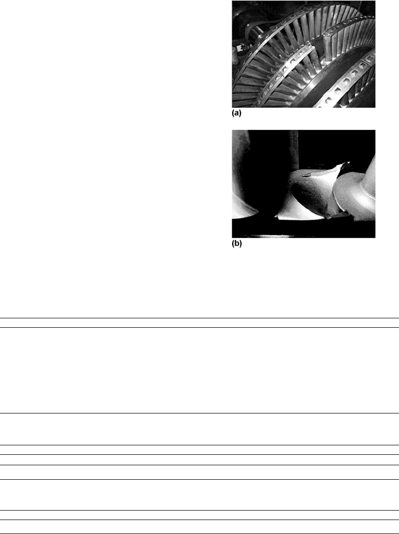
Failure of a Steam Turbine Rotor Blade.
Possible causes were investigated for failure of
a rotor blade of a 35 MW steam turbine. One of
the rotor blades was fractured after a certain
operation time (Fig. 23). The fracture occurred
at two different regions: at the bottom and at the
top extremity, near the metallic lashing strap.
Both regions have the highest stress concentra-
tion due to the blade geometry and loading
conditions. The blade fracture occurred during
the maximum turbine operation. The rotor was
working, with new blades mounted in between
harvests. The blades were manufactured with
steel ingots with the chemical composition pre-
sented in Table 6. The specifications for the
mechanical properties of the material at room
temperature are shown in Table 7.
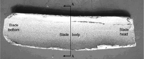
Figure 24 shows the fractured blade compared
to an intact one, with the fracture regions
indicated. Figure 25 shows a micrograph of the
fractured surface, near the blade bottom. Several
turning gear imprints can be observed, showing
the presence of multiple sites of crack nucleation
Table 5 Typical microinclusions found in cast steels
Steel type Microinclusion type Comments
Aluminum killed Alumina Formed in liquid steel after deoxidation
Manganese-silicon killed Manganese silicate or manganese-alumino
silicate
Formed in liquid steel after deoxidation
Calcium treated, aluminum killed Calcium aluminate Formed by reaction with alumina, liquid inclusion
Aluminum killed, with residual
magnesium
Magnesium aluminate Formed by reaction with alumina, solid inclusion
Titanium treated, aluminum killed Alumina, titania, titanium nitride Titania forms during reoxidation. Titanium nitride forms
during cooling, usually in the mold itself.
All steels Manganese sulfide Forms interdendritically during solidification. Often
nucleates on oxides already present in steels
Table 7 Mechanical properties specifications of FV520(B) steel
Yielding limit, MPa Strain limit, MPa Elongation, % Reduction in area, % Impact energy, J Hardness, HV
680–800 900–1050 20 min 55 min 40 min 270–320
Table 6 Nominal chemical composition of FV520(B) steel
Composition, wt%
CSiMnCrNiCuMoNbSP
0.07 max 0.7 max 1.0 max 13.2–14.7 5.0–6.0 1.2–2.0 1.2–2.0 0.2–0.5 0.06 max 0.03 max
Fig. 23
(a) Turbine stage that had the fractured blade.
(b) Detail of the fractured bottom component of
the blade
168 / Failure Analysis of Heat Treated Steel Components
Name ///sr-nova/Dclabs_wip/Failure_Analysis/5113_151-176.pdf/Chap_05/ 18/8/2008 3:11PM Plate # 0 pg 168
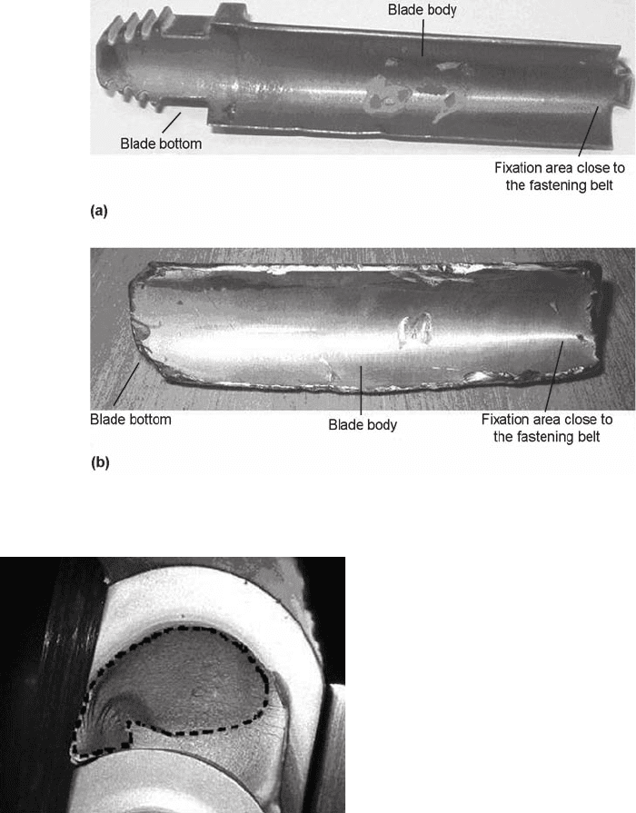
by fatigue. A darkened region is observed on the
fracture surface, indicated by the dotted line,
suggesting that this area was more exposed to
steam and high temperatures during the turbine
operation time, and it occupies a significant
component of the fracture surface.
Penetrating liquid analysis indicated the pre-
sence of secondary longitudinal cracks in the
fractured material, normal to the main crack, at
the bottom of the blad e. The analysis made in the
blade body indicated the presence of a large,
longitudinal crack, probably consisting of an
extension of the cracks observed at the bottom of
the blade, as shown in Fig. 26. Optical micro-
scopy analysis of a cross section of the blade
body revealed a different microstructure from
the martensitic steel matrix located parallel to
the longitudinal crack in the blade body.
Because of this different microstructure,
electron-dispersive x-ray (EDX) analyses were
carried out in the regions around the longitudinal
crack in the structural sample. They showed a
chemical composition different from the nom-
inal, as much for the central region as for the
blade head region. The fracture surface of the
longitudinal crack revealed a microstructure rich
in silicon, oxygen, manganese, and calcium,
suggesting that the material contains a large
number of impurities, probably slag from the
casting process and certainly introduced during
the manufacturing process of the component.
The occurrence of these impurities impedes
surface welding during the process of forging,
creating a surf ace with a smashed aspect.
However, the first region where the nuclea-
tion probably occurred was the one near the
Fig. 24 (a) Intact blade. (b) Fractured blade
Fig. 25
Micrograph of the blade fracture surface showing
several turning gear imprints and the oxidized area
(dotted line)
Failures from the Casting Process / 169
Name ///sr-nova/Dclabs_wip/Failure_Analysis/5113_151-176.pdf/Chap_05/ 18/8/2008 3:11PM Plate # 0 pg 169
longitudinal cracks detected by the penetrating
liquid. Indeed, the fractograph ic analysis of this
region shows a fracture morphology different
from the vicini ty, with several inclusion com-
ponents protruding into the fracture surface
(Fig. 27). The EDX microanalyses of these
components show a chemical composition with
a high level of carbon, which suggests that these
components are of iron carbide. Moreover,
several longitudinal cracks similar to the one
found in the blade body were observed.
Nonfusible longitudinal cracks exist along
the affected area in the blade. The large variety
of defects and the excessive mechanical vibra-
tion of the blade are probably the main causes of
crack nucleation by fatigue in the material near
the blade bottom. They culminated in the cata-
strophic fracture of the component.
The recommendation includes a more effi-
cient quality control of the manufacturing pro-
cess of the blade material and avoiding the
occurrence of casting defect formation, slag
inclusions, and other impurities.
Failure in the Axle of a Reduced Section in
a Rotating Component. Possible causes were
investigated for failure in the area of an inter-
mediate reduction. The rotating component
fractured completely after intermittent loading.
Figure 28 shows an outline of the component
and the axle region where the cracks developed.
The chemical composition (in weight percent) of
the fractured axle material is provided in
Table 8. The results show that the axle material
is a DIN-specified 17CrNiMo6 steel. The spe-
cifications of the material mechanical properties
at room temperature are given in Table 9.
The visual inspection of the fracture surface
(Fig. 29) indicated an extremely flat aspect, such
as the ones typically displayed in fatigue cracks.
The flat fracture surface occupied approximately
80% of the cross section (Fig. 29), exactly in the
axis of the radius change for the concordance
section. Due to the small relative section area of
the fracture axis, approximately 20% of its cross
section, it was deduced that the stress for the in-
service component was relatively low.
Ten measurements of Rockwell C hardness
were carried out, according to ASTM E18, on
the surface of the axle near the fracture region. A
mean hardness of 33.9 HRC was obtained. This
value is well below the expected one of 43 HRC.
Figure 30 shows the microstructure of steel in
the reduced section on a longitudinal cut plane in
the vicinity of fatigue crack nucleation. The
material presents a large amount of globular or
granular bainite, in agreement with the relatively
low value of hardness of the fractured axle
surface.
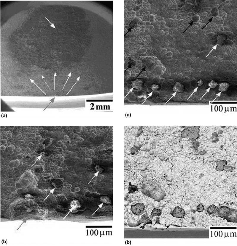
Figure 31(a) shows a general topview of the
fracture surface in the region where there was
fatigue crack nucleation, indicated by the arrow
at bottom. The five clustered arrows point in the
direction of fatigue crack propagation advance.
The arrow at the top shows a dark region, orig-
inated by contamination of the fracture surface
with oil or grease. Figure 31(b) shows in detail
the fatigue crack nucleating site that probably
started at an inclusion located exactly on the
circumference surface of the reduced section in a
region in the internal concordance radium. The
presence of some inclusions in the proximity
of the fracture site is pointed out by white arrows
in Fig. 31(b). Indeed, fractographic analysis
has shown the possibility of the existence of a
concentration of inclusions in the nucleation
region of the fatigue crack. Figure 32(a) con-
firms the high level of inclusions in the region,
indicated by white arrows, with signs of moving
Fig. 26
Longitudinal crack in the blade body revealed by penetrating liquid. The A-A section indicates the approximate position of
the cut made for structural observation.
170 / Failure Analysis of Heat Treated Steel Components
Name ///sr-nova/Dclabs_wip/Failure_Analysis/5113_151-176.pdf/Chap_05/ 18/8/2008 3:11PM Plate # 0 pg 170
by second-phase components indicated by black
arrows, similar to Fig. 31(b). Figure 32(b), the
same image shown in Fig. 32(a) but with back-
scattered electrons instead of secondary ones,
reveals the great amount of inclusions (darker)
in the metallic matrix (lighter). The chemical
analysis of the inclusions shows a massive
presence of aluminum, sulfur, and calcium
elements.
It is worth noting that these inclusions act,
on a microscopic scale, as metallurgical stress
concentrators. The presence of these second-
phase components especially near the external
axle surface where the maximum tensile stresses
are developed during a torsional load (and even
flexion) applied to the in-service component,
drastically reduces the lifetime in fatigue of the
rotating component. This happens through the
promotion of both mechanisms of nucleation
and fatigue crack propagation in their early
stages of growth.
It was concluded that crack initiation occurred
in the reducer axle by fatigue. A single crack
probably was nucleated on a nonmetallic inclu-
sion placed near the finish ed axle surface,
exactly in the internal component of the con-
cordance radius machined in the section change.
The combination of the effects of stress con-
centration generated by both discontinuities,
metallurgical (inclusion) and geometric (curva-
ture radius), created sufficient critical conditions
for fatigue crack nucleation that grew due to
the action of repetitive efforts of torsion (and
flexion) imposed in service to the rotating
component.
Failure of a 52100 Steel Axle. The raw
material (52100 steel) used in the manufacture
of an axle catastrophically fractured during
annealing heat treatment at 350
C. Figure 33
shows the fracture surface along with the cir-
cular cross section of the component (one of the
samples received for analysis). In the figure, the
arrow at left shows the main fracture plan e of
the axis (i.e., along a longitudinal plane), and
the arrow at right points to the starting point
of brittle fracture in its cross section. In Fig. 34,
this starting site is shown in detail (arrow at
bottom).
Figure 35 shows the microstructure of the
52100 steel, in the central region of the part in a
longitudinal plane, after etching with nital. The
massive presence of pearlite and the existence of
free cementite in both forms—globulized
(inside the pearlitic colonies) and veins (circling
the colonies)—is observed.
Figure 36 shows the vermiform dis-
continuities, with an appearance similar to
manganese sulfide inclusions, that are invariably
present in mechanical construction steels. The
presence of a grayish second phase, intermediate
to the metallic matrix (lighter) and the voids
Fig. 27
(a) General view of the probable initial region of
crack nucleation by fatigue crack. (b) Magnification
of the region in the box at the left in (a). (c) Magnification of the
region in the box at the right in (a)
Failures from the Casting Process / 171
Name ///sr-nova/Dclabs_wip/Failure_Analysis/5113_151-176.pdf/Chap_05/ 18/8/2008 3:11PM Plate # 0 pg 171
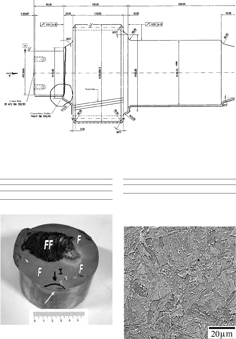
Fig. 28
Component drawing of the intermediate I axle. Highlighted are the section change region where the fracture developed and
the crack propagation path for the total fracture of the axle.
Fig. 29
Complete cross-sectional fracture surface of the
intermediate I axle. The white arrow shows the
nucleating site of the fatigue crack. The surface generated by
the fatigue crack propagation is identified by “F,” while the final
fracture of the remaining section is indicated by “FF.”
Fig. 30
Microstructure of the axle according to a long-
itudinal cut plane. Etched with 2% nital
Table 8 Chemical composition of the axle
material
Composition, wt%
CMnSiP SNiCrMo
0.17 0.63 0.23 0.10 0.011 1.45 1.59 0.30
Table 9 Mechanical properties at room
temperature
s
E
, MPa s
R
, MPa A
F
,% Q
F
,%
742 1080 20 57
172 / Failure Analysis of Heat Treated Steel Components
Name ///sr-nova/Dclabs_wip/Failure_Analysis/5113_151-176.pdf/Chap_05/ 18/8/2008 3:11PM Plate # 0 pg 172
(darker), is observed inside these dis-
continuities. This material component fills the
larger discontinuities, while the smaller dis-
continuities are almost totally filled by the sec-
ond phase.
Figure 37 shows that the most subtle dis-
continuities have a rather slim, cracklike aspect
and consequently present a great capacity
to concentrate high tensile stress es. In these
terms, it is possible to assume that these second
phases are potential crack nuclei, and that they
also generate a preferential path for crack
propagation. It is worth emphasizing that the
majority of these discontinuities were found
aligned in the direction of the thermomechanical
work to which the axle was submitted during its
manufacture (i.e., longitudinal direction). The
inclusions are disp osed on parallel planes to the
main fracture of the component during heat
treatment. This suggests the possibility that
these inclusions played a fundamental role in the
catastrophic failure of the 52100 steel axle.
Fig. 31
Fatigue crack site. (a) General view. (b) Detail. The
inclusion that originated the site was removed from
the fracture surface. SEM image with secondary electrons
Fig. 32
Concentration of inclusions near the fatigue crack
site. (a) SEM image with secondary electrons.
(b) Backscattered electrons
Failures from the Casting Process / 173
Name ///sr-nova/Dclabs_wip/Failure_Analysis/5113_151-176.pdf/Chap_05/ 18/8/2008 3:11PM Plate # 0 pg 173