Buschow K.H.J. (Ed.) Concise Encyclopedia of Magnetic and Superconducting Materials
Подождите немного. Документ загружается.


two extra hydrogen atoms occupying smaller 4R–3Fe
tetrahedral sites (Isnard et al. 1990).
This was confirmed by Koyama and Fujii (2000)
for N
2
Fe
17
N
3
. It is also of interest to analyze the cell
parameter expansion, not only on light element in-
sertion but also when other elements are substituted
for iron in order to modify the bond lengths. The
location of these elements as a function of their con-
centration provides interesting arguments for a better
understanding of the modification of the bulk mag-
netic characteristics that are volume dependent. This
has been systematized for titanium, cobalt, manga-
nese, gallium, silicon, etc., establishing reliable
schemes of substitution (Mishra et al. 1996).
For some resonantly absorbing elements (dyspro-
sium), either the use of a two-wall cylindrical sample
holder at l ¼12.5 A
˚
or the use of very short wave-
lengths (l ¼0.5 A
˚
) gives the most convenient condi-
tions to record rather good data on powdered
samples, e.g., gadolinium or samarium.
(b) Single-crystal diffractometry
The most precise technique to use for crystal struc-
ture determination is four-circle diffractometry.
However, this requires rather large single crystals.
Spheres of 1.5–2.5 mm in diameter of R
2
Fe
14
B
(R ¼Y, Nd, Ho, Er) have been cut by spark erosion
from large crystals and systematically studied by
neutron diffraction. Precise information about the
atomic positions and interatomic distances has been
obtained for these dense iron compounds (Wolfers
et al. 1996). Ancillary equipment can be used to per-
form experiments under special external conditions,
e.g., very low or high temperatures, uniaxial stress, or
high pressures.
(c) Small-angle and diffuse scattering
The small-angle neutron scattering (SANS) technique
using long neutron wavelengths (10–20 A
˚
) allows one
to investigate intermediate-size domains in the struc-
ture, for example, as formed by segregation effects.
Only a few examples using SANS have been reported,
e.g., the segregation rates of cobalt and copper in
Sm(Co–Cu)
5
alloys that markedly influence the in-
trinsic and extrinsic hard magnetic properties of the
binaries. In the RFe
5
Al
7
series, a clustering tendency
of iron is evident from classical powder diffraction
experiments by the analysis of diffuse scattering phe-
nomena, since the atomic clustering influences the
magnetic correlation scheme (Scha
¨
fer et al. 1994).
2.2 Magnetic Structure Determination
Neutron powder diffraction is a convenient technique
for the measurement of the local magnetic moment
characteristics. The higher the counting rate, the
better are the refined values. For such a purpose, an
instrument typically has a position-sensitive detector
(PSD) providing a high counting rate at a sufficiently
long wavelength that enables one to record the sig-
nificant magnetic source signal within the aperture of
the detector array. At HFR-ILL, Grenoble, and at
LLB, Saclay, there are optimized instruments allow-
ing one to measure diffraction patterns with a high
statistic in the time range of minutes up to a few
hours. It is recommended to record at least one high-
resolution diffraction pattern in a large range of Q
spacings using a dedicated diffractometer that pro-
vides precise crystal structure parameters. Moreover,
the excellent counting rate of the banana-type PSD
allows one to perform time- and temperature-
resolved experiments in order to determine accu-
rately the changes in the magnetic moments, e.g., for
R
2
Fe
14
B(R¼Nd, Ho, Er), as well as for RFe
12–x
T
x
(R ¼Dy) in the range of the Curie temperature or
possible spin reorientation temperatures (SRTs).
When single crystals are available, the four-circle
technique remains by far the best for detailed crystal
and magnetic structure determinations, as demon-
strated for the R
2
Fe
14
B series (R ¼Y, Nd, Ho, Er)
(Wolfers et al. 1996). After appropriate corrections
(e.g., absorption or multidomain corrections), precise
fittings to the data (several thousand recorded Bragg
peaks) lead to detailed pictures of almost ferromag-
netic but noncollinear magnetic structures accompa-
nied by the small-atom displacements (and crystal
symmetry lowering) related to the important magne-
toelastic forces existing in these compounds.
Another method, polarized neutron diffraction
(PND), can be used to investigate the magnetic struc-
ture of truly ferromagnetic and very large single
crystals, e.g., Y
2
Fe
14
B (Givord et al. 1985). With this
technique, and in the case where the data collection
statistics are good enough, a Fourier transformation
allows one to plot spin density projections, thus re-
vealing local but weak magnetic polarization effects
or temperature-induced changes of density moment
setting on cobalt atoms in ThCo
5
(Givord et al.
1977).
Using thermal neutrons it seemed impossible to
analyze the magnetic structures of one of the arche-
typal magnetic compounds, SmCo
5
. However, using
short wavelengths of 0.4–0.5 A
˚
, in order to reduce the
nuclear absorption, precise PND experiments have
allowed the calculation of the magnetic form factors
of cobalt and samarium, the latter being very differ-
ent at 4 K and 300 K: the samarium moment is much
smaller at room temperature than at low temperature
(Givord et al. 1979). Further analyses show that the
form factors of L and S type show quite different
radial shapes for samarium. Accounting for the op-
posite orbital and spin contributions in the magnetic
moment of samarium yields an anomalous thermal
behavior with a crossover temperature estimated as
350 K. Modeling of the appropriate Hamiltonian,
considering the large exchange forces and the mixed
1020
Permanent Magnet Materials: Neutron Experiments

CEF multiplets of the samarium ground state, allows
one to determine exchange and CEF parameters
from a fit to the experimentally obtained form
factors. Furthermore, the exchange field and the sec-
ond-, fourth-, and sixth-order CEF parameters have
been calculated, respectively, as 175725 K, 2007
50 K, 0750 K, and 50750 K (Givord et al . 1979),
which are in good agreement with values deduced
from magnetization experiments and corresponding
calculations.
For the parent compound YCo
5
, a PND study
has permitted the determination of the origin of a
very large magnetocrystalline anisotropy, which is
not related to the nonmagnetic yttrium but to one of
the two cobalt sites (Co
II
), which exhibits a partic-
ularly high orbital contribution and is attributed to
its peculiar and asymmetric environment (Schweizer
and Tasset 1980).
2.3 Magnetic Excitations
Dynamic excitation spectra have been recorded for
different series of intermetallics belonging to the dif-
ferent classes of hard magnetic materials. For the
R
2
Fe
14
B series of materials, inelastic neutron scat-
tering (INS) was first performed on powder samples
(Loewenhaupt et al. 1988). For R ¼Y and Ce, only
phonon scattering is identified. For R ¼Nd, Dy, and
Er, resonances of magnetic origin are observed. These
are attributed to magnon-like excitations for the lat-
ter two compounds, since they markedly increase
with temperature (dominant Zeeman field, negligible
CEF). For the neodymium compound, two well-
defined and equivalent peaks (22 meV and 36 meV)
are assigned to the two nonequivalent neodymium
sites in terms of CEF effects. From the thermal
dependence, it is concluded that the neodymium
moment corresponding to the larger CEF signature is
poorly affected by the SRT, contrary to the other
neodymium site that is sensitive to SRT conditions as
sharing the weakest CEF level. This approximate
model cannot be considered to agree well with the
accurate magnetic structure determination (Wolfers
et al. 1996) refined from single-crystal data collection.
Subsequent INS experiments on Nd
2
Fe
14
B single
crystals (Mayer et al. 1992) did not show the existence
of lines at 22–36 meV. However, low-energy lines
(magnon dispersion) were analyzed on the basis of
torque effects acting on the magnetic moments driven
by effective exchange and anisotropy fields. The
authors proposed a strong influence of long-range
interactions in relation to an itinerant character of
the iron magnetism.
The R
2
Zn
17
compounds are isotypic with the mag-
netic R
2
Co
17
compounds. However, owing to the
simplest magnetic situation (here only R is magnetic),
the CEF excitations were analyzed first (Garcia-
Landa 1994). In the low-energy region (o15 meV)
several peaks were confirmed to be of CEF origin;
then the noninteracting spins were described using
a pure CEF model. For R ¼Er, (T
SR
¼1.4 K,
T
N
¼1.6 K) a set of CEF parameters was determined,
of which the dominant one is the negative second-
order term of less than 2 K, thus agreeing with a
magnetically easy plane behavior.
Magnetic excitations have been investigated in de-
tail in some R
2
T
17
compounds (T ¼transition metal)
(Clausen and Lebech 1982). The spin wave dispersion
relationships have been interpreted with a linear spin
model comprising a Heisenberg exchange term and
single-ion CEF anisotropy terms. Experiments per-
formed on Dy
2
Co
17
single crystals using the IN8-ILL
spectrometer (Colpa et al. 1989) have been analyzed
using a complete Hamiltonian with respect to the
R–R exchange interaction, which is often considered
negligible if compared to the T–T and R–T ones.
Since there are some discrepancies between the as-
signment of a highly dispersive mode that is asso-
ciated with the Co–Co exchange forces, both the
exchange and the CEF characteristic energies have
been deduced. For Dy
2
Co
17
, the values are: J
TT
B
200 K, J
RT
B25 K, J
RR
B0.2 K, CEF
R
parameters
B28 to 6 K, and T-anisotropy parameter B6 K. They
are in good agreement with the high-field magnetiza-
tion fittings (Givord et al. 1977) as compared to those
obtained by NPD for SmCo
5
.
2.4 Atom Dynamics
The quasielastic neutron scattering (QNS) technique
based on space and time self-correlation of a single
nucleus, which is supposed to move within the com-
pound, is practically restricted to studying either the
motion processes of this nucleus (e.g., hydrogen) or
the fast rotation of some molecules. This becomes
possible owing to a very high incoherent scattering
length. For the present purposes, it can be used to
analyze the living time of a proton within interstitial
sites and the related energy of hopping. A typical ap-
plication could be the analysis of the diffusion mode
of protons, i.e., during either the hydrogen decrepi-
tation or the HDDR (hydrogen decomposition–
dehydrogenation–recombination) processes (diffusion,
nucleation, wall interface mechanisms, etc.) (see Mag-
nets: HDDR Processed). The analysis of the data
could be somewhat difficult owing to the rather large
unit cell and the multiple and different interstitial sites.
However, the questions concerning the diffusion
mechanisms have been partly solved, as explained
below.
2.5 Phase Transformation Analysis from Resolved
Diffraction Experiments
So far only structural and magnetic fundamental
trends of the main compounds forming magnet
1021
Permanent Magnet Materials: Neutron Experiments

materials have been considered. However, magnetic
properties are much improved by particularly fine-
designed microstructures resulting from well-defined
thermal or mechanical treatments. In situ neutron
diffraction experiments performed with PSD instru-
ments with high counting rates have allowed the de-
termination and optimization of chemical and
physical treatments leading to the best extrinsic prop-
erties. Some typical examples are given below.
Temperature- and time-dependent neutron diffrac-
tion experiments confirm the maximum hydrogen
uptake in the Nd
2
Fe
17
H
x
unit cell, and its distribu-
tion onto the two accessible sites (tetrahedral and
octahedral types). The preferential chemical attrac-
tion favors the larger and space repartited octahe-
drons (Isnard et al. 1990). The cell parameter
expansion is determined and the behavior of a crit-
ically short Fe–Fe distance is refined. A clear corre-
lation between the hydrogen occupation rates of
the sites is established, the corresponding changes of
the Fe–Fe distances and the nonlinear increase of the
Curie temperature have been attributed to an increase
of the exchange parameters.
Similar experiments performed with hydrides (de-
uterides were chosen to avoid the strong incoherent
scattering of hydrogen), as well as with carbides and
nitrides, allow the assertion of the existence of an
extended solid solution in the 2-17 and 1-12 hydride
and carbide phase diagrams and a two-phase be-
havior in nitrides (Fruchart et al. 1994).
Using a dedicated sample holder connected to a
hydrogen (deuterium) cylinder and gas pressure sen-
sors, time (kinetics), pressure level (or vacuum), and
temperature (slopes and plateaus) dependent neutron
diffraction experiments have been performed. For
example, they permit the analysis of the structural
aspects and the chemical phase transformations when
the HDDR route is applied. This process is one of the
most powerful ways to form a strongly coercive
microstructure in micrometer-sized powders as used
for bonded magnet technology (Liesert et al. 1997).
Neutron diffraction using PSD techniques is well
suited to reproduce the high-temperature thermal and
annealing treatments on real magnetic materials.
In situ experiments permit the correlation of known
dilatometric results with phase and structure trans-
formations in bulk materials. Finally, using a high
counting rate PSD, such as the D20 diffractometer at
ILL, one can extract significant crystal structure and
kinetic information in reasonable times even from
only a tiny amount of material (a few micrometers
thick), e.g., surface corrosion of material at moderate
temperature, under specific atmospheres.
2.6 Texture and Microstructure Analysis of Magnets
Cradle circle equipment can be used to analyze the
texture parameters (relative grain orientation of the
main phase). The orientation of the grains is a critical
parameter to form fully anisotropic magnets, thus
providing high levels of induction, i.e., large energy
products. Texturing of microcrystalline assemblies
can be achieved by using different routes depending
on the final state (use) of the magnet. The well-known
fully dense sintered magnets are treated at a high
temperature under high stress (see Magnets: Sinte-
red). A preferential orientation of isotropic micro-
crystalline particles can be achieved by die up-setting
and high-temperature fast forging (see Textured
Magnets: Deformation-induced).
Neutron diffraction texture analysis is a good tool
for examining the surfaces as well as the core of large
samples (sampling size of a few cubic millimeters)
after the material submitted to high stress. Different
types of magnetic material can be checked using tex-
ture analysis. Using this technique, it has been shown
for Nd–Fe–B materials, that fast forging at high
temperature is very efficient in order to align most of
the microcrystallite axes along the forging direction.
These axes are initially in-plane aligned as a result of
the book-mold procedure used during cooling the
magnet material (Rivoirard et al. 2000). Moreover,
the effectiveness of the metallurgical procedure is
correlated to a ductile-to-brittle phase transformation
and to rheological phenomena existing in the range
850–950 1C.
2.7 Laue and Reflectometry Methods
The white-beam technique of the Laue method
should be mentioned. Again, owing to the excellent
penetration ability of the neutron, the Laue method
can be efficiently used to analyze macro- and micro-
ordered materials. The first obvious use of a neutron
diffraction Laue setup is to control the quality and
the orientation of a single crystal within its full vol-
ume before other investigations (INS, PND, four-
circle, etc.). With one exposure many details of large
parts of the reciprocal space can be analyzed and ev-
idence of, for example, twins, defects, dislocations,
and strain fields can be obtained. The same method
has been used to determine the temperature, magnetic
field, and even pressure dependence of magnetic do-
mains up to the limit of resolution of the camera film,
i.e., a few micrometers (Tanner et al. 1992).
Because new materials are designed for integrated
purposes and the needs of densified media for re-
cording (e.g., using hard magnetic compounds), ma-
terials science is more and more concerned with
nanoscale samples. Neutron reflectometry is a very
interesting technique not only for providing informa-
tion on the quality of thin-layer samples (crystalline
and magnetic roughness) but also for analyzing the
interface magnetic coupling, the superstructure mag-
netic ordering reflecting the competition between
exchange forces, polarization effects via conduction
1022
Permanent Magnet Materials: Neutron Experiments

electrons, or large magnetocrystalline anisotropy of
interfaces. As the scattered signals are of nuclear or
magnetic origin, or both, the effectiveness of mag-
netic reflectometry takes advantage of polarized neu-
tron beams and polarization analysis techniques.
3. Conclusion
Scattering methods using thermal neutrons are par-
ticularly well suited to deliver unique information on
magnetic materials, and more particularly on those
expected to show potential as high-performance mag-
nets. Such magnetic materials are composed of tran-
sition and rare-earth metals, but often also contain
further elements in rather small amounts. The large
dimensional range (from electrons or orbitals to mi-
cro- and centimeter scales) can be treated using a very
wide range of powerful techniques. This allows not
only the characterization of static parameters, but
also of dynamics and excitation phenomena, thus ef-
fectively providing typical energies. Both aspects are
associated with the intrinsic quantities, such as mag-
netization, exchange forces, and CEF strengths.
Many extrinsic but critical quantities can also be
analyzed, especially those being relevant for chemical
procedures, processes, microstructure optimization,
etc. The multipurpose neutron scattering techniques
as such have no equivalent, especially because of their
efficiency in depth penetration, contrary to x-ray
techniques. Owing to the increasing neutron fluxes
and to the correspondingly improved detection tech-
niques, more and more detailed information can be
obtained. Hence, either microintegrated materials or
microstructured functional materials can be investi-
gated to satisfy the interest in these materials. It can
be very fruitful to combine the neutron investigation
methods as described here with more conventional,
laboratory-scale techniques to support the produc-
tion of new, hard magnetic materials.
See also: Crystal Field Effects in Intermetallic
Compounds: Inelastic Neutron Scattering Results;
Magnetic Excitations in Solids
Bibliography
Brown P J 1992 Magnetic form factors. In: Wilson A J C (ed.)
International Tables for Crystallography. Kluwer, London,
pp. 391–9
Clausen K N, Lebech B 1982 J. Phys. C: Solid State Phys. 15,
5095
Colpa J H P, Sinnema S, Frings P H, Franse J J, Radvanski R J
1989 J. Phys. Cond. Matter 1, 2047
Fruchart D, Isnard O, Miraglia S, Pontonnier L, Soubeyroux J
L, Fruchart R 1994 R
2
Fe
17
and RM
12
carbide and carbon-
itride synthesis from heavy hydrocarbon compounds. J.
Alloys Comp. 203, 157–63
Fruchart D, Wolfers P, Vuillet P, Yaouanc A, Fruchart R,
L’He
´
ritier P 1984 Structural and magnetic properties of
RE
2
Fe
14
B hydrides. In: Mitchell I V (ed.) Nd–Fe Permanent
Magnets: Their Present and Future Applications. CEC, Brus-
sels, Belgium, pp. 173–8
Garcia-Landa B 1994 Doctoral thesis. University of Zaragoza,
Spain
Givord D, Laforest J, Lemaire R 1977 Magnetic transition
in ThCo
5
due to change of Co-moment. Physica B 86–88B,
204–6
Givord D, Laforest J, Schweizer J, Tasset F 1979 J. Appl. Phys.
50, 2008
Givord D, Li H S, Moreau J M 1984 Solid State Commun. 50,
497
Givord D, Li H S, Tasset F 1985 Polarized neutron study of
the compounds Y
2
Fe
14
B and Nd
2
Fe
14
B. J. Appl. Phys. 57,
4100–2
Herbst J F, Croat J J, Pinkerton F E, Yelon W B 1984 Phys.
Rev. B 29, 4176
Isnard O, Miraglia S, Soubeyroux J L, Fruchart D, Stergiou A
1990 Neutron diffraction study of the structural and mag-
netic properties of the R
2
Fe
17
H
x
(D
x
) ternary compounds
(R ¼Ce, Nd and Ho). J. Less-Common Metals. 162, 273–84
Koyama K, Fujii H 2000 Nitrogen gas–solid reaction process
and basic magnetism of the interstitially modified rare-earth
3d transition-metal nitrides R
2
Fe
17
N
3
(R ¼Y, Ce, Nd, Sm)
and Y
2
Co
17
N
3
. Phys. Rev. B 61, 9475–93
Liesert S, Fruchart D, de Rango P, Soubeyroux J L 1997 The
hydrogenation–disproportionation—desorption–recombina-
tion process of Nd
2
Fe
14
B studied by in-situ neutron diffrac-
tion and thermomagnetic measurements. J. Alloys Comp.
253–254, 140–3
Loewenhaupt M, Prager M, Murani A P, Hoenig H E 1988
Inelastic neutron scattering on RE
2
Fe
14
B (RE ¼Y, Ce, Nd,
Dy and Er). J. Magn. Magn. Mater. 76–77, 408–10
Mayer H M, Steiner M, Stu
¨
sser N, Weinfurter W, Dorner B,
Lindga
˚
rd P A, Clausen K N, Hock S, Verhoef R 1992 Inelastic
neutron scattering measurements on Nd
2
Fe
14
B and Y
2
Fe
14
B
single crystals. J. Magn. Magn. Mater. 104–107, 1295–7
Mishra S R, Long G L, Pringle O A, Middleton D P, Hu Z,
Yelon W B, Grandjean F, Buschow K H J 1996 A magnetic
neutron diffraction, and Mo
¨
ssbauer spectral study of the
Ce
2
Fe
17–x
Al
x
solid solutions. J. Appl. Phys. 79, 3145–55
Rivoirard S, Fruchart D, de Rango P, de la Perrier B aˆ thie R,
Chateigner D 2000 Proc. 6th Int. Workshop on Rare-Earth
Magnets and their Applications. Sendaı
¨
, Japan
Scha
¨
fer W, Kockelmann W, Will G, Fischer P, Gal J 1994
Atomic distribution in RFe
x
Al
12x
compounds with R ¼Tb,
Dy, Ho, Er, Tm and Fe concentrations x l 5 studied by
neutron diffraction. J. Alloys Comp. 207, 316–20
Schweizer J, Tasset F 1980 J. Phys. F: Metal Phys. 10, 2799
Sears, V F 1984 AECL report 8490. Atomic Energy of Canada
Shoemaker D P, Shoemaker C B, Fruchart R 1984 The struc-
ture of a new magnetic phase related to the sigma phase: iron
neodymium boride Nd
2
Fe
14
B. Acta Crystallogr. C40, 1665–8
Tanner B K, Baruchel J, Abell J S 1992 Internal magnetic do-
main structure changes in thick TbAl
2
crystals revealed by
polarized neutron topography. J. Magn. Magn. Mater. 104,
317–8
Wolfers P, Obbade S, Fruchart D, Verhoef R 1996 Precise
crystal and magnetic structure determinations: I. A neutron
diffraction study of Nd
2
Fe
14
Bat20K.J. Alloys Comp. 242,
74–9
D. Fruchart
Laboratoire de Cristallographie du CNRS, Grenoble
France
1023
Permanent Magnet Materials: Neutron Experiments
Permanent Magnetic Devices in Otiatria
Inflammatory diseases of middle ear often result in
partial or complete destruction of its sound conduct-
ing elements: perforation of tympanic membrane,
damage to or destruction of ossicles (hammer, anvil,
stirrup) (Fig. 1; Kobrak et al. 1963, Wullstein et al.
1972, Williams and Rouf 1978, Ferris et al. 1998,
Kuvnetsov et al. 2001). This typically leads to signi-
ficant deterioration or complete loss of hearing.
Prosthesing of such miniature elements in a narrow
passage, while preserving the physiological level of
signal transduction and protecting the inner ear from
overloading, is a challenging task for the surgeon and
imposes rigorous requirements on materials for such
prostheses. Application of modern magnetic materi-
als such as SmCo
5
and NdFeB (see Rare Earth Mag-
nets: Materials and Magnets: Sintered) makes it
possible to manufacture miniature magnets with high
magnetic energy. These magnets can produce me-
chanical forces, typical for middle ear, even in mag-
netic systems with open magnetic circuits. A human
ear can hear sounds with intensities of up to 120 dB
(L ¼20 log(P/P
0
), where P
0
¼2 10
5
Nm
2
is the
audibility threshold, L is the sound intensity level).
So, the maximum sound pressure P on the tympanic
membrane can be estimated to be 20 N m
2
, and,
therefore, maximum forces in the middle ear do not
exceed 0.001–0.1 N. Such forces can be achieved by
permanent magnets with masses 0.01–10 g, which are
close to that of ossicles (several grams). These small
magnets can be produced in practically any size and
shape, be covered with biologically inert materials
and their magnetization can be precisely controlled.
Elastic magnets can also be manufactured (see
Magnets: Bonded Permanent Magnets). Thus, a vari-
ety of functional prostheses of middle ear elements
based on such miniature magnets can be created.
1. Tympanic Membrane Prosthesing
Tympanic membrane prosthesing in outpatients with
dry perforative otitis media can be achieved using
two thin sheets of a magnetic elastomer (rare-earth
alloy particles, embedded in a biocompatible plastic,
e.g., silicone). The prosthesing procedure includes in-
sertion of one compactly rolled sheet of the magnetic
elastomer through the tympanic membrane perfora-
tion into the inner ear cavity, where it is unfolded
using a special tool (S) (Dmitriev and Yunin 1988). A
second magnetic sheet is applied from the outer side
of the tympanic membrane. The two sheets attract
each other, sealing the perforation. This procedure
has lead to 15–25 dB improvement in hearing of 27
patients with two-sided dry perforative otitis media
and regeneration of tympanic membranes in two
patients.
2. Magnetic Prostheses of Ossicles
All known types of the ossicular implants form joint-
less junctions, which dramatically changes the middle
ear acoustic impedance. Permanent magnet-based
selforganizing prosthetic devices can preserve the
physiological mechanism of sound conduction in the
middle ear and simplify surgeons’ work. For exam-
ple, an anvil prosthesis consists of a horseshoe-
shaped ferromagnetic element inserted under the
stirrup arch and a magnet-containing stem, attached
either to the hammer or to the tympanic or artificial
membrane (Kuznetsov et al. 1983a, 1983b, 2001). The
two parts attach to each other by magnetic forces,
forming a slip-free magnetic junction between them,
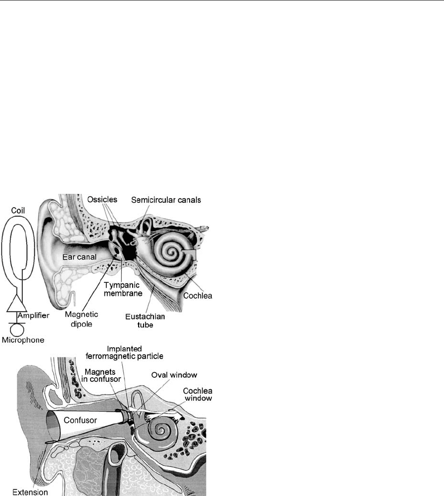
Figure 1
Main elements of a human ear and one of the schemes of
hearing rehabilitation using an implanted miniature
permanent magnet (top). The magnet is vibrated by an
external alternating magnetic field of sound frequency
and generates acoustic perceptions for the patient.
Application of a removable confusor in patients with
total absence of the middle ear sound conducting system
(bottom).
1024
Permanent Magnetic Devices in Otiatr ia

while the anvil-stirrup joint remains physiologically
flexible. Nonmagnetic elements of the prostheses are
made of rigid and light weight carbon fiber-based
materials. Flexibility of the construction prevents
overloading of the inner ear. Hearing improvement
(20–40 dB of sound conductivity) was observed in 25
of 30 patients with chronic suppurative otitis media,
who were implanted with anvil prostheses, and in 24
of 30 patients with stirrup prostheses (up to 35 dB).
Prostheses of ossicles with magnetic elements also al-
low to vibromassage the middle ear system by an ex-
ternal alternating magnetic field, preventing
immobilization of the prosthesis due to conjunctive
tissue formation.
3. Prosthesing of the Middle Ear Sound
Conducting System after a Radical Surgery
In patients with completely destroyed middle ear
sound conducting system, but an intact inner ear,
hearing rehabilitation requires both adjustment of the
prosthesis impedance with the impedance of the inner
ear and shielding of the round window. Magnetically
soft ferromagnetic particles (steel X13) were implant-
ed under the cicatrical tissue of oval window area in
postoperative patients with chronic suppurative otitis
media, impermeable auditory tube and total absence
of the sound conducting system (Kuznetsov et al.
1982, Palchun et al. 1982). A removable elastic con-
fusor, containing small permanent magnets, was at-
tached to the cochlea window by magnetic forces
(Fig. 1). This confusor focuses sound pressure on the
oval window while shielding the round window. Since
magnetic forces guide the confusor to the proper
position during insertion into the ear canal, this
procedure can be done by the patient. Confusor
prosthesing provided up to 35 dB decrease in air con-
duction thresholds in 18 patients, which is approxi-
mately two times better, than traditional techniques
such as shielding of the round window by oiled cot-
ton tampons or by silicone-based foam ‘‘otopen’’
(Wullstein et al. 1972, Williams and Rouf 1978).
4. Excitation of Acoustic Vibrations in the Middle
Ear Using Sound Frequency Alternating Magnetic
Field Action on a Magnetic Element in the Sound
Conducting System
Implantation of miniature permanent magnets into
nonmagnetic biological structures of middle ear
makes it possible to transform sound frequency al-
ternating magnetic fields into mechanical stimuli,
which can be perceived by the patient as acoustic
signals (Fig. 1; Kuzhetsov et al. 1983a, 1983b, 2001,
Dmitriev et al. 1986, 1988).
Many coils can generate suitable alternating mag-
netic fields, but a flat, spiral coil, concealed under
clothes on the patient’s shoulder appears to be the
most promising. It can generate a sound frequency
alternating magnetic field from 10
2
Oe to 10 Oe in
the ear cavity, providing adequate mechanical stim-
uli. Due to a relatively large distance from the coil to
the ear, the field in the ear cavity is practically uni-
form: rBE10
6
Oe cm
1
. The force F acting on the
magnetic moment m is proportional to rB:
F ¼(m r)B, while the torque M acting on the same
magnetic moment is proportional to H: M ¼m H.
Therefore, in such field a magnetic dipole will oscil-
late mostly tangentially. Elements of the middle ear
sound conducting system (ossicles, stirrup base) nor-
mally also move predominantly tangentially. Thus,
the movements of the magnet can simulate move-
ments of the ossicles in a normal ear and provide
acoustic stimuli for the patient.
Depending on the degree of the middle ear dete-
rioration, the location of the magnet varies: it can be
either glued to the remaining tympanic membrane, or
attached to ossicles (or be a part of an ossicle pros-
thesis), or implanted into the cicatrical tissue on the
oval window surface after a radical operation. The
latter was the most common technique and was used
in 11 patients. Biocompatible 5–50 mg SmCo
5
mono-
crystals were used. To increase the coercive force and
retentivity, the monocrystals were treated by a shock
wave before magnetization (Kuznetsov et al. 1977).
Significant rehabilitation efficiency in patients with
hearing thresholds of up to 70 dB was observed after
such operations. The patients were monitored for
several years and no negative effects of the magnets
or magnetic fields on the tissues and the processes in
the ear were detected.
Attaching a magnet to the tympanic membrane in
patients with an intact middle ear, but a reduced
sensitivity of the inner ear, and vibrating it with an
external alternating magnetic field can provide addi-
tional mechanical stimulation. Extensive experimen-
tal studies were done on cadaver material to optimize
the magnet size to provide a natural level of sound
pressure on the tympanic membrane. Optimal mag-
net size was found to be 56 mg (Dmitriev and
Aknesov 1992). This technique provides a significant
improvement of sound perception for all tested mag-
net locations and solves cosmetic problems of hearing
rehabilitation (no wires, earpiece).
5. Magnetically Controlled Implantable Devices
for Restoration of Inner Ear Function in Me
´
nie
`
re’s
Disease Patients
Me
´
nie
`
re’s disease (labyrinth hydrops) is a serious in-
ner ear disease, characterized by an increase of the
hydrostatic pressure of intralabyrinth fluids, leading
to irreversible destruction of hearing and vestibular
functions. This ailment is treated by draining the
excess endolymph from the labyrinth to normalize
1025
Permanent Magnetic Devices in Otiatria

the pressure using several types of implantable drain-
age devices, thus eliminating vertigo and preserving
the remaining hearing level (Kobrak 1963).
Unfortunately, opening thresholds of these devices
cannot be adjusted after implantation and the pres-
sure in the labyrinth cannot be maintained at the
level, optimum for the particular patient. Two types
of implantable magnetic valves for draining endo-
lymphatic sack were developed and tested (Kuznet-
sov et al. 1985, Yunin et al. 1984). Core elements of
the valves are rare-earth permanent magnets and
magnetic elastomers. Different compositions of mag-
netic particles (barium hexaferrite and/or rare-earth
alloys) imbedded in silicone enable to create el-
astomers with a wide variety of magnetic properties.
Magnetic elastomers were attracted to each other or
permanent magnets and closed the endolymph out-
flow. The devices were grafted into the inner ear of
the patients. During an attack, a postoperative pa-
tient can open the type I valve and decrease the
endolymph pressure by bringing a magnet close to
the implanted valve. Once the magnet is removed, the
valve closes. Type II valves open automatically when
the endolymph pressure exceeds a certain threshold.
The valve opening threshold can be adjusted after
grafting of the device by changing magnetization of
the elastomer using an external impulse magnetiza-
tion device. Thus, a physician can optimize the endo-
lymph pressure for each particular patient and adjust
it to a comfortable level in response to the patient’s
condition without surgery. Elastomers in the valves
can be vibrated by external alternative magnetic field,
preventing clogging of the valve due to conjunctive
tissue formation and allowing active pumping of
endolymph if necessary.
Six patients were implanted with type I valves, and
another five received type II valves. The patients were
monitored for more than seven years and demon-
strated stable improvement in their condition: vertigo
attacks were controlled by the valves, hearing levels
were maintained. The patients were able to work and
live normal lives.
6. Concluding Remarks
A variety of implantable prostheses of middle ear
structures based on permanent magnets and using
magneto-mechanical forces for their operation were
developed for treating middle ear ailments and hear-
ing rehabilitation. Methods of surgical application
of the devices were developed and in clinical trials
more than 85% of 127 patients with different degrees
of middle ear system degradation have shown stable
improvement. This promising technology increases
reliability of functional results, but needs further de-
velopment and approval of regulatory authorities
(FDA, etc.) for wider clinical trials and use.
Bibliography
Dmitriev N S, Aknesov Yu A 1992 Principle measurement
scheme of transductional properties of permanent magnets.
Current Problems of Clinical Otolaryngology. Irkutsk, Russia,
p. 355
Dmitriev N S, Yunin A M 1988 USSR Patent 1421332
Dmitriev N S, Yunin A M, Kuznetsov A A 1986 USSR Patent
1237170
Ferris P, Prendergast P J, Rice H J, Blayney A W 1998 Finite
element modeling of prostheses for ossicular chain recon-
struction. J. Biomech. 31, 130
Kobrak H G 1963 Middle Ear. Medicina, Moscow
Kuznetsov A A, Nikiforov A K, Adadurov G A, Mishin D D
1977 Magnetic Properties of SmCo
5
monocrystals Subjected
to Shock waves. Izvestia Visshih Uchebnyh Zavedenii (Phys-
ics) 5, 137–9
Kuznetsov A A, Dmitriev N S, Palchun V T, Yunin A M 1982
USSR Patent 950374
Kuznetsov A A, Dmitriev N S, Yunin A M 1983a USSR Patent
1076114
Kuznetsov A A, Dmitriev N S, Yunin A M, Kazakova Z I
1983b USSR Patent 1041110
Kuznetsov A A, Yunin A M, Palchun V T, Dmitriev N S 1985
USSR Patent 1159572
Kuznetsov A A, Yunin A M, Dmitriev N S, Palchun V T 2001
Applications of Magnetic devices in otiatria. JMMM 225,
202–8
Palchun V T, Dmitriev N S, Kuznetsov A A, Yunin A M 1982
USSR Patent 971287
Williams D F, Rouf R 1978 Implants in surgery. Medicina,
Moscow
Wullstein H L 1972 Hearing Improvement Operations. Med-
icina, Moscow
Yunin A M, Kuznetsov A A, Palchun V T, Dmitriev N S 1984
USSR Patent 1151141
A. A. Kuznetsov, N. S. Dmitriev, M. Yunin,
A. Savichev and O. A. Kuznetsov
University of Missouri at Columbia, USA
Permanent Magnets: Corrosion Properties
The rare-earth permanent magnets, particularly Nd–
Fe–B magnets, possess outstanding magnetic prop-
erties and therefore have grown rapidly in production
(see Rare Earth Magnets: Materials; Magnets: Sinte-
red). However, their poor corrosion resistance
(Jacobson and Kim 1987) has limited their applica-
tions. This article discusses the corrosion mechanism
of Nd–Fe–B magnets and methods to improve their
corrosion resistance.
1. Corrosion Mechanism
Permanent magnets based on Nd–Fe–B are very sen-
sitive to various corrosive environments. The great
sensitivity to corrosion is caused by the considerable
amount of rare-earth element in their composition,
1026
Permanent Magnets: Corrosion Properties
since the electromotive forces of rare-earth elements
are much larger than those of iron. Normally, Nd–
Fe–B magnets consist of three phases: (i) the main
Nd
2
Fe
14
B phase; (ii) a neodymium-rich (usually
Nd
4
Fe) phase, and (iii) a boron-rich phase. From
the electrical point of view, such a contact of three
different metallic phases with great differences in
electrochemical activity must promote rapid corro-
sion. Nakamura et al. (1989) measured the electrode
potentials of the different phases in 1 N HCl solution.
Because the Nd-rich phase has a much lower elec-
trode potential than the Nd
2
Fe
14
B phase, a selective
corrosion of the Nd-rich phase occurs by forming a
local cell between the Nd
2
Fe
14
B and Nd-rich phases.
Therefore, the grain boundary phase corrosion is
dominant rather than uniform corrosion for sintered
Nd–Fe–B magnets, a fact made evident by micro-
structural observation. The corrosion rate decreases
as the Nd content (or volume fraction of Nd-rich
phase) decreases. On the other hand, with the increase
of cathodic polarization in strong acid, the hydrogen
reduction reaction produces hydrogen atoms at the
cathode that can diffuse into the base metal and cause
embrittlement, and therefore the rate of Nd–Fe–B
magnet dissolution increases (Bala and Szymura
1991). The abnormal dissolution (mechanical degra-
dation) rate increases linearly with the square root of
the hydrogen evolution current density.
Since the Nd–Fe–B magnets are generally used in
atmospheric environments, various accelerated cor-
rosion environment tests were employed in order to
predict the service life of the magnet in ambient en-
vironments. The accelerated corrosion environments
include: hot–dry air, hot–humidity, high-pressure
steam, and salted spray.
The kinetics of oxidation of Nd–Fe–B alloy mag-
nets in air at elevated temperatures (80–200 1C) ex-
hibit an exponential weight gain (Turek et al. 1994,
LeBreton and Teillet 1990). Quick initial oxidation
of the intergranular Nd-rich phases is followed by
oxidation of the Nd
2
Fe
14
B phase. The oxidation
products are Nd
2
O
3
, NdFeO
3
,Fe
3
O
4
, and an inho-
mogeneous phase close to a-Fe.
When Nd–Fe–B magnets are exposed to a hot–
humid environment (50–90 1C, 50–90% relative hu-
midity) (LeBreton and Teillet 1990), the magnet is
disintegrated but the Nd
2
Fe
14
B phase is generally
unaffected. The oxidation occurs in the Nd-rich re-
gion, producing Nd
2
O
3
and Nd(OH)
3
as is evidenced
by x-ray diffraction. This disintegration increases as
temperature and relative humidity increase.
A more accelerated corrosion test is carried out in a
high-pressure steam vessel (McGuiness et al. 1994,
Kim et al. 1996). In an autoclave (or PCT) test, grains
of the Nd
2
Fe
14
B phase have fallen apart from the
magnet. X-ray diffraction patterns on the loose par-
ticles exhibit mainly Nd
2
Fe
14
B peaks with small
Nd(OH)
3
peaks indicating that the oxidation product
is Nd(OH)
3
and the Nd
2
Fe
14
B remains unspoiled.
Macroscopic disintegration was observed on both
magnetic pole faces of the magnetically aligned and
sintered Nd–Fe–B magnet after exposure to an auto-
clave environment at 115 1C and 2 bar, which is sim-
ilar to the conditions of hydrogen decrepitation of the
magnet. The microstructure underneath the disinte-
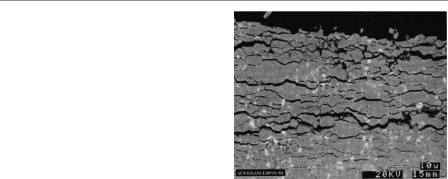
gration surface shows plate-like cracking perpendic-
ular to the magnetic orientation as shown in Fig. 1.
The microstructure of hydrogen-decrepitated sam-
ples shows similar cracking patterns. There is un-
doubtedly anisotropic corrosion and hydrogen
decrepitation behavior in anisotropic Nd–Fe–B mag-
nets. The similarity between these two corrosion
processes infers a common corrosion mechanism. As
described before, the hydrogen evolution during ca-
thodic polarization of Nd–Fe–B in strong acid causes
mechanical degradation (abnormal dissolution), and
thus hydrogen decrepitation is involved and plays an
important role in the corrosion mechanism. Hydro-
gen may be generated in the autoclave test from the
decomposition of water vapor:
3H
2
O þ Nd-NdðOHÞ
3
þ 3H
Thus, the corrosion mechanism for Nd–Fe–B mag-
nets in the heat and humidity of the autoclave test
starts with a surface reaction of water vapor with the
Nd-rich grain boundary phase. The generated hy-
drogen atoms diffuse along the grain boundaries into
the interior of the magnet. Some of the hydrogen re-
acts with the Nd-rich grain boundary phase, causing
volume expansion of this phase (3H þNd -NdH
3
)
and the rest goes into the Nd
2
Fe
14
B matrix (xH þ
Nd
2
Fe
14
B-Nd
2
Fe
14
BH
x
). The corrosion product of
Nd
2
Fe
14
B characterized by x-ray diffraction reveals
that a significant expansion of the lattice has taken
Figure 1
SEM micrograph of a Nd–Fe–B magnet subjected to an
autoclave test (Kim et al. 1996).
1027
Permanent Magnets: Corrosion Properties
place (McGuiness et al. 1994). Volume expansion of
the Nd-rich phase and lattice expansion of the
Nd
2
Fe
14
B phase results in the removal of the
Nd
2
Fe
14
B matrix phase grains. The subsurface cracks
provide the path for reacting species (water vapor) to
the inside of the Nd-rich phase, which accelerates the
corrosion reaction. This corrosion reaction increases
as the amount of Nd-rich phase in the Nd–Fe–B
magnet increases.
2. Improvement of Corrosion Resistance
As discussed in Sect. 1, the large difference in the
electrochemical potential between the Nd-rich and
Nd
2
Fe
14
B phases promotes a rapid corrosion reac-
tion. The grain boundary also provides the diffusion
path of reacting species such as hydrogen atoms. Im-
provement of corrosion resistance can therefore be
achieved by increasing the electrode potential of
the Nd-rich phase as close as possible to that of the
Nd
2
Fe
14
B phase and by minimizing the Nd-rich
region.
Partial substitution of iron by cobalt is reported
substantially to improve the corrosion resistance by
forming the Nd
3
Co phase in the Nd-rich grain
boundary, particularly in a hot–humid environment
(Tokunara and Hirosawa 1991, Kim and Camp
1996). The electrode potential of Nd
3
Co is higher
than that of the Nd
4
Fe phase and is close to the
Nd
2
Fe
14
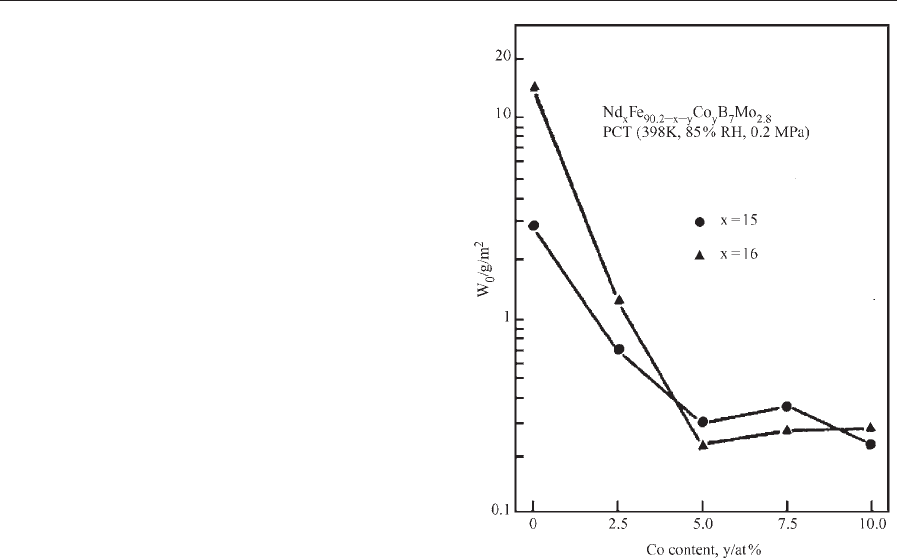
B phase (Nakamura et al. 1989). The corro-
sion rate of Nd–Dy–Fe–Co–B–Mo sintered magnets,
as monitored by weight loss in PCT, is shown in
Fig. 2. This corrosion rate decreases as the cobalt
content increases to 5 at.% Co.
It is noted that a cobalt addition by itself deteri-
orates the coercivity although it improves the corro-
sion resistance and Curie temperature. Therefore,
various additional elements combined with cobalt
were investigated in order to compensate for the neg-
ative effect of reducing coercivity by cobalt. Elements
including Al, Ga, Cu, Sn, Cr, Zr, Nb, V, Mo, or W
combined with Co are found to increase the co-
ercivity. Because of these additions, the corrosion re-
sistance is further improved. Particularly, a combined
addition of cobalt and copper substantially improves
both the corrosion resistance and the coercivity with-
out reduction of the energy product (Kim and Camp
1996).
Nickel or Ni and Co additions are also reported to
improve significantly the corrosion resistance (Bala
et al. 1990). The segregation of nickel to the inter-
granular Nd-rich phase would reduce the electro-
chemical difference among the phases yielding good
corrosion resistance. It is noted, however, that a
nickel addition deteriorates coercivity and reduces
the Curie temperature. A further small addition of
titanium in a Nd–(Fe,Co,Ni)–B alloy enhances the
coercivity to a moderate level. Vanadium or molyb-
denum additions were also reported to improve co-
ercivity and corrosion resistance by forming
intergranular precipitates (Fe–M
2
-B
2
), but at the
expense of the energy product (Hirosawa et al. 1990).
A partial replacement of Nd by dysprosium or
terbium in Nd–Fe–B magnets also improves the cor-
rosion resistance. The lowering of the total rare-earth
amount in Nd–Fe–B magnets increases the volume
fraction of the Nd
2
Fe
14
B phase and thus raises the
electrode potential, which improves the corrosion re-
sistance (Tokunara and Hirosawa 1991). Chromate
etching on the surface of the magnet dissolves the
Nd-rich surface phase. This eliminates the reaction
site, which also improves the corrosion resistance
(Kim 1989).
In addition, increasing density and minimizing po-
rosity also improves the corrosion resistance. The
corrosion current reportedly increases as the porosity
increases in the magnet. A vacuum impregnation of
the surface porosity was reported to improve the
corrosion resistance (Stevenson and Stevenson 1988).
The microstructure of Nd–Fe–B magnets also affects
their corrosion behavior. Nanostructured melt-spun
ribbons exhibit a uniform corrosion, while the sinte-
red magnets exhibit a localized corrosion of the
Figure 2
Weight loss per unit area of uncoated magnets in PCT
for 130 ks as a function of cobalt content (Tokunara and
Hirosawa 1991).
1028
Permanent Magnets: Corrosion Properties

Nd-rich grain boundary phase (Nakamura et al.
1989). The latter has a lower electrode potential
and thus a poorer corrosion resistance. Hot-worked
Nd–Fe–B magnets also exhibit better corrosion resis-
tance than the sintered magnets (Nozieres and Taylor
1990).
A postmachining heat treatment of Nd–Fe–B sin-
tered magnets at 600–1000 1C in a vacuum or in a
very low oxygen environment formed a very thin
oxidation layer on the surface and thus improved the
corrosion resistance in hot–humid environments
(Imaizumi et al. 1987).
3. Corrosion Protection
The corrosion resistance is further improved by ap-
plying corrosion protection layers on the surface of
the magnet (Mitchell 1990). Various depositing ma-
terials can be put on the magnet surface by using
various techniques. Plating can be described as the
deposition of a material from a solution. There are
two main types of plating: one is electrolytic or elect-
roless plating and the second is electropainting. The
most common coating is electrolytic or electroless
plating of Ni, Sn, Cu, or combinations of these, be-
cause of ease of mass production, economic process,
and durability.
However, an adjusted pretreatment to inhibit a re-
action of nickel with the magnet is needed because
Nd–Fe–B magnets may absorb hydrogen during the
plating process causing cracking and, thus, failure of
adherence of the layer to the magnet. Nickel plating
usually exhibits a good corrosion resistance in hot–
humid environments but a poor resistance in salt-
spray environments. The cathodically deposited elect-
ropaint coating is also very popular because of its
ease for mass production. The electropaint coating
usually exhibits an excellent corrosion resistance in
salt-spray environments and a moderate resistance in
hot–humid environments.
Vapor deposition generally refers to the deposition
of a material on to a substrate by use of the gaseous
phase of the depositing material. There are several
forms of vapor deposition as physical, chemical, and
spray deposition. Among them the aluminum-ion
vapor deposit coating is important for achieving a
high corrosion resistance. It provides the highest de-
gree of protection against hot–humid environments
and exhibits a moderately good resistance to salt-spray.
See also: Magnets: High-temperature; Magnets:
Remanence-enhanced
Bibliography
Bala H, Szymura S 1991 An electrochemical investigation
of dissolution of Nd–Fe–B magnets in acid-solution under
cathodic polarization. Corros. Sci. 32, 953–63
Bala H, Szymura S, Wyslocki J J 1990 Corrosion characteristics
of Nd
2
Fe
14x
Ni
x
B permanent magnets. IEEE Trans. Magn.
26, 2646–8
Hirosawa S, Tomizawa H, Mino S, Hamamura A 1990 High-
coercivity Nd–Fe–B-type permanent magnets with less dys-
prosium. IEEE Trans. Magn. 26, 1960–2
Imaizumi N, Inoue N, Takahashi K 1987 Effects of post-
matching heat treatment on the magnetic properties and the
corrosion of NdFeB magnets. IEEE Trans. Magn. 23, 3610–2
Jacobson J, Kim A 1987 Oxidation behavior of Nd–Fe–B mag-
nets. J. Appl. Phys. 61, 3763–5
Kim A S 1989 J. Mater. Eng. 11,95
Kim A S, Camp F E 1996 High performance NdFeB magnets.
J. Appl. Phys. 79, 5035–9
Kim A S, Camp F E, Lizzi T 1996 Hydrogen induced corrosion
mechanism in NdFeB magnets. J. Appl. Phys. 79, 4840–2
LeBreton J M, Teillet J 1990 Oxidation of (Nd,Dy)FeB per-
manent magnets investigated by
57
Fe Mossbauer spectro-
scopy. IEEE Trans. Magn. 26, 2652–4
McGuiness P J, Fitzpatrick L, Yartys V A, Harris I R 1994
Anisotropic hydrogen decrepitation and corrosion behavior
in NdFeB magnets. J. Alloy Comp. 206, L7–10
Mitchell P 1990 Corrosion protection of NdFeB magnets. IEEE
Trans. Magn. 26, 1933–5
Nakamura H, Fukuno A, Yoneyama T 1989 In: Proc. 10th Int.
Workshop on Rare Earth Magnets and their Applications.
Kyoto, Japan, p. 315
Nozieres J P, Taylor D W 1990 Corrosion resistance of hot-
worked NdFeB permanent magnets. J. Less-Com. Metals.
162, L1–5
Stevenson M, Stevenson J Jr 1988 Metal Finishing 86,93
Tokunara K, Hirosawa S 1991 J. Appl. Phys. 79, 5521
Turek K, Liszkowski P, Figiel 1994 The kinetics of oxidation of
Nd–Fe–B powders. IEEE Trans. Magn. 29, 2782–4
A. S. Kim
JAHWA Electronics Co., Ltd., Choong-Book
Korea
Permanent Magnets: Microstructure
The microstructure of rare earth permanent magnet
materials is defined by the type, the structure and the
number of phases, by the size, shape and the topo-
logical arrangement of the individual phase regions
and their interfaces, and by the type, structure and
geometry of lattice defects. In the following, several
examples of TEM micrographs will show the differ-
ences between various types of rare earth magnets
(see Rare Earth Magnets: Materials). The importance
of newly developed permanent magnetic materials
in many electro-, magnetomechanical and electronic
applications can be attributed to the drastic improve-
ment of microstructure related properties, such as
the magnetic energy density product and the coercive
field.
The rare earth intermetallic phases with a high
uniaxial magnetocrystalline anisotropy (see Magnetic
1029
Permanent Magnets: Micro structure