Burton T. (et. al.) Wind energy Handbook
Подождите немного. Документ загружается.


with consequent potential cost benefits. The hinge eliminates the transfer of out-of-
plane aerodynamic moments from the rotor to the low-speed shaft, resulting in
large reductions in the operational loadings on the shaft, nacelle and yaw drive.
The dependence of these loads on rotational speed is also largely removed, with the
result that the optimum rotational speed for a two-bladed machine in energy cost
terms is increased, approaching the value giving maximum energy yield.
Although teetering provides scope for significant cost saving s on the shaft,
nacelle and yaw drive (which account for nearly 20 percent of the baseline machine
cost), these savings are offset by the additional costs associated with the teeter hinge
and teeter restraint system.
6.5.4 Effect of number of blades on loads
Moment loadings on the low speed shaft and nacelle structure from three-bladed
and rigid-hub two-bladed machines were examined in Sections 5.10 and 5.11, and
are compared in Table 6.6 below for machines of the same diameter and rotational
speed. The stochastic loading comparison is based on a turbulence length scale to
rotor diameter ratio of 1.84.
It is seen that loadi ngs from a rigid-hub two-bladed rotor are significantly larger
than from a three-bladed rotor. However, in most two-bladed machine designs, the
rotor is allowed to teeter instead of being rigidly mounted, with the result that
aerodynamic moments on the shaft and nacelle structure quoted in Table 6.6 are
eliminated, and the blade out-of-plane root bending mo ments are reduced. The
benefits and drawbacks of teetering the rotor are examined in Section 6.6.
The rotor thrust variatio ns at blade passing frequency due to stochastic loading,
which are a dominant factor in tower fatigue design, are very similar for two- and
three-bladed machines rotating at the same speed. However, two-bladed machines
usually rotate faster than three-bladed machines of the same diameter, so the cyclic
rotor thrust variations are higher.
Table 6.5 Comparison of Two-bladed Design Variants Utilizing the Same Blades with 40 m
Diameter, 500 kW Three-bladed Baseline Machine
Variant Rotational
speed
(r.p.m.)
Rated
power
(kW)
Annual
energy
yield
(MWh)
Reduction in
annual energy
yield compared
with baseline
machine
Tower cost
governed
by
Reduction
in overall
machine
cost
Increase/
reduction
in cost of
energy
(a) 30 331 1054 19% Fatigue
loading
16% þ4%
Extreme
loading
20% 1%
(b) 35.4 500 1256 4% Fatigue
loading
1% þ3%
Extreme
loading
7% 3%
NUMBER OF BLADES 345

6.5.5 No ise constraint on rotational speed
As noted in Section 6.5.3, there may be significant cost benefits to be gained from a
two-bladed design with increased rotational speeds, because, in addition to the
blade saving, the cost of the whole of the drive train is reduced because of the
reduced torque. However, as noted in Section 6.4.2, it is normal to restrict tip speed
to about 65 m/s in order to limit aerodynamic noise emission. At 62.8 m/s, the tip
speed of the baseline machine discussed in Section 6.5.3 is within this limit, but the
tip speed of option (b) of 74 m/s would be less likely to be acceptable, except at
remote sites or offshore. This subje ct is considered further in Section 6.9.
6.5.6 Visual appearance
Although the assessment of visual appearance is essentially subjective, there is an
emerging consensus that three-bladed machines are more restful to look at than
two-bladed ones. One possible reason for this is that the apparent ‘bulk’ of a three-
bladed machine changes only slightly over time, whereas a two-bladed machine
appears to contract down to a one-dimensional line element, when the rotor is
vertical, twice per revolution. A secondary factor is that two-bladed machines
generally rotate faster, which an observer can also find more disturbing.
6.5.7 Single-bladed turbines
Apart from the saving in rotor cost itself, the single-bladed turbine concept is an
attractive one because of the reduction in drive train cost realizable through
increased rotational speed (Section 6.5.2). An obvious disadvantage is the resulting
Table 6.6 Comparison of Loads on Shaft and Nacelle for Three-bladed and Rigid-hub Two-
bladed Machines
Deterministic loading arising from wind
shear and/or yaw misalignment, in terms of
blade root out-of-plane bending moment
amplitude, M
o
Stochastic loading
Location of moment
loading
Three-bladed
machine
Rigid-hub two-bladed
machine
% increase for rigid-hub
two-bladed machine
compared with three-
bladed machine
Shaft bending
moment
amplitude
1.5 M
o
2 M
o
22%
Nacelle nodding
moment
1.5 M
o
M
o
(1 þ cos 2ł) 22%
Nacelle yaw
moment
Zero M
o
sin 2ł 22%
346
CONCEPTUAL DESIGN OF HORIZONTAL-AXIS TURBINES
increased noise emission resulting from the faster rotation, but this would not be
an issue offshore. Another consideration is the reduced yield due to increased tip
loss. For example, a 40 m diame ter machine consisting of a TR blade rotating at
48 r.p.m., with twist distribution reoptimized to give maximum energy yield, will
achieve the same maximum power outpu t as the baseline design, but provide 12
percent less energy.
The single blade must be counterweighted to eliminate torque fluctuations and
any whirling tendency due to centrifugal loads. Furthermore, as a rigid hub would
expose the nacelle to very large nodding and yawing moments in comparison with
two- or three-bladed machines, it is customary to mount the rotor on a teeter hinge,
so that the unbalanced aero dynamic out-o f-plane moment can be resisted by a
centrifugal couple, thereby reducing the hub moment. However, the teeter motion
of the blade is significantly greater than that of a two-bladed machine, so it is
normal to mount the rotor downwind. Morgan (1994) reports that particular
difficulties have been encountered in predicting teeter excursions after grid loss
and emergency stops, leading to excessive risk of teeter stop impacts.
6.6 Teetering
6.6.1 Load relief benefits
Two-bladed rotors are often mounted on a teeter hinge – with hinge axis perpendi-
cular to the shaft axis, but not necessarily perpendicular to the longitudinal axis of
the blades – in order to prevent differential blade root out-of-plane bending
moments arising during operation. Instead, differential aerodynamic loads on the
two-blades result in rotor angul ar acceleration about the teeter axis, with large
teeter excursions being prevented by the restoring moment generated by centrifugal
forces, as described in Section 5.8.8. However, when the machine is shut-down, the
centrifugal restoring moment is absent, so differential blade loading wil l cause the
rotor to teeter until it reaches the teeter end stops which need to be suitably
buffered. Consequently the teeter hinge is unlikely to provide any amelioration of
extreme blade root out-of-plane moments when the machine is shut-down.
The load relief afforded by the teeter hinge benefits the main structural elements
in the load path to the grou nd in varying degrees, as outlined below:
(a) Blade. The main benefit is the elimination of the cyclic variations in out-of-plane
bending moment due to yaw (Figure 5.10), shaft tilt, wind shear (Figure 5.11)
and tower shadow (Fi gure 5.14). By contrast, there is only a small reduction in
blade root out-of-plane bending moment due to stochastic loadings – see the
example in Section 5.8.8, where an 11 percent reduction is quoted. Thus, teeter-
ing results in a large overall reduction in out-of-plane fatigue loading, although
the significance of this will be tempered by the influence of the unaltered
edgewise gravity moment.
(b) Low-speed shaft. Low-speed shaft design is governed by fatigue loading, which
TEETERING 347

is normally dominated by the cyclic gravity moment due to the cantilevered
rotor mass. On a rigid hub machine, the shaft moment ‘Damage Equivalent
Load’ or DEL (defined in Section 5.12.6) due to deterministic and stochastic
rotor out-of-plane loadings combined can be of similar magnitude, so the
insertion of a teeter hinge can produce a substantial red uction in overall shaft
moment DEL. It should be noted, however, that the cyclic shaft moment due to
wind shear relieves that due to gravity on a rigid hub machine, so teetering is
not beneficial in respect of this load component.
A rough estimate of the overall shaft mome nt DEL on a rigid-hub machine,
excluding yaw error and tower shadow effects, can be obtained by taking the
square root of the sum of the squares of the shaft moment DEL due to stochastic
loads and that due to the combined cyclic loads due to gravity, wind shear and
shaft tilt.
(c) Nacelle structure. The provision of a teeter hinge should eliminate nodding and
yawing moments on the nacelle completely during operation, leaving only rotor
torque, thrust and in-plane loadings. This will benefit the fatigue desig n of the
nacelle structure considerably, but not the extreme load design, for the reasons
already explained.
(d) Yaw bearing and yaw drive. Rigid-hub machines experience severe yaw moments
due to both deterministic and stochastic loads, which were underestimated on
many early designs. The introduction of a teeter hinge dramatically reduces
yaw moments during operati on by eliminating rotor out-of-plane moments on
the hub, but yaw moments due to in-plane loads on the rotor still remain.
The relative magnitude of the yaw moments due to in-plane as opposed to
out-of-plane loads on a rigid-hu b rotor can be appreciated by comparing the
effect of wind speed fluctuation, u, on the in-plane and out-of-plane loads on a
blade element. Assuming that the blade is not stalled and that is small, the in-
plane load per unit length is, from Equation (5.131a), given approximately by:
F
Y
¼
1
2
rÙ
dC
l
dÆ
c(r)ru
C
l
dC
l
=dÆ
þ sin
(6:12)
whereas the out-of-plane load per unit length is, from Equation (5.25) approxi-
mately
F
X
¼
1
2
rÙ
dC
l
dÆ
c(r)ru (6:13)
Defining the distance between the hub centre and the tower centre-line as e,itis
seen that the yaw moment due to the in-plane rotor load is
e
r
C
l
dC
l
=dÆ
þ sin
348 CONCEPTUAL DESIGN OF HORIZONTAL-AXIS TURBINES
times the yaw moment due to out-of-plane load. As e is typically about one tenth
of the tip radius, it is seen that the yaw moments due to in-pl ane loads are at
least an order of magnitude smaller than those due to out-of-plane moments, so
that the introduction of the teeter hinge results in a very significant reduction.
(e) Tower. The fatigue loadings due to the M
Y
moment and M
Z
torque will clearly
be significantly reduced at the top of the tower if the rotor is teetered, but the
effect will be negligible towards the base where thrust loads dominate the
moments.
6.6.2 Limitation of large excursions
Some limitation on teeter excursions has to be provided, if only to prevent collision
between the blade and the tower. If the teeter hinge is located close to the axis of the
blades, with the low-speed shaft passing through an aperture in the wall of the hub
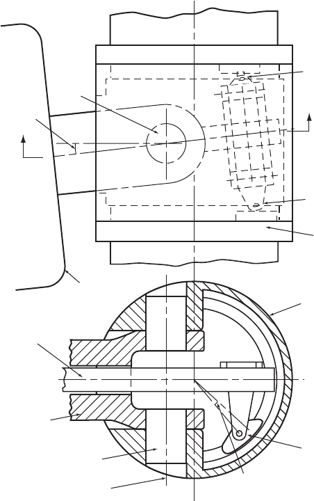
shell (see Figure 6.6), then the max imum teeter excursion is governed by the size of
the aperture.
The teeter response to deterministic and stochastic loads is considered in Section
5.8.8. Although it is evident that a permitted teeter angle range of the order of 58
will accommodate the vast majority of teeter excursions during normal operation, it
is usually impracticable to accommodate the largest that can occur. Hence, in order
to minimize the occu rrence of metal-to-metal impacts on the teeter end stops,
buffers incorporating spring and/or damping elemen ts normally have to be fitted.
These also perform an important role in limiting the much larger teeter excursions
that would otherwise arise during start-up and shut-down, when the centrifugal
restoring moment is reduced.
6.6.3 Pitch–teeter coupling
As described in Section 5.8.8, the magnitude of teeter excursions can be reduced by
coupling blade pitch to teeter angle, in order to generate an aerodynamic restoring
moment proportional to the teeter angle. This can be done simply by setting the
teeter hinge at an angle, known as the Delta 3 angle, to the perpendicular to the
rotor axis. Alternatively, on pitch-controlled machines, pitch–teeter coupling can be
introduced by actuating the blade pitch by the fore-aft motion of a rod passing
through a hol low low-speed shaft (see Figure 6.6).
6.6.4 Teeter stability on stall-regulated machines
At first sight, it might be thought that the teeter motion of a stalled rotor would be
unstable because of negative damping resulting from the negative slope of the C
l
–Æ
curve post-stall. However, two-dimensional aerodynamic theory is a poor predictor
of post-stall behaviour, and it has proved possible to design teetered rotors that are
stable in practice, such as the Gamma 60 (Falchetta et al., 1996) and Nordic 1000
TEETERING 349
(Engstrom et al ., 1997). The concept is explored in detail in investigations by
Armstrong and Hancock (1991) and Rawlinson-Smith (1994).
6.7 Power Control
6.7.1 Passive stall control
The simplest form of pow er control is passive stall control, which makes use of the
post-stall reduction in lift coeffi cient and associated increase in drag coefficient to
place a ceiling on output power as wind speed increases, without the need for any
changes in blade geometry. The fixed-blade pitch is chosen so that the turbine
reaches its maximum or rated power at the desired wind speed. Stall-regulated
Teeter
angle ζ
Teeter
bearing
Blade 'A'
Blade 'B'
Connection
to blade 'A'
Connection
to blade 'A'
Connection
to blade 'B'
Blade 'B'
pitch bearing
Hub shell
SectionJ–J
Teeter axis
Teeter bearing
Low-speed
shaft
Pitch actuator
rod
Nacelle
J
J
Blade 'A' pitch
change due to
teeter angle ζ
Figure 6.6 Pitch–Teeter Coupling
350
CONCEPTUAL DESIGN OF HORIZONTAL-AXIS TURBINES
machines suffer from the disadvantage of uncertainties in aerodynam ic behaviour
post-stall which can result in inaccurate prediction of power levels and blade
loadings at rated wind speed and above. These aspects are considered in greater
detail in Section 4.2.2.
6.7.2 Active pitch control
Active pitc h control achieves power limitation above rated wind speed by rotating
all or part of each blade about its axis in the direction which reduces the angle of
attack and hence the lift coefficient – a process known as blade fea thering. The
main benefits of active pitch control are increased energy capture, the aerodynamic
braking facility it provides and the reduced extreme loads on the turbine when
shut-down (see also Sections 4.2.5, 4.2.7 and 8.2.1).
The pitch change system has to act rapidly, i.e., to give pitch change rates of 58=s
or better in order to limit power excursions due to gusts enveloping the whole rotor
to an accep table value. However, it is not normally found practicable to smooth the
cyclic power fluctuations at blade passing frequency due to blades successively
slicing through a localized gust (Section 5.7.5) with the result that the large power
swings of up to about 100 percent can sometimes occur.
The extra energy obtainable with pitch control is not all that large. A pitch-
regulated machine with the same power rating as a stall-regulated mach ine,
utilizing the same blades and rotating at the same speed will operate at a larger
pitch angle below rated wind speed than the stall-regulated machine, in order to
reduce the angle of attack and hence increase the power output at wind speeds
approaching rated. If the 500 kW, 40 m diameter, 30 r.p.m. stall-regulated machine
described in Section 6.5.3 is taken as baseline, a 500 kW, 30 r.p.m. pitch-regulated
machine utilizing the same blades at optimum pitch would produce about 2 percent
more energy. The optimum rotational speed is found to be about 33 r.p.m., which
increases the energy gain to about 4 percent. The power curve of the 500 kW, 40 m
diameter pitch controlled machine rotating at 33 r.p.m. is compared with the power
curve of the corresponding stall-regulated machine utilizi ng the same blades, but
rotating at 30 r.p.m. in Figure 6.4. Note that the knee in the power curve at rated
speed will be more rounded in practice because the pitch control will not keep pace
with the higher frequency components of turbulence.
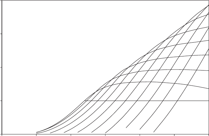
Figure 6.7 shows a family of power curves for a range of positive pitch angles for
the 500 kW, 40 m diameter pitch-controlled machine rotating at 33 r.p.m.. The
intersections of these curves with the 500 kW abscissa define the relationship
between steady wind speed and pitch angle required for power control. It is readily
apparent from the power curve gradients at the intersection points that rapid
changes of wind speed will result in large power swings when the mean wind
speed is high.
The range of blade pitch angles required for power control is typically from 08
(often referred to as ‘fine pitch’), at which the tip chord is in the plane of rotation or
very close to it, and about 358. However, for effective aerodynamic braking, the
blades have to be pitched to 908 or full feather, when the tip chord is parallel to the
rotor shaft with the leading edge into the wind.
POWER CONTROL 351
A variety of pitch actuation systems have been adopted (see also Section 8.5).
They are divided between those in which each blade has its own actuator and those
in which a single actuator pitches all the blades. The former arrangement has the
advantage that it provides two or three independent aerodynamic braking systems
to control overspeed, and the disadvantage that it requires very precise contr ol of
pitch on each blade in order to avoid unacceptable pitch angle differences during
normal operation. An advantage of the latter arrangement is that the pitch actuator,
e.g. a hydraulic cylinder, can be located in the nacelle, producing fore-aft motion of
the pitch linkages in the hub by means of a rod passing dow n the middle of a
hollow low-speed shaft (see Figure 6.8). Alternatively, the axial position of the rod
can be controlled by me ans of a ball-screw and ball-nut arrangement, in which the
ball-nut is driven by a servomotor. Normally the ball-nut is driven at the same
speed as the rotor, but when a change of pitch is required the ball-nut rotational
speed is altered temporarily. This system is arranged to be fail-safe, so that should
the servomotor or its control system fail, the servomotor is braked automatically
and the ball-nut drives the blade pitch to feather .
Where hydraulic cylinders are used to pitch blades individually, they are
mounted within the hub and each piston rod is usually connected directly to an
attachment on the blade bearing (see Figure 6.9). The attachment point follows a
circular pat h as the blade pitches, so the cylinder has to be allowed to pivot. The
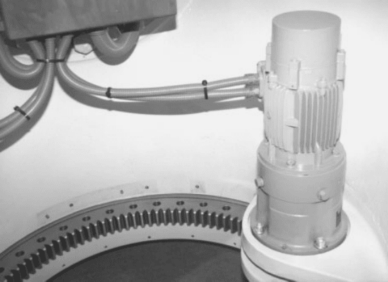
alternative solution of employing an electric motor to drive a pin ion engaging with
teeth on the inside of the blade bearing consequently appears rather neater (see
Figure 6.10). Both systems require a hollow shaft to accommodat e either hydraulic
0
500
1000
1500
2000
0 5 10 15 20 25 30
Wind speed (m/s)
Power output (kW)
22.5⬚
20⬚
17.5⬚
15⬚
12.5⬚
10⬚
7.5⬚
5⬚
2.5⬚
0⬚
500 kW
25⬚
Figure 6.7 Power Curves for Different Pitch Angles: 40 m Diameter Rotor Rotating at 33
r.p.m.
352
CONCEPTUAL DESIGN OF HORIZONTAL-AXIS TURBINES
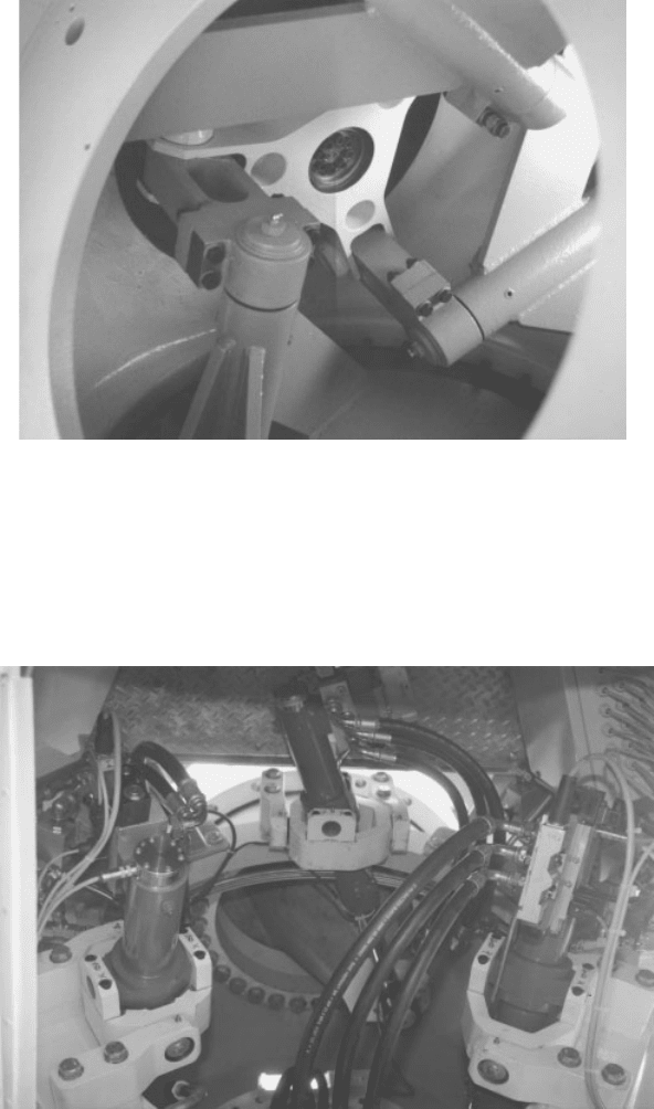
Figure 6.8 Pitch Linkage System Used in Conjuction with a Single Hydraulic Actuator
Located in the Nacelle. (The central triangular ‘spider’ is connected to the actuator by a rod
passing through the hollow low-speed shaft. Links from the spider drive the blade pitch via
braced arms cantilevering into the hub from each blade. Each arm is parallel to its blade axis,
but eccentric to it).
Figure 6.9 Blade Pitching System Using Separate Hydraulic Actuators for Each Blade. (Each
actuator cylinder is supported on gimbal-type mountings bolted to the hub, and its piston
applies a pitching torque to the blade via a cantilevered conical tube eccentric to the blade
axis. The blade is attached to the outer ring of the pitch bearing).
POWER CONTROL 353
hoses or power cables for pitch actuation together with signal cables for pitch angle
sensing. In addition, appropriate slip rings are required at the rear end of the shaft.
Methods of providing back-up power supplies to ensure blade feathering in the
event of grid-loss are considered in Section 8.5.
Although full-span pitch control is the option favoured by the overwhelming
majority of manufacturers, power control can still be fully effective even if only the
outer 15 percent of the blade is pitched. The principal benefits are that the duty of
the pitch actuators is significantly reduced, and that the inboard portion of the
blade remains in stall, significantly reducing the blade load fluctuations. On the
other hand partial-span pitch control has several disadvantages as follows:
• the introduction of extra weight near the tip,
• the difficulty of physically accommodating the actuator within the blade profile,
• the high bending moments to be carried by the tip-blade shaft,
• the need to design the equipment for the high centrifugal loadings found at large
radii,
• the difficulty of access for maintenance.
It should be apparent from the above brief survey of pitch actuation systems that
the design of the hardware required for pitch-regulation is a significant task.
Figure 6.10 Blade Pitching System Using a Separate Electric Motor for Each Blade. (A
pinion, driven by the motor via a planetary gearbox, engages with gear teeth on the inside of
the inner ring of the pitch bearing, to which the blade is bolted. The blade is not attached to
the bearing in this photograph, so the fixing holes are visible).
354
CONCEPTUAL DESIGN OF HORIZONTAL-AXIS TURBINES
