Burton T. (et. al.) Wind energy Handbook
Подождите немного. Документ загружается.

accidental release and the occasional need to deactivate them for maintenance
purposes; the rotor locking device should act on the low-speed shaft, so that its
effectiveness is not dependent on the integrity of the gearbox – typically the
device consists of a pin mounted in a fixed housing, which can be engaged in a
hole in a shaft-mounted disc;
• guards to shield any rotating parts within the nacelle;
• suitable fixtures for the attachment of safety harnesses for personnel working
outside the nacelle.
The designer needs to assess the requirement for all-weather access to the nacelle
at an early stage. Lattice towers afford no protection from the weather when
climbing, so the number of days on which access for maintenance is possible will be
restricted. Similar restrictions will arise if the nacelle cover has to be opened to the
elements in order to provide space for personnel to enter.
Consideration also needs to be given to the means of raising and lowering tools
and spares. If the interior of the tower is interrupted by intermediate platforms,
these operations have to be performed outside, with consequent weather limit-
ations.
Standard rules for electrical safety apply to all electrical equipment. However,
particular care must be taken with the routing of electrical cables between tower
and nacelle, in order to avoid potential damage due to chafing when they twist. If
the power tran sformer is located in the tower bas e or nacelle instead of in a separate
enclosure at ground level, it should be partitioned off to minimize the fire risk to
personnel.
References
Armstrong, J. R. C. and Hancock, M., (1991). ‘Feasibility study of teetered, stall-regulated
rotors’. ETSU Report No. WN 6022.
Bossanyi, E. A. and Gamble, C. R., (1991). ‘Investigation of torque control using a variable
slip induction generator’ ETSU WN-6018, Energy Technology Support Unit, Harwell, UK.
Burton, A. L., Mill, P. W. and Simpson, P. B., (1990). ‘LS1 post-synchronization commission-
ing’. Proceedings of the 12th BWEA Conference, pp 183–193. Mechanical Engineering Pub-
lications, Bury St Edmunds, UK.
Coiante, D. et al., (1989). ‘Gamma 60 1.5 MW wind turbine generator’. Proceedings of the
European Wind Energy Conference, pp 1027–1032.
Corbet, D. C. and Morgan, C. A., (1991). ‘Passive control of horizontal axis wind turbines’.
Proceedings of the 13th BWEA Conference, pp 131–136. Mechanical Engineering Publications,
Bury St Edmunds, UK.
Derrick, A., (1992). ‘Aerodynamic characteristics of novel tip brakes and control devices for
HAWTs’. Proceedings of the 14th BWEA Conference, pp 73–78. Mechanical Engineering
Publications, Bury St Edmunds, UK.
Engstrom, S. et al., (1997). ‘Evaluation of the Nordic 1000 Prototype’. Proceedings of the
European Wind Energy Conference, pp 213–216.
REFERENCES 375
Falchetta, M. et al., (1996). ‘Structural behaviour of the Gamma 60 prototype’. Proceedings of
the European Union Wind Energy Conference, pp 268–271.
Fuglsang, P. and Thomsen, K., (1998). ‘Cost optimization of wind turbines for large-scale
offshore wind farms’. Riso National Laboratory Report No. R-1000. Riso National Laboratory,
Roskilde, Denmark.
Hindmarsh, J., (1984). Electrical machines and their applications. Butterworth Heinemann, UK.
Henderson, G. M., et al., (1990). ‘Synchronous wind power generation by means of a torque-
limiting gearbox’. Proceedings of the 12th BWEA Conference, pp 41–46. Mechanical Engi-
neering Publications, Bury St Edmunds, UK.
Jamieson, P. and Agius, P., (1990). ‘A comparison of aerodynamic devices for control and
overspeed protection of HAWTs’. Proceedings of the 12th BWEA Conference, pp 205–213.
Mechanical Engineering Publications, Bury St Edmunds, UK.
Jamieson, P. and Brown, C. J., (1992). ‘The optimization of stall-regulated rotor design’.
Proceedings of the 14th BWEA Conference, pp 79–84, Mechanical Engineering Publications,
Bury St Edmunds, UK.
Joose, P. A. and Kraan, I., (1997). ‘Development of a tentortube for blade tip mechanisms’.
Proceedings of the European Wind Energy Conference, pp 638–641.
Laithwaite, E. R. and Freris, L. L., (1980). Electric energy: its generation, transmission and use.
McGraw-Hill, Maidenhead, UK.
Law, H., Doubt, H. A. and Cooper, B. J., (1984). ‘Power control systems for the Orkney wind-
turbine generators’. GEC Engineering No 2.
Leithead, W. E. and Rogers, M. C., (1995). ‘Improving damping by a simple modification
to the drive train’. Proceedings of the 17th BWEA Conference, pp 273–278. Mechanical
Engineering Publications, Bury St Edmunds, UK.
McPherson, G., (1990). An introduction to electrical machines and transformers. Second Edition.
John Wiley and Sons, New York, US.
Pedersen, T. K., (1995). ‘Semi-variable speed – a compromise?’. Proceedings of the Wind Energy
Conversion, 17th BWEA Conference, pp 249–260. Mechanical Engineering Publications, Bury
St Edmunds, UK.
Morgan, C., (1994). ‘The prospects for single-bladed horizontal axis wind turbines’. ETSU
Report No. W/45/00232/REP. Energy Technology Support Unint, Harwell, UK.
Petersen, T. P., et al., (1998). ‘Prediction of dynamic loads and induced vibrations in stall’.
Riso National Laboratory Report No. R-1045. Riso National Laboratory, Roskilde, Denmark.
Powles, S. J. R., (1983). ‘The effects of tower shadow on the dynamics of horizontal axis wind
turbines’. Wind Engng, 7, 1, 26–42.
Rawlinson-Smith, R. I., (1994). ‘Investigation of the teeter stability of stalled rotors’. ETSU
Report No. W.43/00256/REP. Energy Technology Support Unit, Harwell, UK.
Saad-Saoud, Z. and Jenkins, N., (1999). ‘Models for predicting flicker induced by large wind
turbines’. IEEE Transactions on Energy Conversion, 14, 3, 743–748.
376
CONCEPTUAL DESIGN OF HORIZONTAL-AXIS TURBINES
7
Component Design
7.1 Blades
7.1.1 Introduction
A successful blade design must satisfy a wide range of objectives , some of which
are in conflict. These objectives can be summarized as follows:
(1) maximize annual energy yield for the specified wind speed distribution;
(2) limit maximum power output (in the case of stall regulated machines);
(3) resist extreme and fatigue loads;
(4) restrict tip deflections to avoid blade/tower collisions (in the case of upwind
machines);
(5) avoid resonan ces;
(6) minimize weight and cost.
The design process can be divided into two stages: the aerodynamic design, in
which objective s (1) and (2) are satisfied, and the structural design. The aerody-
namic design addresses the selection of the optimum geometry of the blade external
surface – normally simply referred to as the blade geometry – which is defined by
the aerofoil family and the chord, twist and thickness distributions. The structural
design consists of blade material selection and the determination of a structural
cross section or spar within the external envelope that meets objectives (4) to (6).
Inevitably there is interaction between the two stages, as the blade thickness needs
to be large enough to accommodate a spar which is structurally efficient.
The focus of Section 7.1 is on blade structural design. After a brief consideration
of the aerodynamic design in Section 7.1.2, practical constraints on the optimum
design are noted in Section 7.1.3 and forms of blade structure surveyed in Section
7.1.4. An overview of the properties of some potential blade materials is given in
Section 7.1.5 and the properties of glass-fibre reinforced plastic (GFRP) and
laminated wood are considered in more detail in Sections 7.1.6 and 7.1.7. Governing
load cases are conside red in Sections 7.1.8 with reference to both stall- and pitch-

regulated machines. Subsequent sections touch upon blade resonance, panel buck-
ling design and blade root fixings.
7.1.2 Aerodynamic design
The aerodynamic design encompasses the selection of aerofoil family and optimiza-
tion of the chord and twist distributions. The variation of thickness to chord ratio
along the blade also has to be considered, but this ratio is usually set at the
minimum value permitted by structural design considerations, as this minimizes
drag losses.
The process for optimizing the blade design of machines operating at a fixed tip
speed ratio is described in Section 3.7.2, where analytical expressions for the blade
geometry parameter,
r
ºC
l
¼
Nc()
2R
ºC
l
and the local inflow angle, , are derived as a function of the local tip speed ratio,
º ¼ ºr=R. (Equations (3.67a) and (3.68a)). If º 1, the expressions can be
approximated by
r
ºC
l
¼
Nc()
2R
ºC
l
¼
8
9º
and ¼
2
3º
(7:1)
If it is decided to maintain the angle of attack, Æ, and hence the lift coefficient, C
l
,
constant along the blade, then these relations translate to
c() ¼
16R
9C
l
Nº
2
1
and ¼
2
3º
Æ (7:2)
so that both the chord and twist are inversely proportional to radius.
In the case of machines operating at constant rotational speed, and hence at
varying tip speed ratio, no parallel analytical solution for the optimum blade
geometry exists. Instead resort must be made to numerical methods based on blade
element – momentum theory, for example using Equations (3.51b) and (3.52a) in
Section 3.8.6.
For pitch-regulated machines, the annual energy capture attributed to the annular
ring swept out by each blade element is determined for the chosen wind speed
distribution, and the variation of energy capture with blade chord and twist at each
‘blade station’ computed. In this way the values of blade chord and twist at
each ‘blade station’ yielding maximum energy capture are identified.
For stall-regulated machines, the method is similar, but the total ann ual energy
capture has to be maximized within the constraint of limiting the maximum total
power output to the machi ne rating. The results of such an investigation are
reported by Fuglsang and Madsen (1995).
378 COMPONENT DESIGN
7.1.3 Practical modifications to optimum design
The result of the optimization desc ribed in the previous section is typically a blade
geometry in which both blade chord and blade twist vary appr oximately inversely
with radius, as illustrated in Figure 3.19. However, because the inboard section of
the blade makes only a small contribution to total power output (Figure 3.30), the
aerofoil section is generally not continued inboard of about 15 percent radius in
practice, and the chor d at this radius is substantially reduced, to perhaps half the
theoretical optimum. It is then often found expedient to taper the chord uniform ly
over the active length of the blade, with the tip chord and chord taper set so that the
chord distribution approximates closely to the optimum over the outboard half of
the blade (Figure 3.20).
The blade root area is normally circul ar in cross section in order to match up with
the pitch bearing in the case of pitchable blades, or to allow pitch angle adjustment at
the bolted flange (to compensate for non-standard air density) in the case of stall-
regulated blades. The transition from the root section to the aerofoil section outboard
of 15 per cent radius should be a smooth one for structural reasons, with the result that
the latter section will have a high thickness to chord ratio of up to about 50 percent.
7.1.4 Form of blade structure
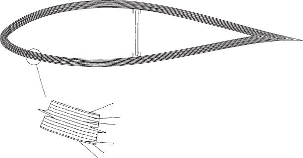
A hollow shell corresponding to the defined blade envelope clearly provides a
simple, efficient structure to resist flexural and torsional loads and some blade
manufacturers adopt this form of construction (see Figure 7.1). However, in the case
of small and medium size machines, where the out-of-plane loads dominate, there
is greater benefit in concentrating skin material in the forward half of the blade,
where the blade thickness is a maximum, so that it acts more efficiently in resisting
out-of-plane bending moments (see Figures 7.2 and 7.3). The weakened areas of the
Glass/Epoxy
25mm Wood veneers
Epoxy glue
Aluminium screen for lightening protection
(unusual)
Glass/Epoxy
Polyurethane point
Figure 7.1 Wood/Epoxy Blade Construction Utilizing Full Blade Shell (Reproduced from
Corbet (1991) by permission of the DT1 Renewable Energy R&D Programme)
BLADES 379
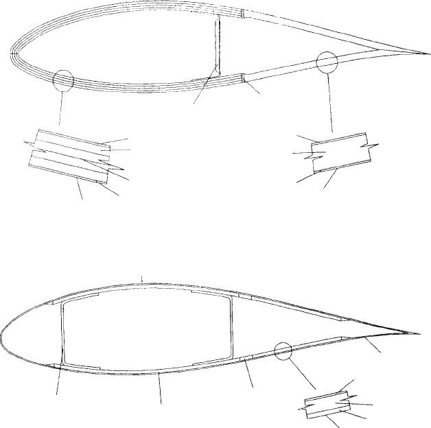
shell towards the trailing edge are then typically stiffened by means of sandwich
construction utilizing a PVC foam filling.
The hollow shell structure defined by the aerofoil section is not very efficient at re-
sisting out-of-plane shear loads, so these are catered for by the inclusion of one or more
shear webs oriented perpendicular to the blade chord. If the load-bea ring structure is
limited to a compact closed hollow section spar, consisting of two shear webs and the
skin sections between them (see Figure 7.4), then a GFRP blade lends itself to semi-
automatic lay-up on a rotating mandrel which can be withdrawn after curing.
7.1.5 Blade materials and properties
The ideal material for blade construction will combine the necessary structural
properties – namely high strength to weight ratio, fatigue life and stiffness – with
low cost and the ability to be formed into the desired aerofoil shape.
Glass/Epoxy web
Glass/Epoxy
4mm Wood veneers
Epoxy glue
Glass/Epoxy
Gel coat
Filler
Glass/Epoxy
Styrofoam
Glass/Epoxy
Gel coat
Figure 7.2 Wood/Epoxy Blade Construction Utilizing Forward Half of Blade Shell (Repro-
duced from Corbet (1991) by permission of the DT1 Renewable Energy R&D Programme)
Moulded GRP shear webs
UD Glass Fibre/polyester
Filler
CSM skins
CSM
PVC foam
CSM
Gel Coat
CSM ⫽ Continuous Strand Mat
Figure 7.3 Glass-fibre Blade Construction Using Blade Skins in Forward Portion of Blade
Cross Section and Linking Shear Webs. (Reproduced from Corbet (1991), by permission of
the DT1 Renewable Energy, R&D Programme)
380
COMPONENT DESIGN
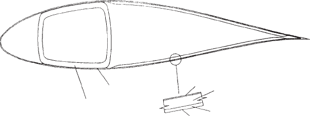
Table 7.1 lists the structural properties of the materials in general use for blade
manufacture and those of some other candidat e materials. For comparative pur-
poses, values are also presented of:
• compressive strength-to-weight ratio,
• fatigue strength as a percentage of compressive strength,
• stiffness-to-weight ratio,
• a panel stability parameter, E/(UCS)
2
.
It is evident that glass- and carbon-fibre composites (GFRP and CFRP) have a
substantially higher compressive strengt h-to-weight ratio compared with the other
materials. However, this apparent advantage is not as decisive as it appears, for
two reasons. First of all, the fibres of some of the plies making up the laminated
blade shell have to be align ed off-axis (typically at 458) to resist shear loads, giving
reduced strengths in the axial direction. Secondly, the rela tively low Young’s
modulus of these composites means that resistance to buckling of the thin skins
governs the design rather than simple compression yielding. The likelihood that
buckling will govern is inversely related to the panel stability parameter, E=(UCS)
2
,
given in the last column of the table, so that materials with high values, such as
wood composites will be least sensitive to buckling. As a result wood composite
blades are generally lighter than equivalent glass-fibre composite blades. Design
against buckling is considered in Section 7.1.10.
It should be noted that the low strength of wood laminate compared with other
materials renders it unsuitable for blades with slender chords operating at high tip
speed, where the flapwise bending moments during operation are inevitably high
in relation to blade thickness. For example, Jamieson and Brown (1992) have shown
that, in the case of a family of stall-regulated machines, the blade stress is highly
sensitive to rotational speed, increasing as the fourth power, if the skin thickness to
chord ratio is maintained constant. Although stresses can be reduced by increasing
the skin thickness, this represents a less and less efficient use of the additional
Adhesive
TFT wound spar
CSM/polyester
PVC foam
Gel coat
CSM/polyester
CSM ⫽ Continuous Strand Mat
Figure 7.4 Glass-fibre Blade Construction Using Compact Spar Wound with Transverse
Filament Tape (TFT) on Mandrel. (Reproduced from Corbet (1991), by permission of the DT1
Renewable Energy R&D Programme)
BLADES 381

Table 7.1 Structural Properties of Materials for Wind-turbine Blades
Material
(NB: UD denotes
unidirectional fibres –
i.e., all fibres running
longitudinally)
Ultimate
tensile
strength
(UTS) (MPa)
Ultimate
compressive
strength (UCS)
(MPa)
Specific
gravity
(s.g.)
Compressive
strength to
weight ratio
UCS/s.g.
Mean fatigue
strength at 10
7
cycles
(amplitude)
(MPa)
Mean fatique
strength as
percentage
of UCS
Young’s
Modulus,
E (GPa)
Stiffness to
weight ratio
E/s.g.
(GPa)
Panel stability
parameter
E/(UCS)
2
(MPa)
1
(Mean for composites,
minimum for metals)
1 Glass/polyester ply with
50% fibre volume
fraction and UD lay-up
860–900
[1] [2]
720 [1] 1.85 390 140 [3] 19% 38 [2] 20.5 0.07
2 Glass/epoxy ply with
50% fibre volume
fraction and UD
lay-up
Properties are generally very close to those for GRP given above
3 Glass/polyester laminate
with 50% fibre volume
fraction and 80% of
fibres running
longitudinally
690–720 580 1.85 310 120 21% 33.5 18 0.1
382 COMPONENT DESIGN

4 Carbon fibre/epoxy ply
with 60% fibre volume
fraction and UD lay-up
1830 [4] 1100 [4] 1.58 700 350 [5] 32% 142 [4] 90 0.12
5 Khaya ivorensis/epoxy
laminate
82 [6] 50 [6] 0.55 90 15 [7] 30% 10 [8] 18 4
6 Birch/epoxy laminate 117 [9] 81 [10] 0.67 121 16.5 [7] 20% 15 [10] 22.5 2.3
7 High Yield Steel (Grade
Fe 510)
510 510 7.85 65 50 [11] 10% 210 27 0.81
8 Weldable aluminium
alloy AA6082 (formerly
H30)
295 [12] 295 [12] 2.71 109 17 [13] 6% 69 [12] 25.5 0.79
Sources:
[1] Mayer (1996) Figure 2.4.
[2] Barbero (1998) Table 1.1.
[3] Mayer (1996) Fig. 14.4.
[4] Carbon fibres exhibit a wide range of properties; figures given here are for one example only, taken from [2].
[5] Based on S– N curve index of m ¼ 14, taken from GL rules.
[6] Bonfield and Ansell (1991) Moisture content ¼ 10%.
[7] Based on S– N curve index of m ¼ 13:4 for scarf-jointed wood laminates, taken from Hancock and Bond (1995).
[8] Bonfield et al. (1992).
[9] Mayer (1996) Table 7.3.
[10] Hancock (Personal Communication). Moisture content ¼ 10%.
[11] Mean value for butt-welded joints with weld profile ground smooth (Class C), taken from BS 5400, Part 10 (1980).
[12] CP 118: 1969 ‘Code of practice for structural aluminium’.
[13] Mean value estimated from mean minus two standard deviations value for ground butt welded joint with shallow thickness transition, Detail Cat 221, in
IIW ‘Fatigue design of welded joints and components’.
BLADES 383
material beyond a skin thickness to chord ratio of 3–4 percent, especially in the
outboard part of the blade, where the blade thickness to chord ratio is low.
Fatigue performance is conveniently measured by mean fatigue strength at 10
7
cycles, as a percentage of ultimate compressive strength. Clearly, carbon-fibre and
khaya/epoxy perform best with a value of about 30 percent. The low value for
welded steel (10 percent), combined with steel’s low strength-to-weight ratio,
renders it uncompetitive for large diameter machines where gravity fatigue loading
becomes important, although it was chosen for some of the early prototype mega-
watt scale machines when the fatigue properties of composite materials were less
well understood.
The stiffness-to-weight ratio determines blade natural frequency. Apart from
CFRP, the values in the table are all in a relatively small range (18–27 GP a),
indicating that material choice will generally only have a marginal effect on
dynamic behaviour.
From the above brief survey, it is apparent that the material with the best all-
round structural properties is carbon-fibre composite. However, it has not found
common use because it is an order of magnitude more costly than other materials.
Instead, the most popular material is glass/polyester, follow ed by glass/epoxy and
wood/epoxy.
Steel is the cheapest material in the raw state, and can be formed into tapering,
curved panels following the aerofoil profile, except in the sharply curved region
near the leading edge. However, it is much harder to introduce a twist into such
panels, and this consideration, together with the poor fatigue properties, means that
steel is rarely used. By contrast, glass- and carbon-fibre composites lend themselves
to wet lay-up in half-moulds profiled to give the correct aerofoil shape, planform
and twist. Laminated wood composite blades are built up in a similar way, but the
veneer thickness has to be restricted to enable the veneers to flex to the required
curvature during lay-up.
In the following paragraphs, the properties of the materials in most common use
for blade manufacture are considered in more detail.
7.1.6 Properties of glass/polyester and glass/epoxy composites
As noted in Table 7.1, the properties of glass/polyester and glass/epoxy plies with
the same fibre volume fraction and lay-up are generally very similar, i.e., the
influence of the matrix is slight. They will therefore be treated as the same material
in the discussion that follows, except in relation to fatigue, where some differences
have been noted. The glass used in blade construction is E-glass, which has good
structural properties in relation to its cost.
The plate elements forming the spar of a GFRP blade are normally laminates
consisting of several plies, with fibres in different orientations to resist the design
loads. Within a ply (typically 0.5–1.0 mm in thickness), the fibres may all be
arranged in the same direction, i.e. UD or unidirectional or they may run in two
directions at right angles in a wide variety of woven or non-woven fabrics.
Although the strength and stiffness properties of the fibre s and matrix are well-
defined, only some of the properties of a ply can be derived from them using simple
384 COMPONENT DESIGN