Burton T. (et. al.) Wind energy Handbook
Подождите немного. Документ загружается.

will be at blade passing frequency and it is an unfortunate coincidence that this
often matches quite closely the natural frequency of oscillation of a small synchro-
nous generator connected to an electrical network.
In practice, synchronous generators are often fitted with add itional cage damper
windings but it is not practical to provide the degree of damping required for wind
turbine applications. Also at higher ratings (above, say, 1 MW) second-or der effects
tend to reduce the damping available from induction generators (Saad-Saoud and
Jenkins, 1999). However, the basic principle remains that the damping provided by
induction generators is necessary for fixed-speed wind turbines.
In contrast, the generators of variable-speed wind turbines are not connected
directly to the netw ork but are de-coupled through solid-state frequency converters.
Hence synchronous generators may be used.
6.10.1 Historical attempts to use synchronous generators
Induction generators are much less useful than synchronous generators for large-
scale power generation.
• The damping action results in higher energy losses in the rotor than with
synchronous generators. It is then, of course, necessary to arrange for the removal
of the heat dissipated in the rotor.
• All the reactive power necessary to energize the magnetic circuits must be
supplied from the network (or by local capacitors). If local capacitors are used
then there is the danger of self-excitation, when connection to the network is lost.
• There is no direct control over the terminal voltage or reactive power flow.
• Induction generators do not produce sustained fault current for three-phase faults
on the network.
• They suffer from problems of voltage instabil ity. This was not an important issue
with limited wind generation but with very large wind farms is becoming of
concern.
Hence, in the early development of wind turbines considerable effort s were made
to use synchronous generators. These involved a number of innovative solutions to
the provision of damping. For example, both Westinghouse in the USA and
Howden in the UK used fluid couplings in the drive train to provide damping. The
Wind Energy Group in the UK mounted a 250 kW synchronous generator using a
spring-damper system and connected a 3 MW synchronous generator through a
sophisticated variable-speed mechanical gearbox (Law, Doubt and Cooper, 1984).
However, these and other similar approaches using synchronous generators on
large prototype wind turbines are now of historical interest only.
TYPE OF GENERATOR 365
6.10.2 Direct-drive generators
There is considerable interest in the application of generators driven directly by the
wind-turbine rotor without a speed increasing gearbox and a number of manufac-
turers offer such wind turbines. However, the power output of any rotating
electrical machine may be generally described by (Laithwaite and Freris, 1980):
P ¼ KD
2
Ln
where D is the rotor diameter, L is the length, n is the rotational speed, and K is a
constant.
Thus it may be seen that if the rotatio nal speed is reduced then it is necessary
either to lengthen the generator in proportion or to increase the diameter. It is
cheaper to increase the diameter as this raises the power by the square rather than
linearly. Thus, direct-drive generators for wind turbines tend to have rather large
diameters but with limited length (Figure 6.20).
Induction generators require a rather small radial distance between the surface of
the rotor and the stator (known as the air-gap). This is necessary to ensure an
adequate air-gap magnetic flux density as all the excitation is provided from the
stator. In contrast, synchronous generators have excitation systems on the rotor and
so can operate with larger air-gaps. It is difficult to manufacture large diameter
electrical machines with small air gaps for mechanical and thermal reasons. Hence
direct-drive wind turbines use synchronous generators (either with permanent
magnet excitation or, more usually, with a wound rotor and electromagnets
providing the field). The use of a synchronous generator, in turn, leads to the
requirement for solid-state frequency conversion equipment to de-couple the gen-
erator from the network and permit variable-speed operation.
6.11 Drive-train Mounting Arrangement Options
6.11.1 Low-speed shaft mounting
The functions of the low-speed shaft are the transmission of drive torque from the
rotor hub to the gearbox, and the transfer of all other rotor loadings to the nacelle
structure. Traditionally the mounting of the low-speed shaft on fore and aft
bearings has allowed these two functions to be catered for separately; the gearbox is
hung on the rear end of the shaft projecting beyond the rear bearing and the drive
torque is resisted by a torque arm. The front bearing is positioned as close as
possible to the shaft/hub flange connection, in order to minimize the gravity
moment due to the cantilevered rotor mass, which usually governs shaft fatigue
design. The spacing between the two bearings will normally be greater than that
between front bearing and rotor hub in order to moderate the bearing loads due to
shaft moment (see Figure 6.15 for an illustration of a typical arrangement).
The opposite approach is to make the gearbox an integral part of the load path
between the low-speed shaft and tower top i.e., an ‘integrated gearbox’. The fore
366 CONCEPTUAL DESIGN OF HORIZONTAL-AXIS TURBINES
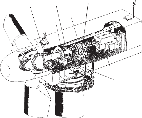
and aft low-speed shaft bearings are absorbed within the gearbox, which moves to
the front of the nacelle in order to minimize the rotor cantilever distance, and the
gearbox casing then transmits the loads to the nacelle bedplate (Figure 6.21). Clearly
this approach requires a much more robust gearbox casing, which must not merely
resist the rotor loads, but do so without deflecting sufficiently to impair its function-
ing. Moreover its fore-aft length has to be increased in order to moderate the
bearing loads due to shaft moment. The benefits lie in the reduced extent of the
bedplate and the elimination of separate bearings requiring separate provision for
lubrication, but a significant disadvantage is that gearbox replacement requires the
removal of the rotor.
A configuration which is becoming increasingly popular is one intermediate
between the two extremes described above, in which only the rear low-speed shaft
bearing is absorbed into the gearbox. The gearbox is usually set well back from the
front bearing in order to reduce the rear bearing loads, and is rigidly fixed to
supporting pedestals positioned on either side of the nacelle. Typical arrangements
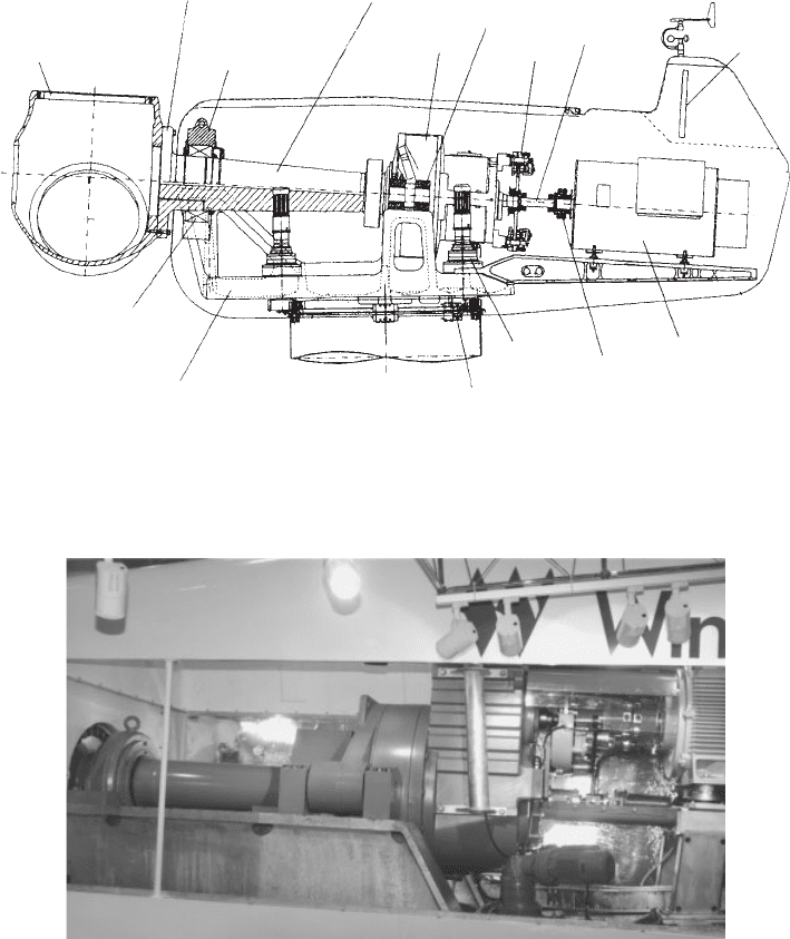
are shown in Figure 6.16, which shows a cross section through the nacelle of the
Nordex N-60 turbine, and in Figure 6.17. Note that the shaft tapers down in
diameter towards the rear reflecting the reducing bending moment. The advantage
of this arrangement is that the gearbox casing is not called upon to carry any
moments due to cantilevered rotor mass or rotor out-of-plane loadings.
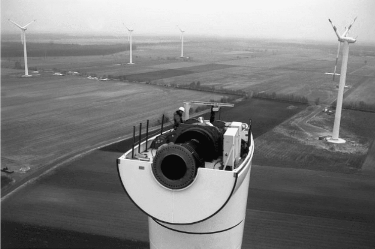
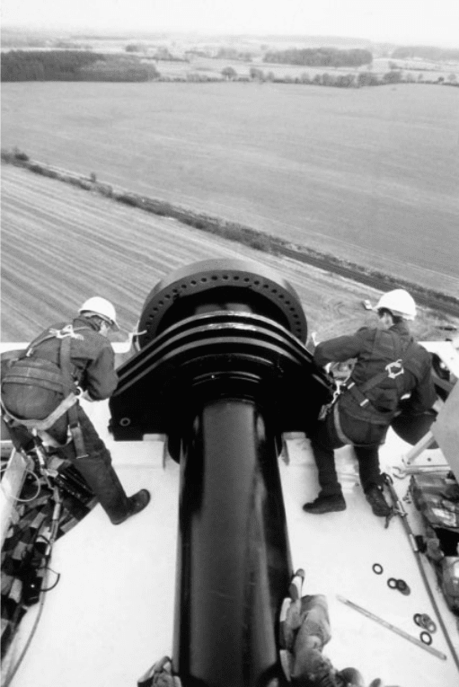
Figures 6.18 and 6.19 are aerial views of the nacelle of a NEG-Micon 1.5 MW
machine with a similar drive train arrangement, after install ation of the low-speed
shaft.
Rotor hub
Front-
bearing
housing
Rear-
bearing
housing
Rotor
brake
Gearbox
Gearbox reaction arm
Generator
Low-speed shaft
Figure 6.15 View of Nacelle Showing Traditional Drive Shaft Arrangement
DRIVE-TRAIN MOUNTING ARRANGEMENT OPTIONS 367
In the case of wind turbines with direct-drive generators, the low-speed shaft
arrangement is dramatically different. The low-speed shaft, which now connects
the rotor hub to the rotor of the generator, is hollow, so that it can be mounted on a
concentric fixed shaft cantilevered out from the nacelle bedplate (see Figure 6.20).
Rotor
hub
Hub mounting flange
Front-bearing
housing
Low-speed shaft
Gearbox
Gearbox mounting
Brake
High-speed
shaft
Cooler
Generator
Safety
coupling
Yaw drive
Yaw brake
Front
bearing
Nacelle
bedplate
Figure 6.16 Nacelle Arrangement for the Nordex N60 Turbine (Reproduced by permission
of Nordex)
Figure 6.17 Drive Train Side View. (From left to right the components visible through the
cut-out in the nacelle wall are: (1) low-speed shaft front bearing, (2) low-speed shaft, (3)
gearbox mountings, (4) gearbox, (5) high-speed shaft with brake, (6) generator. The fabricated
nacelle bedplate is also visible).
368
CONCEPTUAL DESIGN OF HORIZONTAL-AXIS TURBINES
6.11.2 High-speed shaft and generator mounting
The gen erator is normally mounted to the rear of the gearbox on an extension of the
nacelle bedplate and the connecting drive shaft – the ‘high speed shaft’ – is fitted
with flexible couplings at each end, to cater for small misalignments between the
generator and gearbox.
The generator axis is normally offset from the low-speed shaft axis. This is
because, except in the case of machines fitted with a mechanical brake acting on the
rotor, access is required to the rear end of the low-speed shaft for actuation of
aerodynamic braking. Usually the generator is either offset to one side of the
nacelle, which introduces asymmetry into the nacelle bedplate, or it is offset
vertically upwards, which requires a vertical step in the bedplate.
A much more compact arrangement can be obtained by bolting the generator
rigidly onto the rear of the gearbox via an adaptor tu be (see Figure 6.21). The
surfaces of the mating interf aces have to be carefully machined to ensure shaft
alignment, and suitable access has to be provided to the coupling between the
generator and gearbox output shafts. Despite the neatness of this layout, it has only
been adopted by one or two manufacturers.
One consequence of locating the generator in the nacelle is that power cables
running down the tower are required to twist as the nacelle yaws. On some large
machines, the problems associated with the twisting of heavy cables have been
avoided by mounting the generator vertically in the top of the tower, and driving
Figure 6.18 Turbine Assembly in the Air (1). (View of nacelle of 1.5 MW NEG Micon turbine
after installation of low-speed shaft (front) and gearbox. The ring of bolt holes in the low-speed
shaft flange for hub mountings are clearly visible). (Reproduced by permission of NEG Micon)
DRIVE-TRAIN MOUNTING ARRANGEMENT OPTIONS 369
the high-speed shaft via a bevel gear. An alternative solution to the problem of
heavy twisting cables, however, is to leave the generator in the nacelle and to
transform to a higher voltage there as well.
6.12 Drive-train Compliance
The rotational dynamics of the drive train can have a major effect on loading. The
effect is very different in fixed- and variable-speed turbines, but in each case the
consequence of ignoring drive-train dynamics at the design stage can be very
severe.
Figure 6.19 Turbine Assembly in the Air (2). (View of low-speed shaft and front bearing after
installation on 1.5 MW NEG Micon turbine). (Reproduced by permission of NEG Micon)
370
CONCEPTUAL DESIGN OF HORIZONTAL-AXIS TURBINES
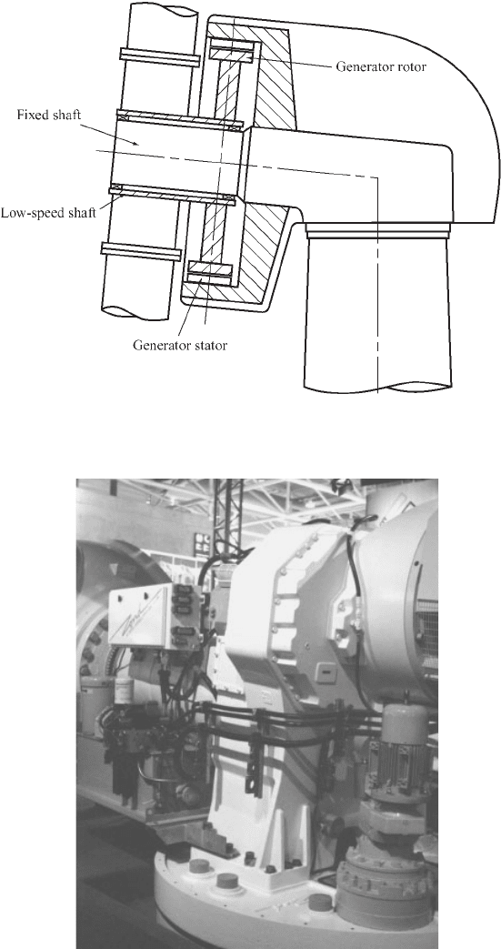
Figure 6.20 Direct-drive Generator Arrangement
Figure 6.21 Integrated Gearbox on the Zond Z-750 turbine. (The gearbox is mounted on a
circular nacelle bedplate, with the hub to the left and generator at the rear. An electrically
driven yaw drive can be seen beneath the generator).
DRIVE-TRAIN COMPLIANCE 371
In the variable-speed case, the dynam ics may be quite simple: the drive train may
be modelled as a rotor and a generator inertia, separated by a torsional spring.
Typically the natural frequency of this resonant system is quite high, of the order of
3–4 Hz. However, this mode is subject to very little damping, especially above
rated where the generator torque is held constant. (Below rated the torque will be
varied as a function of rotational speed, thus providing a small amount of
damping.) There is very little aerodynamic dampi ng from the rotor, and this mode
of vibration can potentially generate very large gearbox torque osc illations. Chapter
8 explains how the control system can be used to damp this mode by appropriate
control of the generator torque, but it is important to ensure that the resonant
frequency does not coincide with a significant forcing frequency such as 6P, which
can make it very difficult to achieve sufficient damping through the control system.
In the fixed-speed case, the directly-coupled induction generator provides a lot of
damping since the air-gap torque increases steeply with generator speed. The
torque–slip curve completely changes the dynamics compared to the variable-
speed case, resulting in a much lower first mode frequency, typically closer to 1 Hz.
The damping factor is strongly dependent on the generator slip: a generator with
0.5% rated slip can give a peak dynamic magnification of perhaps 2 to 5 at the
resonant frequency, whereas with 2 percent slip the peak magnification may be no
more than 1 to 1.5. The position of the peak with respec t to blade-passing frequency
is critical: if the blade-passing frequency is close to the peak, very large gearbox
torque and electrical power oscillations will occur at this frequency. Pitch control
may further exacerbate these.
With a two-bladed turbine the blade-passing frequency tends to be closer to the
resonant peak; with a three-bladed turbine the blade-passing frequency is typic ally
higher, where the dynamic magnification is much lower. Nevertheless, even for
three-bladed turbines it is not uncommon for power and torque oscillations at the
blade passin g frequency to be as large as 50–100 percent during pitch controlled
operation in high winds.
The use of a high-slip generator greatly improves the situation, but there are two
main drawbacks. First, eac h 1 percent of slip corresponds to 1 percent of extra
losses, which significantly reduces the energy yield below rated wind speed.
Second, these extra losses equate with heat dissipation in the generator, making it
more difficult to keep the generator cool, especially in large machines.
An alternat ive to high generator slip which has occasionally been used is a fluid
coupling between the gearbox and the generator. This is also a device which
generates a torque proportional to slip speed, and it suffers from the same draw-
backs as a high-slip generator.
Another technique which has sometimes been used is to reduce the resonant
frequency by introducing additional torsional flexibility into the drive train. This
can be done by means of a quill shaft, a flexible low-speed coupling, or flexible
mounts for the gearbox or even for the whole bedplate. The frequency reduction is,
however, accompanied by a further loss of damping, and it may therefore be
necessary to incorporate additional me chanical damping with the torsional flex-
ibility, which is not always easy to engineer. Torsional flexibility in the high-speed
shaft is not usually practical because of the large angular movement required to
achieve the necessary flexibility: half a revolution may be necessary, compared to
372 CONCEPTUAL DESIGN OF HORIZONTAL-AXIS TURBINES
just one or two degrees at the low-speed shaft. An interesting variant (Leithead and
Rogers, 1995) is to mount the generator on flexible mounts. This system can be
tuned to absorb energy at the blade-passing frequency through an addition al mode
of vibration of the generator casing against its mountings. This mode also affects
the generator slip speed (the difference between rotor and casing speeds) and is
therefore damped by the slip curve. Nevertheless, generator casing displacements
would still need to be of the order of 10–158, which is still not easy to engineer.
6.13 Rotor Position with Respect to Tower
6.13.1 Upwind configuration
The upwind configuration is the one most commonly chosen. The principal
advantage is that the tower shadow effect is much less for the same blade–tower
spacing, reducing both dynamic loads on the blade and rhythmic noise effects. Set
against this is the need to take great care to avoid the risk of blade–tower strikes
with upwind machines, requiring accurate prediction of blade deflections under
turbulent wind loading.
The clearance between the undeflected blade and the tower can be increased by
tilting the low-speed shaft upwards or by increasing the rotor overhang. It is
desirable to keep the rotor overhang small in order to minimize low-speed shaft
and nacelle bedplate bending moments, so the low-speed shaft is normally tilted
upwards by 58 or 68 to provide the necessary blade–tower clearance, at the cost of a
very small reduction in power output.
6.13.2 Downwind configuration
The wind velocity deficit behind a wind-turbine tower is much greater than that in
front of it, to the extent that Powles (1983) has reported a turbulent region with
essentially no forward velocity extending up to four tower diameters downstream
of an octago nal tower. Beyon d this distance, recovery is relatively rapid, with the
deficit reduced to about 25 percent at seven tower diameters downstream.
In addition to the mean wind-speed velocity deficit behind the tower, vortex
shedding results in additional wind-speed fluctuations over and above those
already present due to turbulence. The two effects combine to present a harsh
environment to the blades immediately behind the tower. The blades are subjected
to a large negative impulsive load each time they pass the tower, which contributes
significantly to blade fatigue damage, and the audible tower ‘thump’ that results is
liable to be unwelcome. Designers usually mitigate both effects by positioning the
rotor plane well clear of the tower, but this inevitably increases nacelle costs
somewhat.
An important benefit of the downwind configuration is that it allows the use of
very flexible blades without the risk of tower strike. Such blades benefit by being
ROTOR POSITION WITH RESPECT TO TOWER 373
less severely unloa ded by the tower shadow, because wind loading deflects them
further from the tower in the first place.
6.14 Tower Stiffness
A key consideration in wind turbine design is the avoidance of resonant tower
oscillations excited by rotor thrust fluctuations at rotational or blade-passing
frequency. The damping ratio may be only 2–3 percent for tower fore-aft oscilla-
tions and an order of magn itude less for side-to-side motion, so unacceptably large
stresses and deflections could develop if the blade-passing frequency and tower
natural frequency were to coincide. Rotational frequency is less of a concern,
because cyclic loadings at this frequency only arise if there are geometrical
differences between blades.
Wind-turbine towers are customarily categorized according to the relationship
between the tower natural frequency and the exciting frequencies. Towers with a
natural frequency greater than the blade-passing frequency are said to be stiff,
while those with a natural frequency lying between rotational frequency and blade-
passing frequency are said to be sof t. If the natural frequency is less than rotatio nal
frequency, the tower is described as soft–soft.
If the tower is designed to meet strength requirements and no more, its frequency
category is primarily determined by the ratio of to wer height to turbine diameter,
with the higher ratios producing the softer towers. The principal benefits of stiff
towers are modest – they allow the turbine to run up to speed without passing
through resonance, and tend to radiate less sound. However, since stiff towers
usually require the provision of extra mater ial not otherwise required for strength,
soft towers are generally preferred.
6.15 Personnel Safety and Access Issues
An integral part of wind-turbine design is the inclusion of the necessary safety
provisions for operation and maintenance sta ff. Minimum requirements include the
following:
• ladder access to the nacelle – this needs to be fitted with a fall-arrest device,
unless ladder runs are short and protected by intermediate landings; careful
attention needs to be paid to the route between the tower top and nacelle to avoid
hazards arising from sudden yawing movements;
• an alternative means of egress from the nacelle, for use in case of fire in the tower
– this can take the form of an inertia-reel device , enabling personnel to lower
themselves through a hatch in the nacelle floor;
• locking devices for immobilizing the rotor and the yawing mechanism – rotor
brakes and yaw brakes are not considered sufficient, because of the risk of
374 CONCEPTUAL DESIGN OF HORIZONTAL-AXIS TURBINES
