Burton T. (et. al.) Wind energy Handbook
Подождите немного. Документ загружается.


obtained for machine cost as a function of the ratio of the rated wind speed to that
of the baseline machine, U
R
U
RB
:
C
T
¼ C
TB
(0:125 þ 0:575f0:1 þ 0:9(U
R
=U
RB
)gþ0:142f0:1 þ 0:9(U
R
=U
RB
)
2
g
þ 0:158f0:1 þ 0:9(U
R
=U
RB
)
3
g)
¼ C
TB
(0:2125 þ 0:5175(U
R
=U
RB
) þ 0:1278(U
R
=U
RB
)
2
þ 0:1422(U
R
=U
RB
)
3
)(6:5)
A measure of the cost of energy is obtained by dividing the machine cost from
Equation (6.1) by the annual energy yield, which is calculated for each rated wind
speed by combining the corresponding power curve with the Weibull distribution
of wind speeds. This exercise has been carried out for the 60 m diameter, 1.5 MW
pitch-regulated baseline machine, assuming an annual mean wind speed of 7 m/s,
and taking the rated wind speed of the baseline machine as 14.15 m/s. It is found
that the optimum rated wind speed is 12.4 m/s or 1.77 times the ann ual mean,
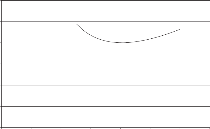
giving an optimum power rating of 1010 kW. The variation in cost of energy with
rated power on either side of the optimum is very small, as can be seen from Figure
6.2, with a departure of 200 kW from the optimum producing an energy cost
increase of only about 1 percent. If is assumed to take the lower value of 0.8, the
optimum rated wind speed rises to 12.7 m/s, giving an optimum power rating of
1135 kW.
It was noted above that if the tower design is governed by extreme winds when
the turbine is shut-dow n, then its cost is a fixed element in the total. The machine
cost formula above then becomes:
C
T
¼ C
TB
(0:37 þ 0:36(U
R
=U
RB
) þ 0:1278(U
R
=U
RB
)
2
þ 0:1422(U
R
=U
RB
)
3
)(6:6)
Table 6.2 Percentage Contribution of Different Components to Machine Cost from Table
6.1, Classified According to the Power Law Assumed to Define the Relationship Between the
Component Mass and the Machine Rated Wind Speed
Components for which
the weight/cost is
independent of rated
wind speed
Components for which
the weight varies as
rated wind speed
Components for which
the weight varies as
rated wind speed
squared
Components for which
the weight varies as
rated wind speed cubed
Component Cost Component Cost Component Cost Component Cost
Foundation 4.2% Blades 18.3% Gearbox 12.5% Generator 7.5%
Controller 4.2% Hub 2.5% Brake system 1.7% Grid
connection
8.3%
Assembly 2.1% Main shaft 4.2%
Transport 2.0% Nacelle 10.8%
Yaw system 4.2%
Tower 17.5%
Total 12.5% Total 57.5% Total 14.2% Total 15.8%
MACHINE RATING 335
which results in an increase in optimum rated power from 1012 kW to 1170 kW for an
annual mean wind speed of 7 m/s for the pitch-regulated machine considered above.
6.3.2 Relationship between optimum rated wind speed and annual
mean
The optimum power rating is of course heavily dependant on the annual mean
wind speed, U
ave
. The optimum rated wind speed, U
Ro
for the above 60 m diameter
pitch-regulated machine is given for a range of annual mean wind speeds in Table
6.3, from which it is apparent that the ratio U
Ro
=U
ave
is approximately constant.
A similar exercise can be carried out to determine the optimum rated power of a
stall-regulated machine, and would yield similar results. However, because stall-
regulated machines reach rated power at a substantially higher wind speed than
pitch-regulated machines of the same rating (see Figure 6.4), the U
Ro
=U
ave
ratio for
stall-regulated mach ines is typically over 2.
6.3.3 Specific power of production machines
It is instructive to investigate the relationship between rated power and swept area
for production machines, and these quantities are plotted against each other in
Figure 6.3 for 75 machines in production in 1996. Although different machines will
80
85
90
95
100
105
110
0 250 500 750 1000 1250 1500 1750
Rated power (kW)
Cost index
Figure 6.2 Variation in Cost of Energy with Rated Power for 60 m Diameter, Pitch-regulated
Machine and Annual Wind Speed of 7 m/s, Based on Cost Model Defined by Equation (6.5)
336
CONCEPTUAL DESIGN OF HORIZONTAL-AXIS TURBINES
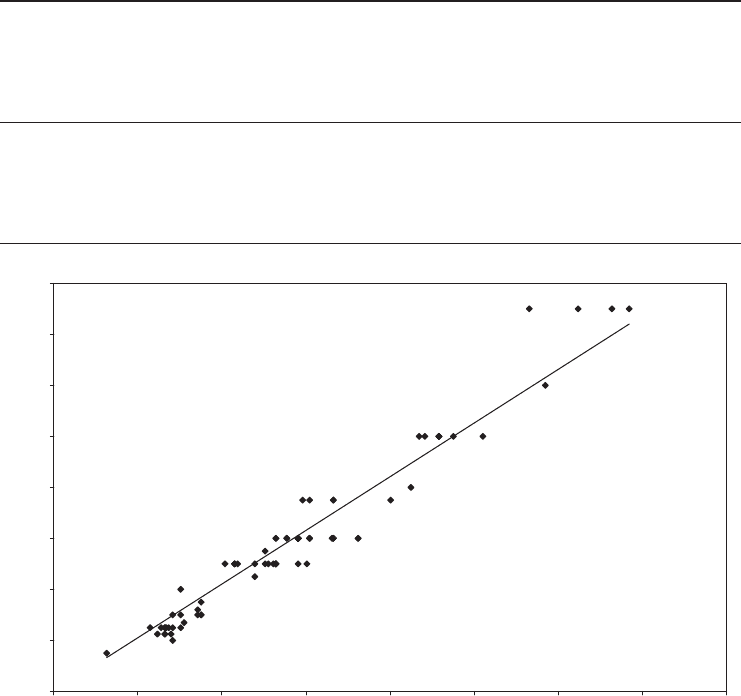
have been designed for different annual mean wind speeds, the degree of scatter is
not large, and a clear trend is apparent, with the line of best fit being close to a
straight line passing through the origin. The mean specific power, defined as rated
power divided by swep t area, is 405 W/m
2
for the 75 machines – close to the
optimum value in Table 6.3 for an annual wind speed of 7.5 m/s.
6.4 Rotational Speed
The aim of the wind turbine designer is the production of energy at mi nimum cost,
subject to constraints imposed by environmental impact considerations. However,
Table 6.3 Variation of Optimum Rated Wind Speed with Annual Mean for Pitch-regulated
Machines
Annual mean
wind speed,
U
ave
(m=s)
Optimum
rated wind
speed,
U
Ro
(m=s)
Ratio
U
Ro
=U
ave
Optimum
rated power
(kW)
Specific power,
defined as rated
power per unit
swept area
(kW=m
2
)
Cost index, with
cost of energy
for a.m.w.s. of
7:5m=s taken
as100
7 12.4 1.77 1012 358 114
7.5 13.1 1.74 1187 420 100
8 13.7 1.72 1376 487 89
8.5 14.4 1.69 1579 558 80
9 15.0 1.67 1797 635 72
0
200
400
600
800
1000
1200
1400
1600
0 500 1000 1500 2000 2500 3000 3500 4000
Swept area (m
2
)
Rated power (kW)
Mean value of
power/swept area ratio
= 405 W/m
2
Figure 6.3 Rated Power versus Swept Area for Turbines in Production in 1997
ROTATIONAL SPEED 337

blade designs optimized for a number of different rotational speeds but the same
rated power produce substantially the same energy yield, so the choice of rotational
speed is based on machine cost rather than energy yield.
One of the key cost drivers is the rotor torque at rated power, as this is the main
determinant of the drive train cost. For a given tip radius and machine rating, the
rotor torque is inversely proportional to rotational speed, which argues for the
adoption of a high rotational speed. However increasing the rotational speed has
adverse effects on the rotor design, which are explored in the following sections.
6.4.1 Ideal relationship between rotational speed and solidity
Equation (3.67a) in Section 3.7.2 gives the chord distribution of a blade optimized to
give maximum power at a particu lar tip speed ratio in terms of the lift coefficient,
ignoring drag and tip loss:
r
ºC
l
¼
8=9
ffiffiffiffiffiffiffiffiffiffiffiffiffiffiffiffiffiffiffiffiffiffiffiffiffiffiffiffiffiffiffiffiffiffiffiffiffiffiffiffiffiffiffiffiffiffiffiffiffiffiffiffiffiffiffiffiffi
(1
1
3
)
2
þ º
2
2
1 þ
2
9º
2
2
2
s
(3:67a)
where º is the tip speed ratio,
r
is the solidity and ¼ r=R. Over the outboard half
of the blade, which produces the bulk of the power, the local speed ratio, º, will
normally be large enough to enable the denominator to be approximated as º,
giving:
r
ºC
l
¼
Nc()
2R
ºC
l
¼
8
9º
(6:7)
where N is the number of blades. After rearrangement, this gives
c()
ÙR
U
1
2
¼
16R
9C
l
N
1
(6:8)
Hence it can be seen that, for a family of designs optimized for differen t rotational
speeds at the same wind speed, the blade chord at a particular radi us is inversely
proportional to the square of the rotational speed, assumi ng that N and R are fixed
and the lift coefficient is maintained at a constant value by altering the local blade
pitch to maintain a constant angle of attack.
Note that Equation (6.8) does not apply if energy yield is optimized over the full
range of operating wind speeds for a pitch-regulated machine. In this case, it has
been demonstrated that the blade chord at a particular radius is approximately
inversely proportional to rotational speed rather than to the square of it (Jamieson
and Brown, 1992).
338 CONCEPTUAL DESIGN OF HORIZONTAL-AXIS TURBINES
6.4.2 Influence of rotational speed on blade weight
The effect of rotational speed on blade weight can be explored with reference to
the family of blade designs just described. As in Section 6.3.1, it is assumed that the
blade design is governed by out-of-plane bending moments in fatigue and that the
moment fluctuations are proportional to the product of the wind spee d fluctuation,
the rotational speed and the chord scaling factor (see Equation (5.25) in Section
5.7.5). By Equation (6.8) the chord scaling factor is inversely proportional to the
square of the rotational speed, so the moment fluctuations simply vary inversely as
the rotational speed.
The thickness to chord ratios at each radius are assumed to be unaffected by the
chord scaling, so the blade section modulus for out-of-plane bending at a given
radius is proportional to the product of the blade shell skin thickness, w(r), and the
square of the local chord. Thus
Z(r) / w(r)(c(r))
2
/ w(r)=Ù
4
(6:9)
In order to maintain the fatigue stress ranges at the same level, we require the blade
section modulus, Z(r), to vary as the moment fluctuations, which, as shown above,
vary inversely as rotational speed. Thus
Z(r) / 1= Ù so w(r)=Ù
4
/ 1=Ù and w(r) / Ù
3
(6:10)
Blade weight is proportional to the skin thickness times chord, and thus varies as
rotational speed.
6.4.3 Optimum rotational speed
On the basis of the assumptions of Section 6.4.2 (which will by no means always
apply), blade weight increases in proportion to rotational speed. However, the
blade out-of-plane fatigue loads, which may govern the design of the nacelle
structure and tower, vary inversely as the rotational speed. It is therefo re likely that,
as rotational speed is increased, there will be a trade- off between reducing costs of
the drive train, nacelle structure and tower on the one hand and increasing rotor
cost on the other, which will determine the optimum value.
6.4.4 Noise constraint on rotational speed
The aerodynamic noise generated by a wind turbine is approximately proportional
to the fifth power of the tip speed. It is therefore highly desirable to restrict turbine
rotational speed, especially when the wind speed – and therefore ambient noise
levels – are low. Consequently manufacturers of turbines to be deployed at normal
sites on land generally limit the tip speed to about 65 m/s. Experience suggests that
this results in wind turbine noise levels on a par with ambient levels at a distance of
400 m, which is the normal minimum spacing between turbines and habitations.
ROTATIONAL SPEED 339
6.4.5 Visual considerations
There is a conse nsus that turbines are more disturbing to look at the faster they
rotate.
6.5 Number of Blades
6.5.1 Ov erview
European windmills traditionally had four sails, perhaps because pre-industrial
techniques for attaching the sail stocks to the shaft lent themselves to a cruciform
arrangement in which the stocks for opposite sails formed a continuous wooden
beam. By contrast the vast majority of horizontal axis wind turbines manufactured
today have either two or three-blades, although at least one manufacturer used to
specialize in one-bladed machines. As the latter are relatively unusual, considera-
tion of them will be restricted to Section 6.5.7, and the rest of Section 6.5 will
concentrate on two- and three-bladed machines.
In comparing the relative merits of machines with differing numbers of blades,
the following fact ors need to be considered:
• performance,
• loads,
• cost of rotor,
• impact on drive train cost,
• noise emission,
• visual appearance.
Some of these factors are strongly influenced by rotational speed and rotor solidity,
and the ideal relationship between these parameters and the number of blades is
considered in the next section. Section 6.5.3 investigates alternative two-bladed
derivatives of a realistic three-bladed baseline design and compares their relative
energy yields and notional costs. Section 6.5.4 reviews the differences in loading
imposed by two- and three-bladed rotors on the supporting structure, and Section
6.5.5 considers the constraint on rotational speed imposed by noise emission. Visual
appearance is considered briefly in Section 6.5.6.
6.5.2 Ideal relationship between number of blades, rotational speed
and solidity
The effect of the number of blades on the blade chord and rotational speed of a
machine optimized for a particular wind speed is given by Equation (6.8):
340 CONCEPTUAL DESIGN OF HORIZONTAL-AXIS TURBINES

Nc()
ÙR
U
1
2
¼
16R
9C
l
1
Hence it can be seen that, if the number of blades is reduced from three to two,
increasing the chord by 50 percent or the rotational speed by 22.5 percent are two of
the options for preserving optimized operation at the selected wind speed. (It is
assumed that the lift coefficient is maintained at a constant value by altering the
local blade pitch to maintain a constant angle of attack.)
6.5.3 Some performance and cost comparisons
Clear-cut comparisons bet ween two- and three-bladed machines are notoriously
difficult because of the impossibility of establishing equivalent designs. Concep-
tually, the simplest option is to increase the chord by 50 percent at all radii and
leave everything else – including rotational speed – unchanged. In the absence of
tip loss, the induction factors, and hence the annual energy yield, remain the same,
but when tip loss is included, the annual energy yield drops by about 3 percent.
However, retention of the same rotor solidity largely negates one of the main
benefits of reducing the number of blades, namely reduction in rotor cost, and so
this option will not be pursued further. Inst ead it is proposed to take a realistic
blade design for a three-bladed machine and look at the performance and cost
implications of using the same blade on a two-bladed machine rotating at different
speeds.
Performance comparisons are affected both by the power rating in relation to
swept area (Section 6.3) and by the aerofoil data used. In this case a 40 m diameter
stall-regulated three-bladed turbine with TR blades (see Example 5.1 in Sectio n
5.6.3) operating at 30 r.p.m. is adopted as the baseline machine, and a power rating
of 500 kW. is chosen, so that the specific power (398 W/m
2
) is close to the norm.
Empirical three-dimensional aerofoil data for a LM 19.0 blade is used (see Figure
5.9), with maximum lift coefficient increasing from blade tip to blade root, as this
results in more accurate power curve predictions. The data are taken from Petersen
et al. (1998). The blade twist distribution is set to give maximum energy yield at a
site where the annual mean wind speed is 7 m/s, while limiting the maximum
power to 500 kW. The design is thus somewhat different from the ideal design
considered in the preceding section, which was optimized for a particular wind
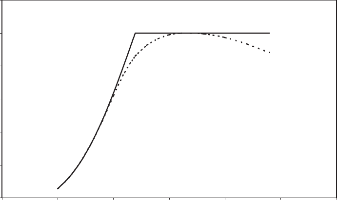
speed (see Figure 6.4 for the predicted power curve).
Two options for a corresponding 40 m diameter stall-regulated two-bladed de-
sign at a site with the same annual mean wind speed are examined and the notional
energy costs compared with that for the baseline three-bladed machine. The costs of
the two- bladed design options in relation to the baseline three-bladed machine are
considered with reference to changes in the cost of the components, using the cost
shares given in Table 6.1 and the methodology of Section 6.3.1.
As before, the blade weight is assumed to increase linearly with rotational speed,
but the cost element for the blades at the baseline rotational speed is reduced by
one third. The weights of the hub, shaft, nacelle and yaw system are also assumed
NUMBER OF BLADES 341
to increase with rotational speed, but no account is taken of the increased loads on
these components for a fixed-hub, two-bladed machine. Tower design is assumed
to be governed by fatigue in the first instance, so tower weight is taken as
proportional to rotational speed. The cyclic thrust loads on the rotor due to
turbulence are virtually the same for two- and three-bladed mach ines rotating at
the same speeds if the blade planforms are the same, so the tower cost element at
the baseline rotational speed is left unchanged.
The weights of the gearbox and brake are taken to be proportional to the rated
torque, P
R
=Ù, while those of the generator and of the cables and equipment forming
the grid connection are taken as proportional to rated power, P
R
. The foundation
cost element is reduced by a quarter for the two-bladed machine in recognition of
the reduced extrem e tower base overturning moment.
The various components are classified into different categories according to the
way in which their weights vary with rotational speed and rated power in Table 6.4.
Also tabulated are the two-bladed machine compo nent costs as a percentage of the
total for the baseline three-bladed machine, tog ether with the sum for each category.
Adopting Equation (6.1) with ¼ 0:9 once more for the relationship between the
cost of a component and its mass, the following expression is obtained for machine
cost as a function of rotational speed and rated power:
C
T
¼ C
TB
(0:114 þ 0:514f0:1 þ 0:9(Ù=Ù
B
)gþ0:142f0:1 þ 0:9(P
R
=P
RB
)(Ù
B
=Ù)g
þ 0:158f0:1 þ 0:9(P
R
=P
RB
)g)(6:11)
¼ C
TB
0:1954 þ 0:4626(Ù =Ù
B
) þ 0:1278(P
R
=P
RB
)(Ù
B
=Ù
RB
) þ 0:1422(P
R
=P
RB
))ð
0
100
200
300
400
500
600
0 5 10 15 20 25 30
Wind speed (m/s)
Power (kW)
Pitch-regulated machine with
TR blades rotating at 33 r.p.m.
(Blade pitch below rated
increased 1.4 degrees compared
with stall-regulated machine)
Stall-regulated machine with TR
blades rotating at 30 r.p.m.
Rotor diameter = 40 m
Figure 6.4 Comparison of Power Curves for 500 kW Stall-regulated and Pitch-regulated
Machines with the Same Planform and Twist Distribution
342
CONCEPTUAL DESIGN OF HORIZONTAL-AXIS TURBINES

Here, P
RB
and Ù
B
are the baseline values of rated power and rotational speed,
500 kW and 30 r.p.m. respectively. The two design options can now be examined.
(a) Planform and rotational speed unchanged from baseline
The maximum output power drops by almost exactly one third due to the
reduction in the number of blades, but the reduction in energy yield is less
severe at 19 percent. This is because, although the coefficient of performance
(C
P
) for the two-bladed machine is very nearly two thirds that of the three-
bladed machine at the low tip speed ratio (62:8=16 ¼ 3:9) corresp onding to
peak power output, the maximum value of C
P
is almost as large as that of the
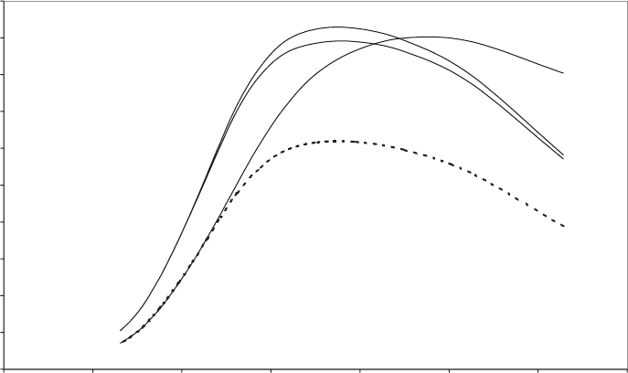
three-bladed machine (see Figure 6.5, which compares the C
P
º curves).
The reduced number of blades and reduced rated power lead to an overall
cost reduction of 16 per cent (made up of 6 percent on the blades, 1 percent on
the foundation and 9 percent on the gearbox, brake, generator and grid
connection), leading to an increase in energy cost of 4 percent compared with
the baseline three-bladed machine.
(b) Chord distribution and diameter unchanged, but rotational speed increased by 18
percent and blade pitch adjusted to give 500 kW power rating
In this two-bladed design variant, the rotational speed and blade pitch are
chosen to maximize energy yield while restricting the rated power to that of
the baseline design. The resultant annual energy yield is 4 percent less than for
the three-bladed machine.
The option of increasing rotational speed is an attractive one as far as the
drive train is concerned because, for a given machine rating, it results in a
reduction in drive train torque and hence in gearbox cost. In this case, the
Table 6.4 Contribution of Different Components to the Cost of a Two-bladed Machine
(Expressed as Percentages of Three-bladed Baseline Machine Cost) and Classified According
to the Relationship Assumed Between the Component Mass and Rotational Speed/rated
Torque/Rated Power
Components for which
the weight/cost is
independent of rated
power or rotational
speed
Components for which
the weight varies as
rotational speed, Ù
Components for which
the weight varies as
rated torque, P
R
=Ù
Components for which
the weight varies as
rated power, P
R
Component Cost Component Cost Component Cost Component Cost
Foundation 3.1% Blades 12.2% Gearbox 12.5% Generator 7.5%
Controller 4.2% Hub 2.5% Brake system 1.7% Grid
connection
8.3%
Assembly 2.1% Main shaft 4.2%
Transport 2.0% Nacelle 10.8%
Yaw system 4.2%
Tower 17.5%
Total 11.4% Total 51.4% Total 14.2% Total 15.8%
NUMBER OF BLADES 343
reduction in gearbox cost due to an 18 percent increase in rotational speed
would yield a 2 percent reduction in total mach ine cost.
As the blade skin thickness is assumed to increase in proportion to rotational
speed, the saving associated with eliminating one blade will be offset by an 18
percent increase in the weight of the remaining two, resulting in a 21 percent
reduction in rotor cost, and a 4 percent reduction in overall cost. The cost
savings on the blades, drive train and foundations are offset by cost increases
on the hub, shaft, nacelle, yaw drive and tower due to increased rotational
speed, resultin g in an overall cost saving of only 1 percent. Hence the energy
cost is 3 percent higher than for the baseline machine.
It is apparent that, with the tower design assumed dependent on fatigue loads,
the two-bladed variants (a) and (b) considered above result in a small increase in
the cost of energy relative to the three-bladed machine. However, if the tower
design is governed by extreme loads rather than fatigue loads, the situation is
reversed; see Table 6.5, in which it is a ssumed that the reduction of extreme load
due to the reduced number of blades results in a 20 percent reduction in tower cost.
The results shown in Table 6.5 indicate that two-bladed, rigid-hub machines are
unlikely to yield significant cost benefits vis-a
`
-vis three-bladed machines, even if the
tower design is determined by extreme loading. However, the results should be
treated with caution, because the cost changes are bas ed on a simplistic treatment
of blade loadings, and of their knock-on effects on other components. (Loads on
rigid-hub two-bladed machines are compared with those on three-bladed machines
in more detail in the next section.)
The loadings on the nacelle of a two-bladed machi ne can be reduced significantly
by the introduction of a teeter hinge between the rotor and the low-speed shaft,
0
0.05
0.1
0.15
0.2
0.25
0.3
0.35
0.4
0.45
0.5
0 2 4 6 8 10 12 14
Tip speed ratio (λ)
Coefficient of performance (C
P
)
Two bladed machine with same
blade geometry
Three bladed machine
(baseline)
Two bladed machine with 50%
increased chord
2/3 times C
P
of
three-bladed machine
Figure 6.5 Comparison of C
P
Curves for Two- and Three-bladed Machines
344
CONCEPTUAL DESIGN OF HORIZONTAL-AXIS TURBINES
