Blake A.J.(ed.) Crystal Structure Analysis
Подождите немного. Документ загружается.

192 Analysis of extended inorganic structures
0
20000
40000
60000
80000
100000
120000
140000
30 35 40 45 50 55 60 65 70
2-theta
Intensity
(a)
(c)
(b)
(d)
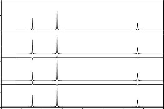
Fig. 14.2 Calculated diffraction patterns for (a) TiO, (b) Ti
0.8
O, (c) TiO
0.8
and (d) Ti
0.8
O
0.8
.
Thelineunderneatheachcalculatedpatternshowsthediscrepanciesobtained when trying
to fit the structure of stoichiometric TiO to the data, refining only an overall scale factor.
Data for Ti
0.8
O
0.8
are indistinguishable from those for TiO.
What if there are vacancies on both the metal and oxygen sites? As
can be seen in Fig. 14.2, for δ = ε the diffraction pattern of a disordered
M
1−δ
O
1−ε
materialisidentical to that of MO. This might seem an ‘exotic’
issue to worry about, but even a material as simple as ‘stoichiometric’
TiO actually contains around
1
/
6 vacancies on both the metal and oxy-
gen sites. For complex disorder problems the use of other techniques
(chemical analysis, density measurements, oxidation-state determina-
tion by other techniques, electron microscopy, solid-state NMR, etc.)
can therefore be vital.
14.2.2 Positional disorder
A second type of disorder frequently encountered is positional disorder
where an atom, or a group of atoms, can occupy one of two or more
sites in a structure. In some cases this is a genuine phenomenon and
can be tackled by introducing partial occupancy on several sites, often
coupled with suitable constraints or restraints. In other cases, however,
apparent disorder could arise due to the wrong choice of space group
or twinning. It should not be forgotten that site and occupational order
may be connected. If one had amaterial with a solid solution of La
3+
(r =
1.30 Å) and Bi
3+
(r = 1.31 Å) on the same site one might not be surprised
if the active lone-pair cation Bi
3+
adopted a slightly different position to
La
3+
. How does one deal with this during refinement? How does one
relate adps for the two cations? Ingenuity and a critical viewpoint are
required!
14.2 Disorder 193
14.2.3 Limits of Bragg diffraction
It should be remembered that Bragg diffraction can only ever tell you
about the average long-range structure of a material and that this can
potentially hide significant features of its structure. Consider the two
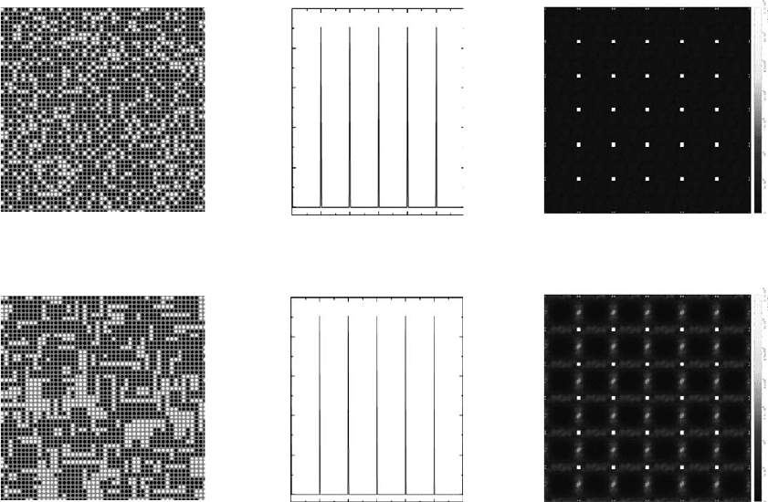
structures in Fig. 14.3. Both represent a simple material in which 30%
of the available sites are vacant. The two structures can be readily dis-
tinguished visually: in one the vacancies are randomly distributed; in
the second they are clustered – if one site is vacant the adjacent site is
more likely to be vacant. Clearly, real-world examples of such mate-
rials could have drastically different properties. Bragg scattering is,
however, completely blind to these differences and the diffracted inten-
sities of hkl reflections of the two materials are identical (Fig. 14.3). The
difference in the structures is revealed only by looking at the diffuse
scattering between Bragg peaks. In a single-crystal experiment this is
seen as streaks between hkl reflections; in a powder experiment it is one
contribution (of several) to the background scattering. The examples in
Fig. 14.3 were kindly supplied by Thomas Proffen. There is an excellent
website that explores these ideas further and allows on-line simulations
0
0
1
2
3
4
Intensity (*10
9
)
12345
[h 2 0]
0
0
1
2
3
4
Intensity (*10
9
)
123 45
[h 2 0]
0
0
1
2
3
4
5
12 34 5
h [r.l.u.]
k [r.l.u.]
0
0
1
2
3
4
5
12 34 5
h [r.l.u.]
k [r.l.u.]
Fig. 14.3 Cross-sections of a 50 × 50 atom structure containing 30% vacancies (drawn as light dots). Bragg scattering (centre plot is of
h, 2, 0 reflections) for a randomly disordered and a clustered model is identical. Differences can be seen only in the pattern of diffuse
intensity (right).
194 Analysis of extended inorganic structures
at www.totalscattering.org/teaching (Proffen et al., 2001; see also Neder
and Proffen, 2008; Egami and Billinge, 2003).
Fig. 14.4 The ideal structure of WO
3
.
14.3 Phase transitions
Phase transitions are a feature of much of the structural chemistry of
extended materials. WO
3
is an apparently simple structure made up of
corner-sharing WO
6
octahedra (Fig. 14.4). As such, one might expect it
to have a simple ∼4 Å cubic unit cell and space group Pm
¯
3m. In reality,
however, its structural chemistry is far more complex. Phase transitions
can occur that involve coupled tiltings of the WO
6
octahedra, and/or in
which W atoms move from the centres of octahedra in different direc-
tions. WO
3
is said to show more phase transitions than any other oxide
and it is only recently that controversy over the true structures of some
of the phases appears to have been resolved.
Part of the difficulty caused by phase transitions (particularly dis-
placive phase transitions) is that they often lead to only subtle changes
in diffraction patterns, with the relative intensities of reflections related
by symmetry in the high-symmetry form showing only slight changes.
Powder diffraction, in which the splitting of, e.g., a cubic 200 reflection
into the 200, 020 and 002 reflections of an orthorhombic system as the
cell metric changes from a = b = c to a ∼ b ∼ c can sometimes be directly
observed, is often a powerful tool – particularly as it avoids the prob-
lems of twinning in single-crystal samples. Phase transitions will often
lead to the formation of superstructures in which the dimensions of one
or more cell edges are doubled or tripled relative to the high-symmetry
structure. If the atoms that move most in the phase transition make only
a small contribution to diffraction (e.g., the movement of oxygen atoms
in a metal oxide), such effects can again be easily missed.
Finally, phase transitions can also lead to incommensurately modu-
lated structures that present further structural complexity. Consider the
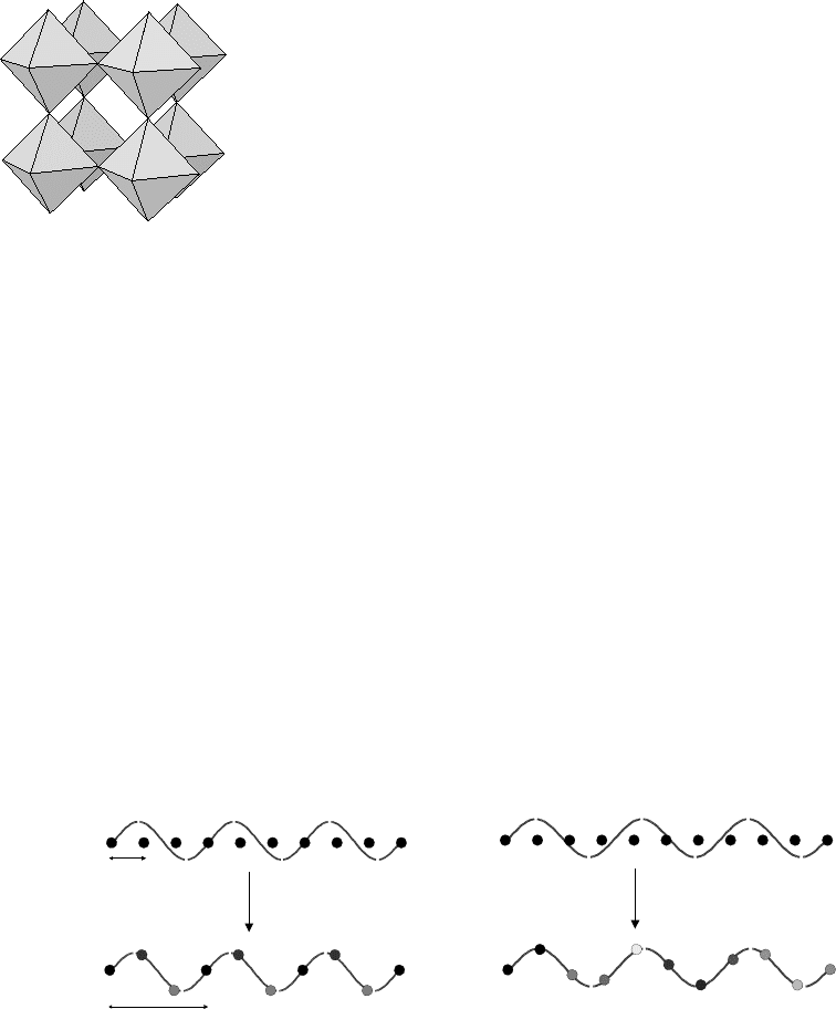
simple structure in Fig. 14.5 that represents a one-dimensional chain of
atoms with a repeat distance a. If a structural change occurs in which
each atom is displaced laterally according to the magnitude of a sine
λ=3a
λ~3a
a
3a
Fig. 14.5 Schematic representation of the formation of (left) a commensurate superstructure with a = 3a
sub
and (right) an
incommensurate superstructure.
14.4 Structure validation 195
wave with λ = 3a, then this can easily be seen to cause a tripling of the
a-axis. In a diffraction pattern one would expect extra reflections to be
observed at points in reciprocal space between the original reflections
(withindicesnh/3, k, l comparedtotheoriginal subcell reflections).What
if the sine wave describing the structural displacements is not exactly
λ = 3a but λ ∼ 3a? The basic structure of the material produced(Fig. 14.5
right) is clearly very similar to that in Fig. 14.5 left. However, the unit
cell of the material is no longer a simple multiple of the original subcell.
One would again expect to see extra superstructure reflections, but they
would no longer appear at simple rational positions between the subcell
reflections. It might be that one can approximate the system by choosing
a very large supercell. For example, in Fig. 14.5 one could approximate
the superstructure using a
sup
= 10a
sub
. However, this is clearly a rather
inelegant approach as one now has a large unit cell requiring a large
number of atoms in the asymmetric unit. There is a more natural lan-
guage to describe such systems – that of ‘incommensurately modulated
structures’ – which can be used to describe either positional or com-
positional fluctuations in materials. This language views the periodic
superstructure merelyas aspecialcase of the moregeneral phenomenon.
More detailed information can be found in a number of places, but is
beyond the scope of this text.
14.4 Structure validation
Assuming that one has successfully solved the structure of an inorganic
material, how can one be sure it is correct? For small-molecule work an
experienced crystallographer will know that a C–C bond length should
be about 1.54 Å, and C=C 1.34 Å; for more exotic distances one can eas-
ily consult the Cambridge Structural Database (Allen, 2002). Distances
significantly different from those expected would immediately cause
concern about the structural model. For inorganic materials such com-
parisons are harder. Co-ordination environments are far less regular,
the range of possible environments is larger, different oxidation states
of elements have different geometric preferences, and there is no direct
equivalent of the CSD to consult.
†
Whilst simple structural considera-
†
There are inorganic databases available
such as the ICSD, PDF-4 and Pauling file,
but they are not as readily interrogated as
the CSD. Inorganic structures can be read
into CSD software to provide searchable
databases but one should always be aware
of bias in the data. How does one take
account of the fact that, e.g., TiO
2
appears
113 times in the database when trying to
decide an average Ti–O distance for a range
of materials?
tions using ionic radii (the sets derived from those initially published
by Shannon and Prewitt in 1969 are the the most widely used; see, for
example, Shannon, 1976) are possible, they are often not desperately
informative.
One relatively straightforward approach is to make use of the bond-
valence concept popularized by Brown and Altermatt (1985), which
builds on ideas originally applied to metals and intermetallics by Paul-
ing in 1947. The basis of the approach is that each bond from atom i to
atom j is assigned a valence v
ij
such that the sum of valences for bonds
from a given atom equals its total valence, V (=v
ij
). The most widely
used expression for the dependence of bond valence on bond length is:
v
ij
= exp[(R
ij
− d
ij
)/b]. (14.1)

196 Analysis of extended inorganic structures
Table 14.1. Bond distances and bond valence sums for BiMg
2
VO
6
(see case history 1).
R
ij
values taken from Brese and O’Keeffe (1991) of Bi 2.094, Mg 1.693 and V 1.803
were used.
O1 O1 O1 O1 O2 O3 O3 O4 Sum
Bi1 d/Å 2.199 2.199 2.236 2.236
v
ij
0.75 0.75 0.68 0.68 2.87
Mg1 d/Å 2.066 2.066 1.980 2.038 2.038
v
ij
0.36 0.36 0.46 0.39 0.39 1.98
Mg2 d/Å 2.066 2.066 2.042 2.042 1.995
v
ij
0.36 0.36 0.39 0.39 0.44 1.95
V1 d/Å 1.688 1.733 1.733 1.684
v
ij
1.36 1.21 1.21 1.38 5.16
Sum (2 × Bi1) 2.16 1.82 1.99 1.82
In this expression d
ij
is the bond length, R
ij
the so-called ‘bond-valence
parameter’ and b a constant usually taken to be 0.37 Å. Whilst the-
oretical justifications of this method have been published, it is usual
to treat the expression as an empirical but effective tool. Brese and
O’Keeffe (1991) have taken this approach and published bond-valence
parameters R
ij
for most common cation–anion combinations using over
1000 carefully chosen crystal structures. These values can be found
on a number of websites including http://www.ccp14.ac.uk/ccp/web-
mirrors/i_d_brown/.
Bond-valence parameters can be used in a number of ways. The most
obvious is to check the validity of a structural model. If a crystal struc-
ture is correct, then one would expect the bond-valence sum for each
element to be close to its formal valency. Values for a typical inorganic
structure (BiMg
2
VO
6
of case history 1) are shown in Table 14.1. Typ-
ically, one would expect valence sums to be within a few per cent of
formal valencies. Values outside this range could suggest an incorrect
model, that one has used valence parameters for the wrong oxidation
state of the element, that the material is highly strained, or that part of
the structure is missing. In this latter context bond-valence sums are par-
ticularly useful for identifying missing H atoms in inorganic structures.
Bond-valence parameters can also be used (via (14.1)) for calculating
expected radii for a given element/anion configuration, or as a criterion
for determining co-ordination numbers (for example, how important is
an oxygen anion at 3.1 Å to the co-ordination environment of a Bi
3+
cation? Answer: it contributes <2% of the valence sum, so not very!).
14.5 Case history 1 – BiMg
2
VO
6
Bismuth magnesium vanadate is a material whose structure was first
reported in orthorhombic space group Cmcm by Huang and Sleight
(1992). Materials of this type have been investigated for catalytic and
14.5 Case history 1 – BiMg
2
VO
6
197
non-linear optical (NLO) properties. With a material of this formula
one might anticipate problems due to pseudo-symmetry (because of
the heavy Bi atom) and significant absorption.
To illustrate both these potential pitfalls data have recently been col-
lected on this material using a Bruker SMART 6000 diffractometer using
Mo-Kα radiation. Afull sphere of data was collected with a frame width
of 0.3
◦
and a counting time of 20 s per frame. Using a default set of
thresholding parameters the same cell and space group were found as in
the published structure (though we actually chose a non-standard space
groupsetting Bbmm rather than Cmcm for analysis). The structure would
solve and refine without any difficulties. Final agreements of R = 2.10%,
wR = 5.64% were obtained for 552 reflections after anisotropic refine-
ment and application of an optimal weighting scheme in the Oxford
CRYSTALS suite of software. Bond distances and angles were all close
to expected values and the co-ordinates were essentially as published.
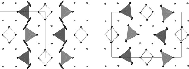
However, it can be seen from Fig. 14.6 that, whilst the adps on most
atoms are what one might expect for a material of this type, one oxygen
atom has an adp that is physically unreasonable and might suggest that
this oxygen site should be split. In fact, careful examination of the raw
frames shows that additional weak reflections are present that violate
the cell centring and show that the true space group of this material
is Pnma. Refinement in this lower-symmetry space group proceeded
smoothly, giving final R-factors for the 1054 observed reflections of
R = 2.13%,wR = 5.27%, with all atoms now showing physically sensi-
ble adps. It can be seen from Fig. 14.6 that the structure is only subtly
different from the Bbmm model. Note that in this case the correct struc-
ture has an R factor that is slightly higher than the incorrect structure
due to the larger number of reflections.
In fact, since the original publication this material has been shown
to undergo a displacive phase transition on warming above ∼300 K
from the primitive to the centred structure (Radosavljevic and Sleight,
2000). In the high-temperature structure the oxygen atoms of the VO
4
Fig. 14.6 Refinements of BiMg
2
VO
6
in Bbmm (left) and Pnma (right); both structures are
viewed down the b-axis with a running to the right. The structure contains VO
4
tetrahedra
(shaded), Bi
2
O
2
chains and 5-coordinate Mg (here shown without bonds for clarity). Adps
have been drawn at the 50% probability level.
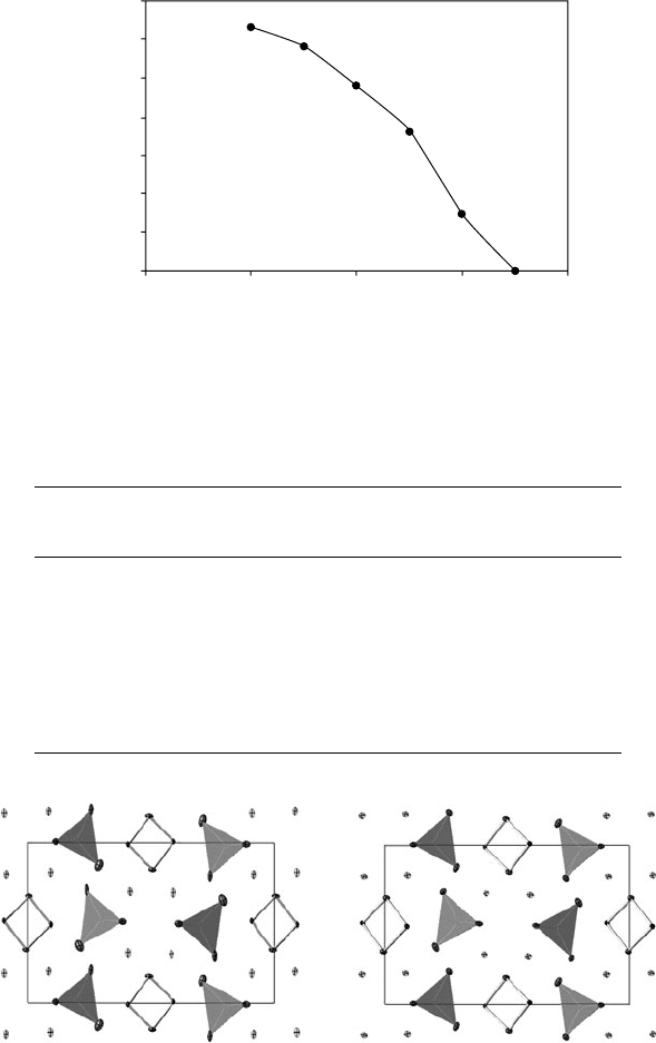
198 Analysis of extended inorganic structures
tetrahedra again show extended adps, which this time are indicative of
dynamic disorder (Fig. 14.7).
The importance of an adequate absorption correction when working
with materials of this type can be seen from Table 14.2 and Fig. 14.8.
0 100
0.14
0.12
0.10
0.08
0.06
0.04
0.02
0.00
P/A Intensity ratio
200 300 400
Temperature (K)
Fig. 14.7 Relative summed intensities of reflections allowed only in Pnma (‘P’ reflections)
and those allowed in both space groups (‘A’ reflections) as a function of temperature.
Table 14.2. R factors for processing and refinement of BiMg
2
VO
6
data.
* failed to converge fully. ** one non-positive-definite adp.
Untreated
Face
indexed SADABS
FI +
SADABS
R
int
(%) 25.8 12.8 5.2 2.9
No. reflections 8983 8983 7680 8955
R/wR (%), isotropic 7.20/17.53 3.80/10.14 5.44/11.85 2.43/6.36
refinement
R/wR (%), anisotropic 6.70/16.16 3.19/8.47 3.82/8.77* 2.21/6.03
refinement
R/wR(%), aniso ref + 6.75/10.85 3.14/7.05 4.05/7.79** 2.13/5.27
optimal weights
Fig. 14.8 Refinements of BiMg
2
VO
6
usingraw(left)andabsorption-corrected data(right);
both structures are viewed down the b-axis with a running to the right. Key as for Fig. 14.6.
14.6 Case history2–Mo
2
P
4
O
15
199
The crystal used for these experiments was an elongated prism of
dimensions 0.02 × 0.03 × 0.27 mm. Without any absorption correction
a merging R factor of 25.8% was obtained. On full anisotropic refine-
ment final agreement factors of R = 6.75, wR = 10.85% were achieved.
The best model could be obtained by application of a combined face-
indexedandSADABS-typeabsorptioncorrection,resultingin a merging
R factor of 2.9% and final agreement factors of 2.13/5.27%. Significant
improvements in the shape of adps were observed (Fig. 14.6).
14.6 Case history2–Mo
2
P
4
O
15
From its formula Mo
2
P
4
O
15
would appear to be a relatively simple
inorganic material and one might therefore expect it to have a simple
structure. In fact, the structure of the material was reported by Costentin
et al. (1992) in space group P2
1
/c with unit cell parameters a = 8.3065,
b = 6.5154, c = 10.7102 Å, β = 106.695
◦
, V = 555.20Å
3
. The cell thus
contains a total of 2 formula units and can be described using 11 atoms in
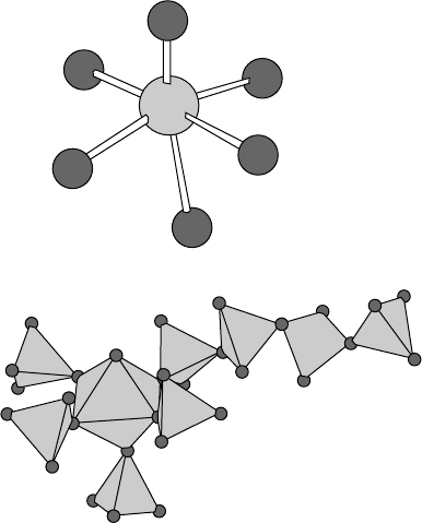
the asymmetric unit. The structure contains MoO
6
octahedra that share
5 of their 6 corners with PO
4
tetrahedra. The PO
4
tetrahedra themselves
share corners to give P
4
O
13
groups (Fig. 14.9). However, despite the
structure being chemically plausible and having an R factor of 3.6%,
there were certain features that were puzzling, including (see Fig. 14.10)
rather large adps on certain atoms.
2.03
2.04
1.65
2.01
2.09
2.15
Fig. 14.9 Local MoO
6
and P
4
O
13
environments in the structure of Mo
2
P
4
O
15
.

200 Analysis of extended inorganic structures
c
a
Fig. 14.10 Left: a polyhedral view of the true superstructure of Mo
2
P
4
O
15
; the incorrect small unit cell is also shown. Middle: adps
(drawn at the 70% probability level) derived from 120 K data using the incorrect subcell model. Right: true atomic positions mapped
back onto the incorrect subcell. Notice the similarity between the incorrect adps and the true static displacements of atoms.
When we re-collected data on this material using a Bruker SMART
6000 it became clear that the true unit cell of this material was consid-
erably more complex than had been initially realized. The actual cell
volume was some 21 times larger than that originally reported, the true
room-temperature cell parameters being a = 24.133(2), b = 19.579(2),
c = 25.109(2) Å, β = 99.962(3)
◦
, V = 11685.13 Å
3
. The unit cell must
then contain some 42 formula units. Automated data processing using
the Bruker XPREP software suggested that the space group was P2
1
/n.
However,carefulmanualinspection of thereflectionlistingrevealedthat
reflections forbidden by the 2
1
axis were in fact present, albeit weak [the
strongest 0k0 reflection observed with k = 2n was 070 with I = 1.54(3);
this ranked 13 352nd of the observed reflections ordered by intensity;
by comparison the strongest reflection observed had I = 9300(120)],
meaning that the true space group was Pn. This in turn implies that the
asymmetric unit of the material must contain 441 independent atoms –
some 430 more than originally thought!
Solving a structure of this complexity that displays severe pseudo-
symmetry is clearly challenging. We took the approach of first solving
the substructure using the unit cell originally published. Using 120 K
data we could refine the substructure to R = 9.5%, though again adps
on certain atoms were rather large. By comparing the indices hkl of
certain reflections based on the (wrong) small unit cell with those of
the correct larger cell we could obtain a transformation matrix to relate
the two structures (see Exercise 3 at the end of this chapter). We could
then transform the subcell co-ordinates to give a starting model for the
high-temperature structure.
Despite now having a chemically plausible starting model, least-
squares refinement is not straightforward. As described in Chapter 13,
if one tries to directly refine a high-symmetry structure in a lower-
symmetry space group the least-squares will invariably diverge. How
then does one move forward? In this case we know a great deal of useful
information about the structure: we know that it contains MoO
6
octahe-
dra that share corners with PO
4
tetrahedra; we know from the literature
that MoO
6
octahedra typically contain 4 Mo–O bonds around 2.05 Å,
14.6 Case history2–Mo
2
P
4
O
15
201
1 short M=O around 1.65 Å and 1 longer M–O around 2.20 Å; we know
that P–O bonds of PO
4
tetrahedra are typically around 1.5 Å; and we
know that P–O bonds in P–O–P linkages are typically slightly longer,
around 1.60 Å. Given this information it is possible to generate a set
of distance restraints to describe the structure and to refine the struc-
tural model, not against a set of diffraction data but directly against the
restraints. The quantity minimized is then the sum of the squared dif-
ferences between prescribed distances and the distances in the model.
Atoms are moved until these differences are minimized. This is called
distance least squares or DLS refinement and has been used to great
effect for many inorganic systems and particularly zeolite frameworks
(see publications by Baerlocher and co-workers). By performing DLS
refinement it is possible to produce plausible structural models, which
can be tested against the data.
In this example it proved relatively straightforward to solve the struc-
ture by simultaneously refining against both the data and the DLS
restraints (252 in total to describe Mo–O distances; 336 to describe P–O
distances; 630/504, respectively, for MoO
6
/PO
4
bond angles; Mo–O
restraints were set up in such a way that each octahedron could have a
range of distances to allow for the expected mixture of short and long
bonds). We used a simulated annealing approach in which we started
refinement from the subcell co-ordinates and then refined the structure
against data and restraints simultaneously to convergence. At conver-
gence, co-ordinates were automatically reset to their initial values ± a
small random displacement and the refinement repeated. This process
was performed on a relatively small 2θ range of data for speed, but
rapidly resulted in a solution with a low R factor. This solution was
then refined against the whole dataset without any restraints to give
R = 3.49% and wR = 5.99% for 43783 reflections with I > 3σ(I).It
is perhaps worth noting that new charge flipping methods can solve
pseudo-symmetry problems such as this far more easily.
The true structure of Mo
2
P
4
O
15
is necessarily complicated! Fig. 14.10
shows the structure in polyhedral representation. The figure also shows
a comparison of the incorrect literature model with the true structure
‘folded back’ into the small unit cell (this can be done by applying the
reverse of the transformation matrix used to generate the initial super-
structure model). Here, each of the atomic positions in the true supercell
becomes one of several closely separated positions in the subcell. It is
instructive to note that the shape of the adps obtained using the incorrect
small cell are closely related to the true static displacements of atoms in
the larger cell.
How can one judge the quality of a structural model for an inor-
ganic crystal structure such as this? Normally one would compare bond
distances and angles with expected values or calculate bond valence
sums for the various atoms in the structure. With a structure this com-
plex (it contains 42 different MoO
6
octahedra and 84 PO
4
tetrahedra),
the structure can be checked for internal self-consistency – it acts as
its own database. Isotropic displacement parameters for all atoms lay
