Bird J. Electrical Circuit Theory and Technology
Подождите немного. Документ загружается.


668 Electrical Circuit Theory and Technology
Since cosωt D sinωt 90
°
,
B
=
V
m
!NA
sin.!t
− 90
°
/ 36.21
Equation (36.21) shows that if the applied voltage is sinusoidal, the
flux density B in the iron core must also be sinusoidal but lagging
by 90
°
.
The condition of low resistance relative to inductive reactance,
giving a sinusoidal flux from a sinusoidal supply voltage, is called
free magnetization.
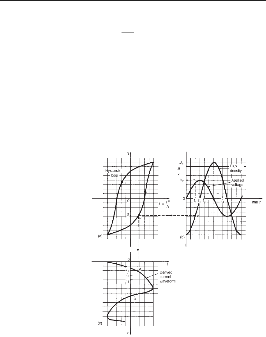
Consider the application of a sinusoidal voltage to a coil wound
on a core with a hysteresis loop as shown in Figure 36.20(a). The
horizontal axis of a hysteresis loop is magnetic field strength H,
but since H D Ni/l and N and l (the length of the flux path) are
constant, the axis may be directly scaled as current i (i.e., i D
Hl/N). Figure 36.20(b) shows sinusoidal voltage
v and flux density
B waveforms, B lagging
v by 90
°
.
Figure 36.20

Complex Waveforms 669
The current waveform is shown in Figure 36.20(c) and is derived
as follows. At time t
1
, point a on the voltage curve corresponds to
point b on the flux density curve and the point c on the hysteresis
loop. The current at time t
1
is given by the distance dc. Plotting
this current on a vertical time-scale gives the derived point e on the
current curve. A similar procedure is adopted for times t
2
, t
3
and
so on over one cycle of the voltage.
(Note that it is important to move around the hysteresis loop
in the correct direction.) It is seen from the current curve that
it is non-sinusoidal and that the positive and negative half-cycles
are identical. This indicates that the waveform contains only odd
harmonics (see Section (36.3)).
(v) If, in a circuit containing a ferromagnetic-cored coil, the resistance
is high compared with the inductive reactance, then the current
flowing from a sinusoidal supply will tend to be sinusoidal. This
means that the flux density B of the core cannot be sinusoidal
since it is related to the current by the hysteresis loop. This means,
in turn, that the induced voltage due to the alternating flux (i.e.,
v D NAdB/dt) will not be sinusoidal. This condition is called
forced magnetization.
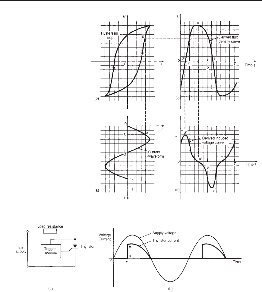
The shape of the induced voltage waveform under forced
magnetizationis obtainedas follows.The current waveformis shown
onaverticalaxisinFigure 36.21(a).Thehysteresisloopcorresponding
to the maximum value of circuit current is drawn as shown in
Figure 36.21(b). The flux density curve which is derived from the
sinusoidal current waveform is shown in Figure 36.21(c). Point a on
the current wave at time t
1
corresponds to point b on the hysteresis
loop and to point c on the flux density curve. By taking other points
throughoutthecurrentcyclethefluxdensitycurveisderivedasshown.
The relationship between the induced voltage
v and the flux
density B is given by
v D NAdB/dt. Here dB/dt represents the
rate of change of flux density with respect to time, i.e., the gradient
of the B/t curve. At point d the gradient of the B/t curve is a
maximum in the positive direction. Thus
v will be maximum posi-
tive as shown by point d’ in Figure 36.21(d). At point e the gradient
(i.e., dB/dt) is zero, thus
v is zero, as shown by point e’. At point f
the gradient is maximum in a negative direction, thus
v is maximum
negative, as shown by point f’. If all such points are taken around
the B/t curve, the curve representing induced voltage, shown in
Figure 36.21(d), is produced. The resulting voltage waveform is
nonsinusoidal. The positive and negative half-cycles are identical
in shape, indicating that the waveform contains a fundamental and
a prominent third harmonic.
(vi) The amount of power delivered to a load can be controlled using a
thyristor, which is a semi-conductor device. Examples of applica-
tions of controlled rectification include lamp and heater controls and
the control of motor speeds. A basic circuit used for single-phase
power control is shown in Figure 36.22(a). The trigger module
contains circuitry to produce the necessary gate current to turn

670 Electrical Circuit Theory and Technology
Figure 36.21
Figure 36.22
the thyristor on. If the pulse is applied at time /ω, where is
the firing or triggering angle, then the current flowing in the load
resistor has a waveform as shown in Figure 36.22(b). The sharp
rise-time (shown as ab in Figure 36.22(b)), however, gives rise to
harmonics.

Complex Waveforms 671
(vii) In microelectronic systems rectangular waveforms are common.
Again, fast rise-times give rise to harmonics, especially at high
frequency. These harmonics can be fed back to the mains if not
filtered.
There are thus a large number of sources of harmonics.
36.9 Further problems
on complex waveforms
Harmonic synthesis
1 A complex current waveform i comprises a fundamental current of
50 A rms and frequency 100 Hz, together with a 24% third harmonic,
both being in phase with each other at zero time. (a) Write down an
expression to represent current, i. (b) Sketch the complex waveform of
current using harmonic synthesis over one cycle of the fundamental.
[(a) i D 70.71sin628.3t C 16.97sin1885tA]
2 A complex voltage waveform
v is comprised of a 212.1 V rms funda-
mental voltage at a frequency of 50 Hz, a 30% second harmonic
component lagging the fundamental voltage at zero time by /2 rad,
and a 10% fourth harmonic component leading the fundamental at zero
time by /3 rad. (a) Write down an expression to represent voltage
v.
(b) Sketch the complex voltage waveform using harmonic synthesis
over one cycle of the fundamental waveform.
[(a)
v D 300sin314.2t C 90sin628.3t /2
C 30sin1256.6t C /3volts]
3 A voltage waveform is represented by
v D 20 C 50sinωt C 20 sin2ωt /2volts
Draw the complex waveform over one cycle of the fundamental by
using harmonic synthesis.
4 Write down an expression representing a current having a fundamental
component of amplitude 16 A and frequency 1 kHz, together with its
third and fifth harmonics being respectively one-fifth and one-tenth
the amplitude of the fundamental, all components being in phase at
zero time. Sketch the complex current waveform for one cycle of the
fundamental using harmonic synthesis.
[i D 16sin210
3
t C 3.2sin610
3
t C 1.6sin10
4
tA]
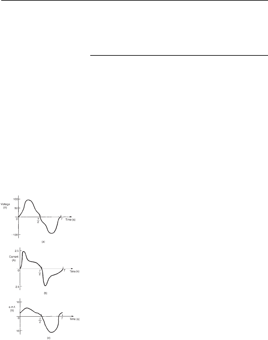
5 For each of the waveforms shown in Figure 36.23, state which
harmonics are likely to be present.
[(a) Fundamental and even harmonics, or all harmonics present,
initially in phase with each other. (b) Fundamental and odd harmonics
only. (c) Fundamental and even harmonics, initially out of phase with
each other (or all harmonics present), some being initially out of phase
with each other.]
Figure 36.23

672 Electrical Circuit Theory and Technology
6 A voltage waveform is described by
v D 200sin 377t C 80sin1131t C /4
C 20sin1885t /3volts
Determine (a) the fundamental and harmonic frequencies of the wave-
form, (b) the percentage third harmonic and (c) the percentage fifth
harmonic. Sketch the voltage waveform using harmonic synthesis over
one cycle of the fundamental.
[(a) 60 Hz, 180 Hz, 300 Hz (b) 40% (c) 10%]
Rms values, mean values and form factor of complex waves
7 Determine the rms value of a complex current wave represented by
i D 3.5sin ωt C 0.8sin
3ωt
3
C 0.2sin
5ωt C
2
A
[2.54 A]
8 Derive an expression for the rms value of a complex voltage wave-
form represented by
v D V
0
C V
1m
sinωt C
1
C V
3m
sin3ωt C
3
volts
Calculate the rms value of a voltage waveform given by
v D 80 C 240 sinωt C 50 sin
2ωt C
4
C 20 sin
4ωt
3
volts
[191.4 V]
9 A complex voltage waveform is given by
v D 150sin 314t C 40sin
942t
2
C 30sin1570t C volts
Determine for the voltage (a) the third harmonic frequency, (b) its
rms value, (c) its mean value and (d) the form factor.
[(a) 150 Hz (b) 111.8 V (c) 91.7 V (d) 1.22]
10 A complex voltage waveform has an rms value of 220 V and it
contains 25% third harmonic and 15% fifth harmonic. (a) Deter-
mine the rms value of the fundamental and each harmonic. (b) Write
down an expression to represent the complex voltage waveform if
the frequency of the fundamental is 60 Hz.
[(a) 211.2 V, 52.8 V, 31.7 V;
[(b)
v D 298.7sin 377t C 74.7sin1131t C 44.8sin1885tV]
11 Define the term ‘form factor’ when applied to a symmetrical complex
waveform. Calculate the form factor of an alternating voltage which
is represented by
v D 50sin314t C 15sin942t C 6 sin 1570tvolts
[1.038]

Complex Waveforms 673
Power associated with complex waves
12 Determine the average power in a 50 # resistor if the current i
flowing through it is represented by
i D 140sinωt C 40 sin3ωt C 20 sin 5ωtmA
[0.54 W]
13 A voltage waveform represented by
v D 100sin ωt C 22 sin
3ωt
6
C 8sin
5ωt
4
volts
is applied to a circuit and the resulting current i is given by
i D 5sin
ωt C
3
C 1.91sin3ωt C 0.76 sin5ωt 0.452amperes
Calculate (a) the total active power supplied to the circuit, and (b) the
overall power factor.
[(a) 146.1 W (b) 0.526]
14 Determine the rms voltage, rms current and average power supplied
to a network if the applied voltage is given by
v D 100 C 50sin
400t
3
C 40 sin
1200t
6
volts
and the resulting current is given by
i D 0.928sin400t C 0.424 C 2.14sin1200t C 0.756amperes
[109.8 V, 1.65 A, 14.60 W]
15 A voltage
v D 40 C 20 sin 300t C 8 sin 900t C 3 sin 1500t volts is
applied to the terminals of a circuit and the resulting current is
given by
i D 4 C 1.715 sin300t 0.540 C 0.389sin900t 1.064
C 0.095sin1500t 1.249A
Determine (a) the rms voltage, (b) the rms current and (c) the average
power.
[(a) 42.85 V (b) 4.189 A (c) 175.5 W]
Harmonics in single-phase circuits
16 A complex voltage waveform represented by
v D 240sin ωt C 60 sin
3ωt
4
C 30sin
5ωt C
3
volts
is applied across (a) a pure 50 # resistance, (b) a pure 4.974
µF
capacitor, and (c) a pure 15.92 mH inductance. Determine for

674 Electrical Circuit Theory and Technology
each case an expression for the current flowing if the fundamental
frequency is 400 Hz.
(a) i D 4.8 sinωt C 1.2 sin
3ωt
4
C 0.6sin
5ωt C
3
A
(b) i D 3 sin
ωt C
2
C 2.25sin
3ωt C
4
C 1.875sin
5ωt C
5
6
A
(c) i D 6sin
ωt
2
C 0.5sin
3ωt
3
4
C 0.15sin
5ωt
6
A
17 A complex current given by
i D 5sin
ωt C
3
C 8 sin
3ωt C
2
3
mA
flows through a pure 2000 pF capacitor. If the frequency of the
fundamental component is 4 kHz, determine (a) the rms value of
current, (b) an expression for the p.d. across the capacitor, and (c)
the rms value of voltage.
[(a) 6.671 mA (b)
v D 99.47sinωt /6
C53.05sin3ωt C /6V (c) 79.71 V]
18 A complex voltage,
v, given by
v D 200sin ωt C 42 sin 3ωt C 25sin5ωt volts
is applied to a circuit comprising a 6 # resistance in series with a
coil of inductance 5 mH. Determine, for a fundamental frequency
of 50 Hz, (a) an expression to represent the instantaneous value of
the current flowing, (b) the rms voltage, (c) the rms current, (d) the
power dissipated, and (e) the overall power factor.
[(a) i D 32.25sin314t 0.256 C 5.50sin942t 0.666
C 2.53 sin1570t 0.918A
(b) 145.6 V (c) 23.20 A (d) 3.23 kW (e) 0.956]
19 An e.m.f. e is given by
e D 40 C 150 sin ωt C 30 sin
2ωt
4
C 10 sin
4ωt
3
volts

Complex Waveforms 675
the fundamental frequency being 50 Hz. The e.m.f. is applied across
a circuit comprising a 100 # resistance in series with a 15
µF capac-
itor. Determine (i) the rms value of voltage, (ii) an expression for
the current flowing and (iii) the rms value of current.
[(i) 115.5 V
(ii) i D 0.639 sinωt C 1.130 C 0.206 sin2ωt C 0.030
C 0.088 sin4ωt 0.559A
(iii) 0.479 A]
20 A circuit comprises a 100 # resistance in series with a 1 mH induc-
tance. The supply voltage is given by
v D 40 C 200sinωt C 50 sin
3ωt C
4
C 15 sin
5ωt C
6
volts
where ω D 10
5
rad/s. Determine for the circuit (a) an expression to
represent the current flowing, (b) the rms value of current and (c)
the power dissipated.
[(a) i D 0.40 C 1.414sinωt /4 C 0.158 sin3ωt 0.464
C 0.029sin5ωt 0.850
(b) 1.08 A (c) 117 W]
21 The e.m.f. applied to a circuit comprising two components connected
in series is given by
D 50 C150sin2 ð 10
3
t C 40sin4 ð 10
3
t
C 20 sin8 ð10
3
tvolts
and the resulting current is given by
i D 1.011sin2 ð 10
3
t C 1.001 C 0.394sin4 ð 10
3
t C 0.663
C 0.233sin8 ð 10
3
t C 0.372A
Determine for the circuit (a) the average power supplied, and (b) the
value of the two circuit components.
[(a) 49.3 W (b) R D 80 #, C D 4
µF]
22 A coil having inductance L and resistance R is supplied with a
complex voltage given by
D 240sinωt C V
3
sin
3ωt C
3
C V
5
sin
5ωt
12
volts
The resulting current is given by
i D 4.064sinωt 0.561 C 0.750 sin3ωt 0.036
C 0.182sin5ωt 1.525A

676 Electrical Circuit Theory and Technology
The fundamental frequency is 500 Hz. Determine (a) the impedance
of the circuit at the fundamental frequency, and hence the values of
R and L, (b) the values of V
3
and V
5
, (c) the rms voltage, (d) the
rms current, (e) the circuit power, and (f) the power factor.
[(a) 59.06 #, R D 50 #, L D 10 mH (b) 80 V,
30 V (c) 180.1 V (d) 2.93 A (e) 427.8 W (f) 0.811]
23 An alternating supply voltage represented by
D 240sin300t 40sin1500t C 60sin2100tvolts
is applied to the terminals of a circuit containing a 40 # resistor,
a 200 mH inductor and a 25
µF capacitor in series. (a) Derive the
expression for the current waveform and (b) calculate the power
dissipated by the circuit.
[(a) i D 2.873sin300t C 1.071 0.145sin1500t 1.425
C 0.149 sin2100t 1.471A
(b) 166 W]
24 A voltage represented by
D 120sin314t C 25sin
942t C
6
volts
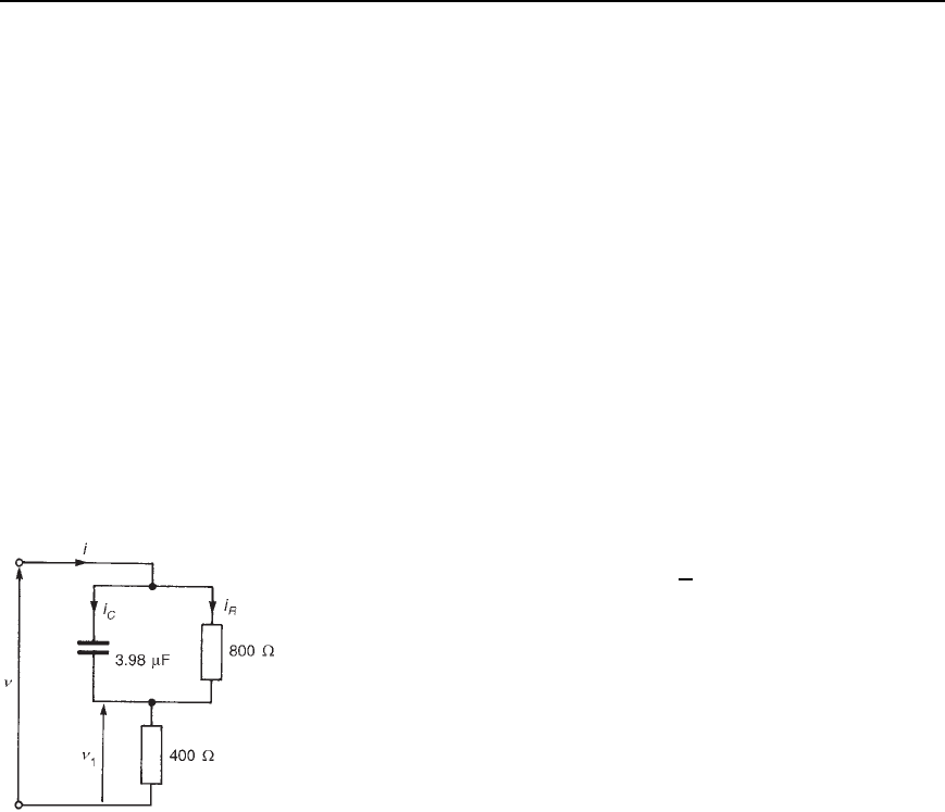
is applied to the circuit shown in Figure 36.24. Determine (a) an
expression for current i, (b) the percentage harmonic content of the
supply current, (c) the total power dissipated, (d) an expression for
the p.d. shown as
1
and (e) expressions for the currents shown as
i
R
and i
C
.
Figure 36.24
[(a) i D 0.134sin314t C 0.464 C 0.047sin942t C 0.988A
(b) 35.07% (c) 7.72 W
(d)
1
D 53.6sin314t C 0.464 C 18.8 sin942t C 0.988V
(e) i
R
D 0.095sin314t 0.321 C 0.015 sin942t 0.261A
i
C
D 0.095sin314t C 1.249 C 0.045 sin942t C 1.310A]
Harmonic resonance
25 A voltage waveform having a fundamental of maximum value 250 V
and a third harmonic of maximum value 20 V is applied to a series
circuit comprising a 5 # resistor, a 400 mH inductance and a 0.5
µF
capacitor. Determine (a) the fundamental frequency for resonance
with the third harmonic and (b) the maximum values of the funda-
mental and third harmonic components of the current.
[(a) 118.6 Hz (b) 0.105 A, 4 A]
26 A complex voltage waveform has a maximum value of 500 V at
the fundamental frequency of 60 Hz and contains a 17th harmonic
having an amplitude of 2% of the fundamental. The voltage is applied

Complex Waveforms 677
to a series circuit containing resistance 2 #, inductance 732 mH
and capacitance 36.26 nF. Determine (a) the maximum value of the
17th harmonic current, (b) the maximum value of the 17th harmonic
p.d. across the capacitor, and (c) the amplitude of the fundamental
current.
[(a) 5 A (b) 23.46 kV (c) 6.29 mA]
27 A complex voltage waveform is given by the expression
D 150sinωt C 25sin
3ωt
6
C 10sin
5ωt C
3
volts
where ω D 314 rad/s. The voltage is applied to a circuit consisting
of a coil of resistance 10 # and inductance 50 mH in series with a
variable capacitor.
(a) Calculate the value of the capacitance which will give resonance
with the triple frequency component of the voltage. (b) Write down
the corresponding equation for the current waveform. (c) Determine
the rms value of current. (d) Find the power dissipated in the circuit.
[(a) 22.54
µF
(b) i D 1.191sin314t C 1.491 C 2.500sin942t 0.524
C 0.195 sin1570t 0.327A
(c) 1.963 A (d) 38.56 W]
28 A complex voltage of fundamental frequency 50 Hz is applied to
a series circuit comprising resistance 20 #, inductance 800
µHand
capacitance 74.94
µF. Resonance occurs at the nth harmonic. Deter-
mine the value of n. [13]
29 A complex voltage given by D 1200sinωt C 300sin3ωt C
100sin5ωt volts is applied to a circuit containing a 25 # resistor,
a12
µF capacitor and a 37 mH inductance connected in series. The
fundamental frequency is 79.62 Hz. Determine (a) the rms value of
the voltage, (b) an expression for the current waveform, (c) the rms
value of current, (d) the amplitude of the third harmonic voltage
across the capacitor, (e) the circuit power, and (f) the overall power
factor.
[(a) 877.5 V
(b) i D 7.991 sinωt C 1.404 C 12sin3ωt
C 1.555sin5ωt 1.171A
(c) 10.25 A (d) 666.4 V (e) 2626 W (f) 0.292]
