Bemelmans J. et. al. (editor) Elliptic and Parabolic Problems: Rolduc and Gaeta 2001
Подождите немного. Документ загружается.

440
Theorem 4.1 We consider a star-shaped domain f2 with C
4
boundary and a shell with
"shallow" middle surface, i.e. a < 1. There
existsT
0
> 0, such that for initial conditions
(y
1
,— y°) G F' one can find a control
(W,W,LJ)
S L
2
(E) X L
2
(S) X L?(Y,), acting on the
whole boundary S such that
w = 9
n
u, w = d
nn
u
3
,
LJ
=
—d
n
<p
on E,
where (u,
<j>)
is the unique solution of the evolution problem (3) associated to the initial
conditions (u°, u
1
) 6 F given by:
A(u°,u
1
) = (y
1
,-y
0
)-
This control drives the system to rest for T > T°.
Proof.
Once the expression of the boundary condition (5) has been estabUshed, the proof
is directly adapted from HUM to the system of equations considered here. •
5 Summary
For each case, we recall the direct and indirect inequalities leading to exact controllability
(with appropriate definitions of the functional c of the energy E° and of the control time
T°).
(1) 3d elasticity ([4]): there is a control on part S° C S of the boundary
C f c(u,u)dS < (T+1)E° , (T-T°)E° <C f c(u,u)dE.
(2) 2d elastic shell ([5]): there is control on part E° of the boundary, for "shallow" shells
C [ c(u, u)vWE < (T + 1)£°, (1 - a)(T - T°)E° <C f c(u,
u)y/a~d?,.
(3) 3d piezoelectricity ([6]): for a star-shaped domain, there is a control on the whole
boundary
C| /" [c(u,u) + 2e(u,0)-d(M)]d£| < (T+1)E°,
f
(T-T°)E° < C [c(u,u) + 4^)]dE.
(4) 2d piezoelectric
shell:
for a star-shaped domain and "shallow" shell, there is a control
on the whole boundary
C| / [c(u,u) + 2e(u,0)-d(0,0)yodE| < (T + l)E°,
f
(l-o-){T-T°)E° < C [c(u,u) + d(^,^)]v^dS.
The next step ([7]) of this study is, for the last three cases, to obtain a control on only
a part of the boundary S and for ordinary (not shallow) shells.
441
References
[1] S. Busse, P.G. Ciarlet and B. Miara, Justification d'un modele lineaire bi-dimensionnel
de coques "faiblement courbees" en coordonnees curvilignes. Math. Model. Num.
Anal., 31(3), (1997), 409-434.
[2] P.G.Ciarlet and B. Miara, Justification of the Two-Dimensional Equations of a Lin-
early Elastic Shallow Shell. Comm. Pure Appl. Math., 45 (1992), 327-336.
[3] Ch. Haenel, Modelisation, analyse et simulation numerique de coques piezoelectriques.
Doctoral Dissertation, University Pierre et Marie Curie (2000).
[4] J.-L. Lions, Controlabilite exacte, perturbations et stabilisation de systemes distribues.
Tome 1. Masson, Paris (1988).
[5] B. Miara and V. Valente, Exact Controllability of a Koiter Shell by a Boundary Action.
J. Elasticity, 52 (1999), 267-287.
[6] B. Miara, Controlabilite d'un corps piezoelectrique. C.R.A.S., Serie I, 333 (2001),
267-270.
[7] B. Miara, Carleman estimates for elastic and piezoelectric shells. Work in progress.
Optimal control approach for the fluid-structure
interaction problems
CM. Murea
Universite de Haute-Alsace,
Laboratoire de Mathematiques et Applications,
4,
rue des Freres Lumiere,
68093 MULHOUSE Cedex, Prance,
Email: c.murea@uha.fr
1 Introduction
A fluid-structure interaction problem is studied. We are interested by the displacement
of the structure and by the velocity and the pressure of the fluid.
The contact surface between fluid and structure is unknown a priori, therefore it is a
free boundary like problem.
In the classical approaches, the fluid and structure equations are coupled via two
boundary conditions: the continuity of the velocity and of the constraint vector at the
contact surface.
In our approach, the equality of the fluid and structure velocities at the contact surface
will be relaxed and treated by the Least Squares Method.
We start with a guess for the contact forces. The displacement of the structure can be
computed. We suppose that the fluid domain is completely determined by the displace-
ment of the structure. Knowing the actual domain of the fluid and the contact forces, we
can compute the velocity and the pressure of the fluid.
In this way, the equality of the fluid and structure forces at the contact surface is
trivially accomplished.
The problem is to find the contact forces such that the equality of the fluid and
structure velocities at the contact surface holds.
It's a exact controllability problem with Dirichlet boundary control and Dirichlet
boundary observation.
In order to obtain some existence results, this exact controllability problem will be
transformed in an optimal control problem using the Least Squares Method.
This mathematical model permits to solve numerically the coupled fluid-structure
problem via partitioned procedures (i.e. in a decoupled way, more precisely the fluid and
the structure equations are solved separately).
The aim of this paper is to present an optimal control approach for a fluid structure
interaction problem and some numerical tests.
442
443
2 Notations
We study the flow in the two-dimensional canal of breadth L
2
Q = {(x
u
x
2
) € R
2
; 0 < xi < L
2
, -H < x
2
< +H} .
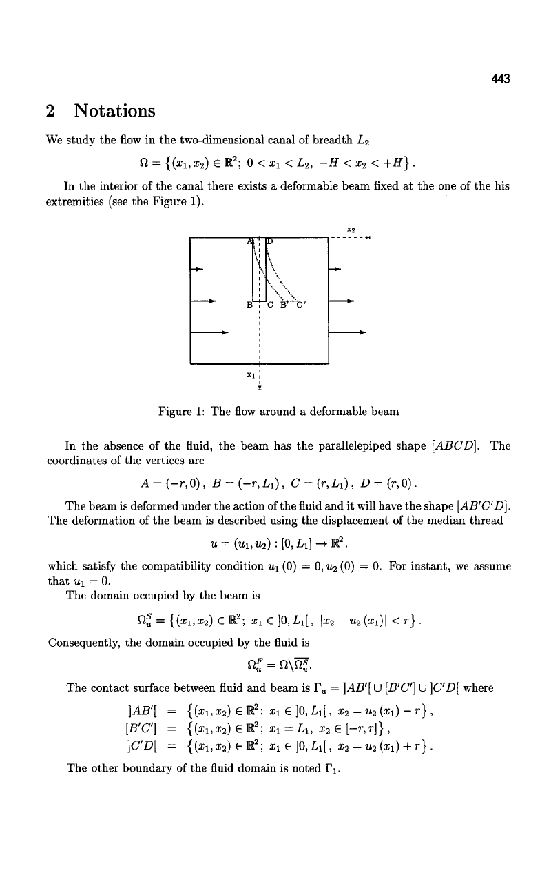
In the interior of the canal there exists a deformable beam fixed at the one of the his
extremities (see the Figure 1).
X2
*
—-
A
B
\
i
K
i
b
i
\
c
if5
r
""c'
1
-
xi!
Figure 1: The flow around a deformable beam
In the absence of the fluid, the beam has the parallelepiped shape [ABCD]. The
coordinates of the vertices are
A = (-r,0), B = (-r,L
1
), C={r,L
x
), D = (r,0).
The beam is deformed under the action of the fluid and it will have the shape [AB'C'D].
The deformation of the beam is described using the displacement of the median thread
w
= (wi,w
2
) : [0,L!]-)-K
2
.
which satisfy the compatibility condition u
x
(0) = 0, u
2
(0) = 0. For instant, we assume
that «i = 0.
The domain occupied by the beam is
nf = {{x
u
x
2
) €M
2
; xx G]0,Li[, \x
2
- u
2
(
Xl
)\ < r} .
Consequently, the domain occupied by the fluid is
n«
=
n\fif.
The contact surface between fluid and beam is F
u
= \AB'[
U
[B'C]
U
]CD[ where
}AB'[ = {(a;i,a;
2
)GR
2
;
Xl
e]0,Li[, x
2
= u
2
(x
x
) - r) ,
[B'C] = {{x
u
x
2
) e R
2
; x
x
= L
u
x
2
e [-r,r]} ,
}C'D[ = {(i
1
,x
2
)6R
2
;iie]0,L
1
[,i
2
=
u
2
(i
1
)+r-}.
The other boundary of the fluid domain is noted IV
444
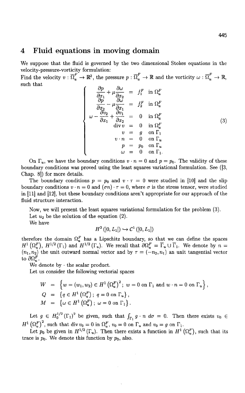
3 Beam equations
The beam has one end clamped and the other is free. It is deformed under the flexion
efforts and we suppose that the longitudinal traction compression forces are negligible. We
don't take into account the effect of the transverse shear. We present the mathematical
model, following [1].
In view of the Sobolev Embedding Theorem, we have
H
2
QQ,L
1
\)^C
1
([0,L
1
])
and we denote
^{^fl
2
(]0,ii[); 0(O) = 0'(O) = O}.
Let D
2
6 K + be given by the formula
D
2
= E I x\ dx
2
dxz
is
where E is the Young's module and S is the cross section of the beam. We set
!
a
s
•
U x U -> R
os(
^
)=i?2
LS
(a;i)
S
(a:i)
^
(1)
Remark 1 As a consequence of the Lax-Milgram Theorem, we have the following result:
Let f^ 6 L
2
(]0,Li[) and
r)
2
£ L
2
(]0,Li[). Then the problem:
Find
U2
in U such that
a
s
{u
2
,ip)= 77
2
(zi)V(zi)cfai+ / fiix^ipix^dxu Vip 6 U (2)
V]0,Li[ *']0,L
l
[
has a unique solution.
The volume forces (the gravity forces) are included in f
2
. We denote by rj
2
the fluid
forces acting on the beam.
When the data and the solution are smooth enough the solution u
2
verifies the strong
formulation given by:
<(xi) = jf M*i) + /
2
S
(zi)) , Vsi € ]0, Li[
U2(0) = u'
2
(0) = «5(Li) = <(L
X
) = 0.
In the particular case f£ = 0 and ^2(^1) = a + fixi +
72:1,
we obtain
^-[15(^-4^+61
+ (x(- 20xiL{ + 45L?) 7] •
445
4 Fluid equations in moving domain
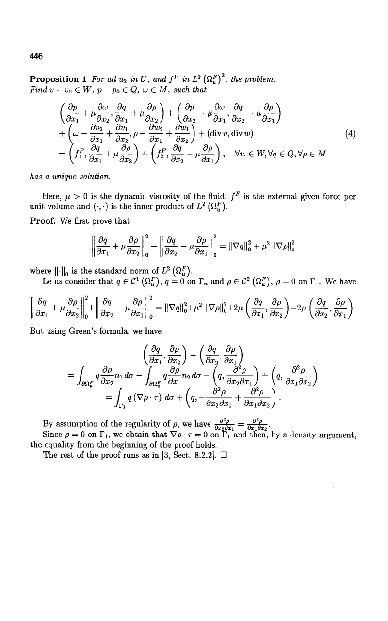
We suppose that the fluid is governed by the two dimensional Stokes equations in the
velocity-pressure-vorticity formulation:
—F n —F —F
Find the velocity v : Q
u
—•
R , the pressure p : U,
u
—>•
R and the vorticity w : fi
u
—>•
R,
such that
dp du
dx\ 8x2
dp dui
dxn dxi
ov
2
dv\
— —
~i-
—•
dxi dx
2
divii
V
v
•
n
P
w
=
=
—
=
=
=
=
=
/i
F
f?
0
0
9
0
Po
0
inO£
infif
in£2£
inQ£
onTi
on r
u
on T„
on IV
On r„, we have the boundary conditions v
•
n = 0 and p =
po-
The validity of these
boundary conditions was proved using the least squares variational formulation. See ([3,
Chap.
8]) for more details.
The boundary conditions p = p
0
an
d v • T = 0 were studied in [10] and the slip
boundary conditions v
•
n = 0 and (an)
•
r = 0, where a is the stress tensor, were studied
in [11] and [12], but these boundary conditions aren't appropriate for our approach of the
fluid structure interaction.
Now, we will present the least squares variational formulation for the problem (3).
Let u
2
be the solution of the equation (2).
We have
fl
a
ao,iiD^c
1
([o,Li])
therefore the domain H£ has a Lipschitz boundary, so that we can define the spaces
H
1
(fi£), H
1
'
2
(I\) and H
1
'
2
(r„). We recall that dQ^ =T
U
U TV We denote by n =
(ni,n
2
) the unit outward normal vector and by r = (—ra
2
,ni) an unit tangential vector
to
dVtl.
We denote by • the scalar product.
Let us consider the following vectorial spaces
W = Iw = (w
u
w
2
) e H
1
(fi£)
2
; w = 0 on Ti and w
•
n = 0 on T
u
\ ,
Q = {qeH
1
(fij) ; q = 0 on T
u
) ,
M = {ueff
1
(^);u =
0onr
1
}.
Let g € HQ (IV)
2
be given, such that f
v
g • n da = 0. Then there exists v
0
e
H
1
(n£) , such that divi>
0
= 0 in H£, v
0
= 0 on V
u
and v
0
= g on IV
Let po be given in H
1
?
2
(T
u
). Then there exists a function in H
1
(fi„), such that its
trace is p
0
. We denote this function by p
0
, also.
446
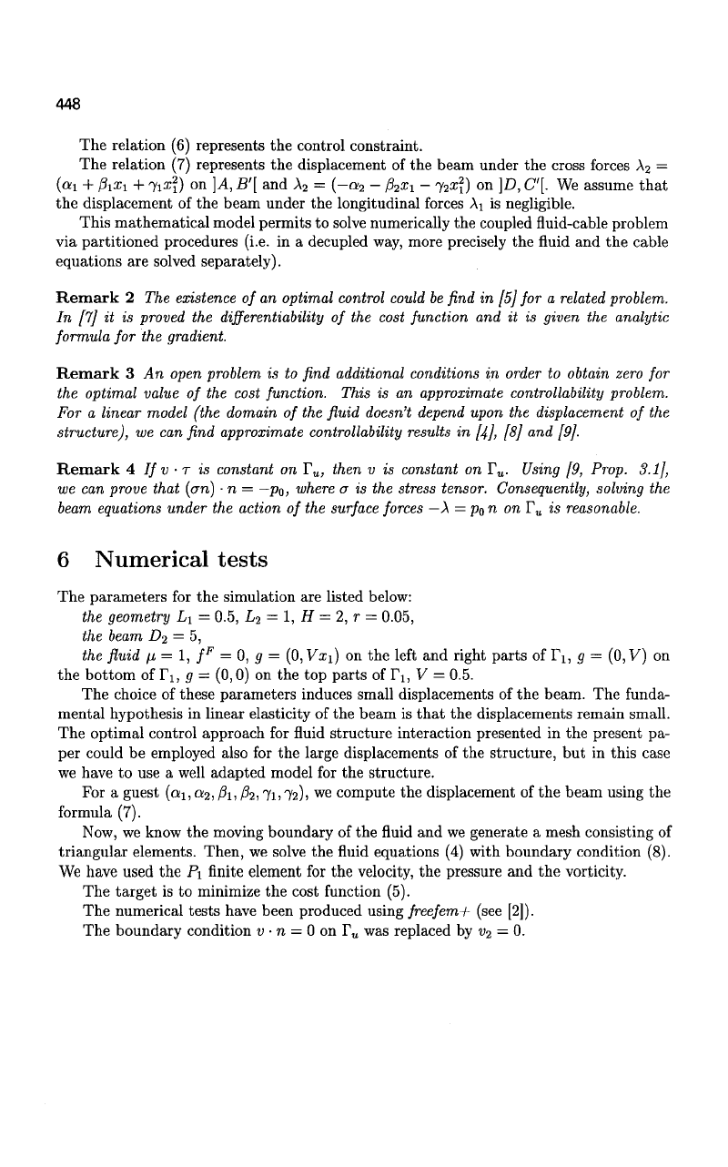
Proposition
1 For all u
2
in U, and f
F
in L
2
(Q„
) , the
problem:
Find
v
—
v
0
G
W, p
—
p
0
6 Q,
u>
€ M,
such that
(
dp did dq 8p\ ( dp dw dq dp \
\dxi dx
2
'dxi
dx
2
) \dx
2
dxi' dx
2
dx\)
(
dv
2
dv
x
dw
2
dwA
+
{
U
-dx-
1
+
dx-2'
p
-dx:
+
8
X
-
2
)
+(dlVV
>
dlYw)
(
4)
-{*>&
+
'&)
+ {*•&--£)> v—,v
9eQ
,v,eM
has
a
unique solution.
Here,
/i > 0 is the
dynamic viscosity
of
the fluid,
f
F
is the
external given force
per
unit volume
and (•,
•)
is the
inner product
of L
2
(£^)-
Proof.
We first prove that
dq_
+
dp_
dx\
8x2
dq
dp
8x2
dxi
l|V^
+
M
2
||Vp||^
where ||-||
0
is the
standard norm
of L
2
(Q
F
).
Le
us
consider that
q € C
1
(^„),
q = 0 on r
u
and
p e C
2
(tt
F
),
p = 0 on
Ti. We have
dq
dp
dxi
ox
2
+
dq_
dx2
dxi
;.^dwiv*«,(^g)-*.(i.i)
But using Green's formula,
we
have
(8q_
8p\ _ /8q_ 8^
\dxi'
8x
2
)
\dx
2
'dxi
f
d
P ; f
d
P j (
d
P \ (
d2
P
•
/
9^— "lda- q-— n
2
da-
[q, I + [q,
Jenz
"
x
2
Jen?
dx
±
\
8x
2
dx
x
J
\
dx^dx-t
=
[
q(V
P
.r)da
+
(q,-^l-
+
J^-\.
I q(Vp-r) da +
(q,-
8x28x1
8x
\dx
2
)
By assumption
of
the regularity
of p, we
have
9x2^1 <Ja:i0:E2'
Since
p = 0 on Ti, we
obtain that Vp
•
T
= 0 on Fi and
then,
by a
density argument,
the equality from
the
beginning
of
the proof holds.
The rest
of
the proof runs
as in
[3, Sect. 8.2.2].
•

447
5 Optimal control approach of the fluid-structure in-
teraction problem
In the classical approaches, the fluid and structure equations are coupled via two boundary
conditions: continuity of the velocities and continuity of the forces on the contact surface.
We denote by A = (Ai,A
2
) the forces induced by the beam on the contact surface.
Consequently,
—A
represent the forces induced by the fluid acting to the beam.
We denote by S : M -4 U the application which computes the displacement of the
beam knowing the forces on the contact surface. This application is linear and continuous.
We denote by F
:
U x M —>WxQ the application which computes the velocity and
the pressure of the fluid knowing the displacement of the beam (therefore the domain of
the fluid) and the forces on the contact surface. This application is non-linear on U x M.
r
s
u
A
F
v, P
Figure 2: The computing scheme
We search to find out A, such that ii|r„ = 0. This is a exact controllability problem.
In our approach, the target condition will be relaxed. We assume that the forces on the
contact surface have the form
A
= —
p
a
n, where p
a
is the pressure of the fluid.
We consider the following optimal control problem:
subject to:
inf J(ai,a
2
,ft,
/
9
2
,7i,72) = ^ II"
•
i"Ho,r„
(ai,a
2
,/0i,j02,7i,72) e K C
'.
(5)
(6)
M^i) = [15 (x\ - 4a:iLi + 6Z»i)
(OJI
- a
2
)
+3 (x\ - lOxii? + 20L?) (A - fa)
+ (x\ - 20iiL? + 45L}) (71 - 72)]
(v,p,
<j)
solution of the Stokes problem (4) with
f (ai + jSiii + 71Z?), if (x
u
x
2
) € ]A, B'\
p
0
(x
u
x
2
) = < (a
2
+ fax\ +
j
2
xl),
if (xi, x
2
) e }D, C]
{ (I-|i)
Po
(B') + (i + ^po(C), if (x
u
x
2
)£}B',C'{
(7)
(8)
It's an optimal control problem with Dirichlet boundary control (p
0
) and Dirichlet
boundary observation (i>|r„)-
448
The relation (6) represents the control constraint.
The relation (7) represents the displacement of the beam under the cross forces \
2
=
(ai + h
x
i + Ti^i) on ]A, B'[ and A
2
= (-»2 - h^\ - 72K?) on ]D, C'[. We assume that
the displacement of the beam under the longitudinal forces Ai is negligible.
This mathematical model permits to solve numerically the coupled fluid-cable problem
via partitioned procedures (i.e. in a decupled way, more precisely the fluid and the cable
equations are solved separately).
Remark 2 The existence of an optimal control could be find in
[5]
for a related problem.
In [7] it is proved the differentiability of the cost function and it is given the analytic
formula for the gradient.
Remark 3 An open problem is to find additional conditions in order to obtain zero for
the optimal value of the cost function. This is an approximate controllability problem.
For a linear model (the domain of the fluid doesn't depend upon the displacement of the
structure),
we can find approximate controllability results in
[4],
[8] and [9].
Remark 4 If v
•
T is constant on T
u
, then v is constant on T
u
. Using [9, Prop. 3.1],
we can prove that (an)
•
n =
—po,
where a is the stress tensor. Consequently, solving the
beam equations under the action of the surface forces —\=p
0
n on T
u
is reasonable.
6 Numerical tests
The parameters for the simulation are listed below:
the geometry L\ = 0.5, L
2
= 1, H = 2, r = 0.05,
the beam D
2
= 5,
the fluid fi = 1, f
F
= 0, g = (0, Vx{) on the left and right parts of T\, g = (0, V) on
the bottom of Ti, g = (0,0) on the top parts of T\, V = 0.5.
The choice of these parameters induces small displacements of the beam. The funda-
mental hypothesis in linear elasticity of the beam is that the displacements remain small.
The optimal control approach for fluid structure interaction presented in the present pa-
per could be employed also for the large displacements of the structure, but in this case
we have to use a well adapted model for the structure.
For a guest (a
1;
a
2
, A, hi
7i> 72)1
we
compute the displacement of the beam using the
formula (7).
Now, we know the moving boundary of the fluid and we generate a mesh consisting of
triangular elements. Then, we solve the fluid equations (4) with boundary condition (8).
We have used the P\ finite element for the velocity, the pressure and the vorticity.
The target is to minimize the cost function (5).
The numerical tests have been produced using freefem+ (see [2]).
The boundary condition v
•
n = 0 on T
u
was replaced by v
2
= 0.
449
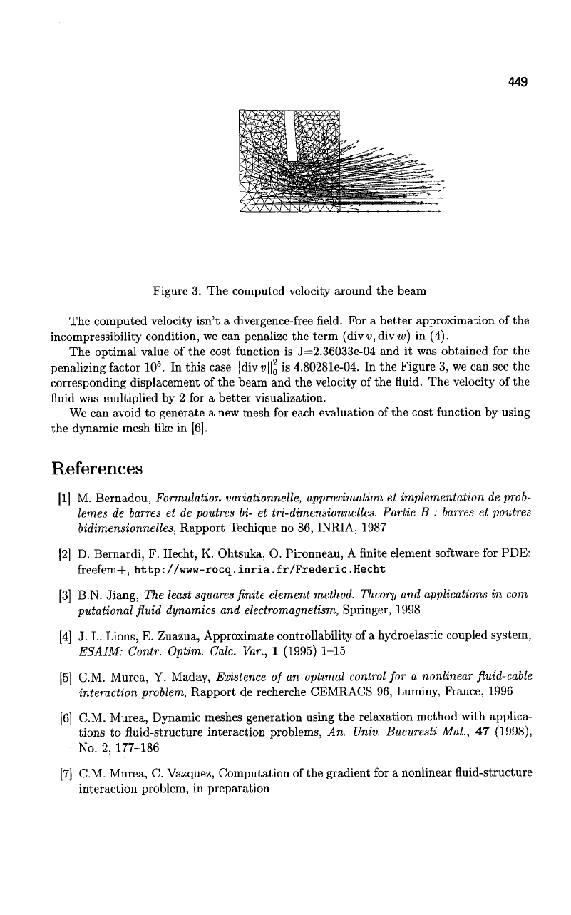
Figure 3: The computed velocity around the beam
The computed velocity isn't a divergence-free field. For a better approximation of the
incompressibility condition, we can penalize the term (di\v,divw) in (4).
The optimal value of the cost function is J=2.36033e-04 and it was obtained for the
penalizing factor 10
5
. In this case ||divu||g is 4.80281e-04. In the Figure 3, we can see the
corresponding displacement of the beam and the velocity of the fluid. The velocity of the
fluid was multiplied by 2 for a better visualization.
We can avoid to generate a new mesh for each evaluation of the cost function by using
the dynamic mesh like in [6].
References
[1] M. Bernadou, Formulation variationnelle, approximation et implementation de prob-
lemes de barres et de poutres bi- et tri-dimensionnelles. Partie B : barres et poutres
bidimensionnelles, Rapport Techique no 86, INRIA, 1987
[2] D. Bernardi, F. Hecht, K. Ohtsuka, O. Pironneau, A finite element software for PDE:
freefem+, http: //www-rocq. inria. fr/Frederic. Hecht
[3] B.N. Jiang, The least
squares
finite element
method.
Theory and applications in com-
putational fluid dynamics and electromagnetism, Springer, 1998
[4] J. L. Lions, E. Zuazua, Approximate controllability of a hydroelastic coupled system,
ESAIM:
Contr. Optim. Calc. Var., 1 (1995) 1-15
[5] CM. Murea, Y. Maday, Existence of an optimal control for a nonlinear fluid-cable
interaction problem, Rapport de recherche CEMRACS 96, Luminy, France, 1996
[6] CM. Murea, Dynamic meshes generation using the relaxation method with applica-
tions to fluid-structure interaction problems, An. Univ. Bucuresti Mat., 47 (1998),
No.
2, 177-186
[7] CM. Murea, C. Vazquez, Computation of the gradient for a nonlinear fluid-structure
interaction problem, in preparation
