Beer F.P., Johnston E.R., DeWolf J.T., Mazurek D.F. Mechanics of Materials
Подождите немного. Документ загружается.

Apago PDF Enhancer
277
Problems
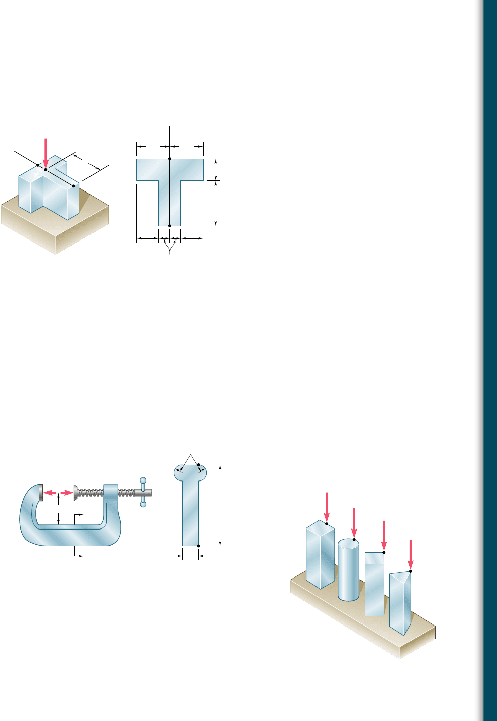
4.117 A vertical force P of magnitude 20 kips is applied at point C located
on the axis of symmetry of the cross section of a short column.
Knowing that y 5 5 in., determine (a) the stress at point A, (b) the
stress at point B, (c) the location of the neutral axis.
(a)(b)
y
y
y
x
x
A
A
B
B
C
3 in.3 in.
4 in.
2 in.
2 in. 2 in.
1 in.
P
Fig. P4.117 and P4.118
4.118 A vertical force P is applied at point C located on the axis of sym-
metry of the cross section of a short column. Determine the range
of values of y for which tensile stresses do not occur in the
column.
4.119 Knowing that the clamp shown has been tightened until P 5 400 N,
determine (a) the stress at point A, (b) the stress at point B, (c) the
location of the neutral axis of section a-a.
32 mm
P'P
a
a
B
A
4 mm
2 mm radius
20 mm
Section a–a
Fig. P4.119
4.120 The four bars shown have the same cross-sectional area. For the
given loadings, show that (a) the maximum compressive stresses
are in the ratio 4:5:7:9, (b) the maximum tensile stresses are in the
ratio 2:3:5:3. (Note: the cross section of the triangular bar is an
equilateral triangle.)
P
P
P
P
Fig. P4.120
bee80288_ch04_220-313.indd Page 277 10/26/10 4:31:39 PM user-f499bee80288_ch04_220-313.indd Page 277 10/26/10 4:31:39 PM user-f499 /Volumes/201/MHDQ251/bee80288_disk1of1/0073380288/bee80288_pagefiles/Volumes/201/MHDQ251/bee80288_disk1of1/0073380288/bee80288_pagefiles
Apago PDF Enhancer
278
Pure Bending
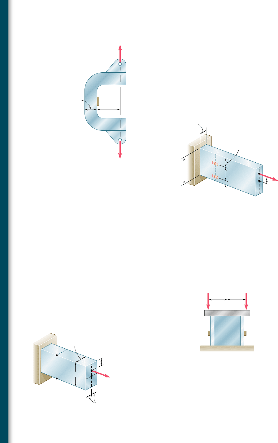
4.121 The C-shaped steel bar is used as a dynamometer to determine the
magnitude P of the forces shown. Knowing that the cross section
of the bar is a square of side 40 mm and that the strain on the inner
edge was measured and found to be 450 m, determine the magni-
tude P of the forces. Use E 5 200 GPa.
4.122 An eccentric force P is applied as shown to a steel bar of 25 3 90-mm
cross section. The strains at A and B have been measured and
found to be
P
A
5 1350 m P
B
5 270 m
Knowing that E 5 200 GPa, determine (a) the distance d, (b) the
magnitude of the force P.
40 mm
80 mm
P
'
P
Fig. P4.121
30 mm
45 mm
15 mm
90 mm
25 mm
d
A
B
P
Fig. P4.122
4.123 Solve Prob. 4.122, assuming that the measured strains are
P
A
5 1600 m P
B
5 1420 m
4.124 A short length of a W8 3 31 rolled-steel shape supports a rigid
plate on which two loads P and Q are applied as shown. The strains
at two points A and B on the centerline of the outer faces of the
flanges have been measured and found to be
P
A
5 2550 3 10
26
in./in. P
B
5 2680 3 10
26
in./in.
Knowing that E 5 29 3 10
6
psi, determine the magnitude of each
load.
BA
4.5 in.
P Q
4.5 in.
Fig. P4.124
b 40 mm
a 25 mm
20 mm
A
D
C
B
d
P
Fig. P4.126
4.125 Solve Prob. 4.124, assuming that the measured strains are
P
A
5 135 3 10
26
in./in. and P
B
5 2450 3 10
26
in./in.
4.126 The eccentric axial force P acts at point D, which must be located
25 mm below the top surface of the steel bar shown. For P 5 60 kN,
determine (a) the depth d of the bar for which the tensile stress at
point A is maximum, (b) the corresponding stress at point A.
bee80288_ch04_220-313.indd Page 278 11/11/10 3:03:18 PM user-f499bee80288_ch04_220-313.indd Page 278 11/11/10 3:03:18 PM user-f499 /Users/user-f499/Desktop/Temp Work/Don't Delete Job/MHDQ251:Beer:201/ch04/Users/user-f499/Desktop/Temp Work/Don't Delete Job/MHDQ251:Beer:201/ch04
Apago PDF Enhancer
279
4.13 UNSYMMETRIC BENDING
Our analysis of pure bending has been limited so far to members
possessing at least one plane of symmetry and subjected to couples
acting in that plane. Because of the symmetry of such members and
of their loadings, we concluded that the members would remain
symmetric with respect to the plane of the couples and thus bend
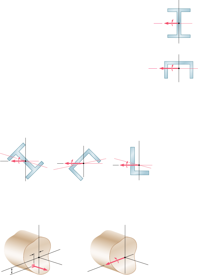
in that plane (Sec. 4.3). This is illustrated in Fig. 4.49; part a shows
the cross section of a member possessing two planes of symmetry,
one vertical and one horizontal, and part b the cross section of a
member with a single, vertical plane of symmetry. In both cases the
couple exerted on the section acts in the vertical plane of symmetry
of the member and is represented by the horizontal couple vector
M, and in both cases the neutral axis of the cross section is found
to coincide with the axis of the couple.
Let us now consider situations where the bending couples do
not act in a plane of symmetry of the member, either because they
act in a different plane, or because the member does not possess any
plane of symmetry. In such situations, we cannot assume that the
member will bend in the plane of the couples. This is illustrated in
Fig. 4.50. In each part of the figure, the couple exerted on the sec-
tion has again been assumed to act in a vertical plane and has been
represented by a horizontal couple vector M. However, since the
vertical plane is not a plane of symmetry, we cannot expect the mem-
ber to bend in that plane, or the neutral axis of the section to coincide
with the axis of the couple.
4.13 Unsymmetric Bending
M
z
y
N.A. C
(a)
(b)
M
z
y
N.A.
C
Fig. 4.49 Moment in
plane of symmetry.
(a)
M
z
y
N.A.
C
Fig. 4.50 Moment not in plane of symmetry.
(b)
M
z
y
N.A.
C
(c)
M
z
y
N.A.
C
We propose to determine the precise conditions under which the
neutral axis of a cross section of arbitrary shape coincides with the axis
of the couple M representing the forces acting on that section. Such a
section is shown in Fig. 4.51, and both the couple vector M and the
z
N.A.
C
dA
x
y
y
z
x
z
C
x
y
M
=
Fig. 4.51 Section with arbitrary shape.
bee80288_ch04_220-313.indd Page 279 10/26/10 4:31:52 PM user-f499bee80288_ch04_220-313.indd Page 279 10/26/10 4:31:52 PM user-f499 /Volumes/201/MHDQ251/bee80288_disk1of1/0073380288/bee80288_pagefiles/Volumes/201/MHDQ251/bee80288_disk1of1/0073380288/bee80288_pagefiles
Apago PDF Enhancer
280
Pure Bending
neutral axis have been assumed to be directed along the z axis. We
recall from Sec. 4.2 that, if we then express that the elementary internal
forces s
x
dA form a system equivalent to the couple M, we obtain
x components: es
x
dA 5 0 (4.1)
moments about y axis: ezs
x
dA 5 0 (4.2)
moments about z axis: e(2ys
x
dA) 5 M (4.3)
As we saw earlier, when all the stresses are within the proportional
limit, the first of these equations leads to the requirement that the
neutral axis be a centroidal axis, and the last to the fundamental
relation s
x
5 2MyyI. Since we had assumed in Sec. 4.2 that the
cross section was symmetric with respect to the y axis, Eq. (4.2) was
dismissed as trivial at that time. Now that we are considering a cross
section of arbitrary shape, Eq. (4.2) becomes highly significant.
Assuming the stresses to remain within the proportional limit of the
material, we can substitute s
x
5 2s
m
yyc into Eq. (4.2) and write
#
z a2
s
m
y
c
b
dA 5 0or
e
yz dA 5 0 (4.51)
The integral eyzdA represents the product of inertia I
yz
of the cross
section with respect to the y and z axes, and will be zero if these
axes are the principal centroidal axes of the cross section.† We thus
conclude that the neutral axis of the cross section will coincide with
the axis of the couple M representing the forces acting on that sec-
tion if, and only if, the couple vector M is directed along one of the
principal centroidal axes of the cross section.
We note that the cross sections shown in Fig. 4.49 are sym-
metric with respect to at least one of the coordinate axes. It follows
that, in each case, the y and z axes are the principal centroidal axes
of the section. Since the couple vector M is directed along one of
the principal centroidal axes, we verify that the neutral axis will coin-
cide with the axis of the couple. We also note that, if the cross sec-
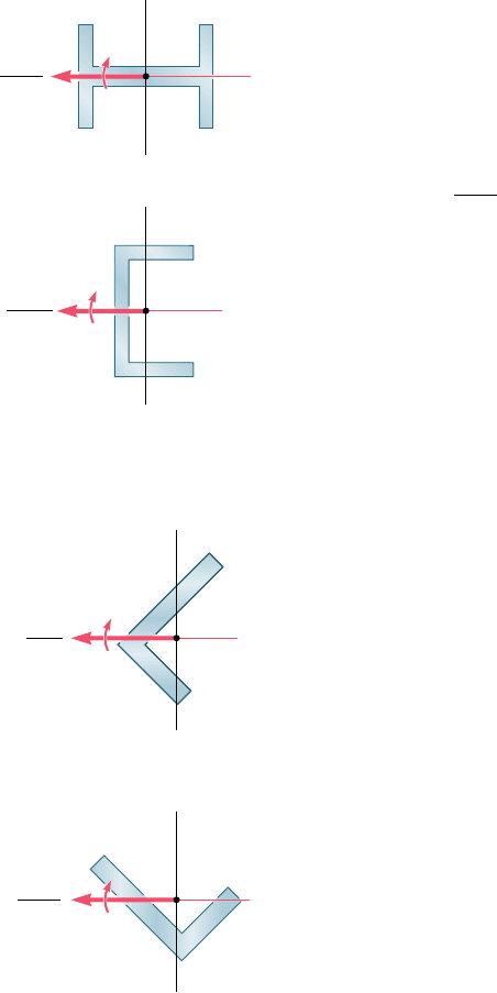
tions are rotated through 908 (Fig. 4.52), the couple vector M will
still be directed along a principal centroidal axis, and the neutral axis
will again coincide with the axis of the couple, even though in case
b the couple does not act in a plane of symmetry of the member.
In Fig. 4.50, on the other hand, neither of the coordinate axes
is an axis of symmetry for the sections shown, and the coordinate
axes are not principal axes. Thus, the couple vector M is not directed
along a principal centroidal axis, and the neutral axis does not coin-
cide with the axis of the couple. However, any given section possesses
principal centroidal axes, even if it is unsymmetric, as the section
shown in Fig. 4.50c, and these axes may be determined analytically
or by using Mohr’s circle.† If the couple vector M is directed along
one of the principal centroidal axes of the section, the neutral axis
will coincide with the axis of the couple (Fig. 4.53) and the equations
†See Ferdinand P. Beer and E. Russell Johnston, Jr., Mechanics for Engineers, 5th ed.,
McGraw-Hill, New York, 2008, or Vector Mechanics for Engineers, 9th ed., McGraw-Hill,
New York, 2010, Secs. 9.8–9.10.
(a)
(b)
M
N.A.
N.A.
z
y
C
M
z
y
C
Fig. 4.52 Moment on
principal centroidal axis.
N.A.
(a)
M
z
y
C
N.A.
(b)
M
z
y
C
Fig. 4.53 Moment not on
principal centroidal axis.
bee80288_ch04_220-313.indd Page 280 10/26/10 4:32:00 PM user-f499bee80288_ch04_220-313.indd Page 280 10/26/10 4:32:00 PM user-f499 /Volumes/201/MHDQ251/bee80288_disk1of1/0073380288/bee80288_pagefiles/Volumes/201/MHDQ251/bee80288_disk1of1/0073380288/bee80288_pagefiles
Apago PDF Enhancer
281
derived in Secs. 4.3 and 4.4 for symmetric members can be used to
determine the stresses in this case as well.
As you will see presently, the principle of superposition can be
used to determine stresses in the most general case of unsymmetric
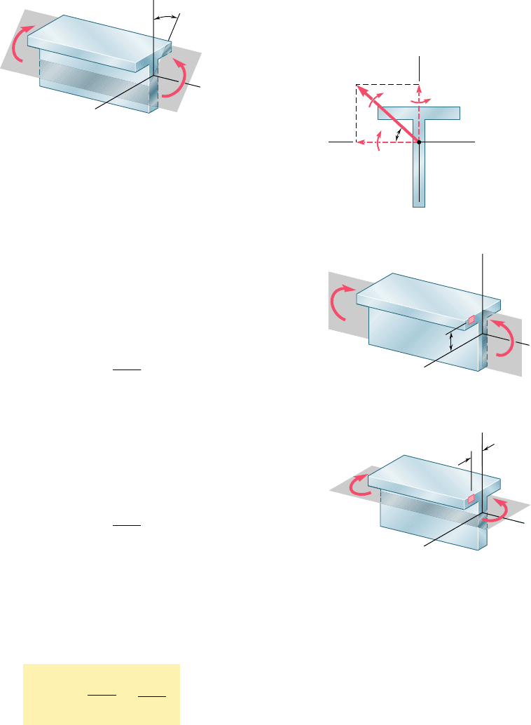
bending. Consider first a member with a vertical plane of symmetry,
which is subjected to bending couples M and M9 acting in a plane
forming an angle u with the vertical plane (Fig. 4.54). The couple
4.13 Unsymmetric Bending
M
x
z
y
M'
Fig. 4.54 Unsymmetric bending.
M
M
y
M
z
y
z
C
Fig. 4.55
vector M representing the forces acting on a given cross section will
form the same angle u with the horizontal z axis (Fig. 4.55). Resolv-
ing the vector M into component vectors M
z
and M
y
along the z and
y axes, respectively, we write
M
z
5 M cos uM
y
5 M sin u (4.52)
Since the y and z axes are the principal centroidal axes of the cross
section, we can use Eq. (4.16) to determine the stresses resulting
from the application of either of the couples represented by M
z
and
M
y
. The couple M
z
acts in a vertical plane and bends the member
in that plane (Fig. 4.56). The resulting stresses are
s
x
52
M
z
y
I
z
(4.53)
where I
z
is the moment of inertia of the section about the principal
centroidal z axis. The negative sign is due to the fact that we have
compression above the xz plane (y . 0) and tension below (y , 0).
On the other hand, the couple M
y
acts in a horizontal plane and
bends the member in that plane (Fig. 4.57). The resulting stresses
are found to be
s
x
51
M
y
z
I
y
(4.54)
where I
y
is the moment of inertia of the section about the principal
centroidal y axis, and where the positive sign is due to the fact that
we have tension to the left of the vertical xy plane (z . 0) and com-
pression to its right (z , 0). The distribution of the stresses caused
by the original couple M is obtained by superposing the stress dis-
tributions defined by Eqs. (4.53) and (4.54), respectively. We have
s
x
52
M
z
y
I
z
1
M
y
z
I
y
(4.55)
M'
z
z
y
M
z
x
y
Fig. 4.56
M'
y
z
z
M
y
x
y
Fig. 4.57
bee80288_ch04_220-313.indd Page 281 10/27/10 5:46:23 PM user-f499bee80288_ch04_220-313.indd Page 281 10/27/10 5:46:23 PM user-f499 /Users/user-f499/Desktop/Temp Work/Don't Delete Job/MHDQ251:Beer:201/ch04/Users/user-f499/Desktop/Temp Work/Don't Delete Job/MHDQ251:Beer:201/ch04
Apago PDF Enhancer
282
Pure Bending
M
N. A.
C
y
z
Fig. 4.59
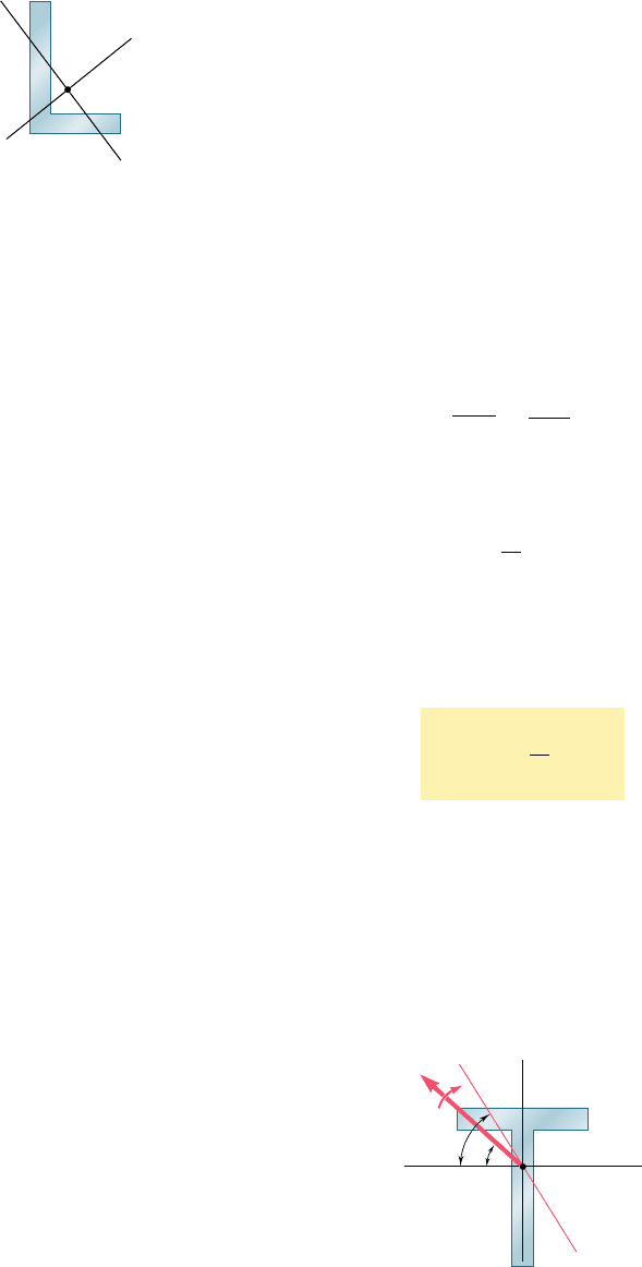
We note that the expression obtained can also be used to com-
pute the stresses in an unsymmetric section, such as the one shown
in Fig. 4.58, once the principal centroidal y and z axes have been
determined. On the other hand, Eq. (4.55) is valid only if the condi-
tions of applicability of the principle of superposition are met. In
other words, it should not be used if the combined stresses exceed
the proportional limit of the material, or if the deformations caused
by one of the component couples appreciably affect the distribution
of the stresses due to the other.
Equation (4.55) shows that the distribution of stresses caused
by unsymmetric bending is linear. However, as we have indicated
earlier in this section, the neutral axis of the cross section will not,
in general, coincide with the axis of the bending couple. Since the
normal stress is zero at any point of the neutral axis, the equation
defining that axis can be obtained by setting s
x
5 0 in Eq. (4.55).
We write
2
M
z
y
I
z
1
M
y
z
I
y
5 0
or, solving for y and substituting for M
z
and M
y
from Eqs. (4.52),
y
5 a
I
z
I
y
tan ub z (4.56)
The equation obtained is that of a straight line of slope m 5 (I
z
yI
y
)
tan u. Thus, the angle f that the neutral axis forms with the z axis
(Fig. 4.59) is defined by the relation
tan f 5
I
z
I
y
tan u (4.57)
where u is the angle that the couple vector M forms with the same
axis. Since I
z
and I
y
are both positive, f and u have the same sign.
Furthermore, we note that f . u when I
z
. I
y
, and f , u when
I
z
, I
y
. Thus, the neutral axis is always located between the couple
vector M and the principal axis corresponding to the minimum
moment of inertia.
C
y
z
Fig. 4.58 Unsymmetric
cross section.
bee80288_ch04_220-313.indd Page 282 10/26/10 4:32:18 PM user-f499bee80288_ch04_220-313.indd Page 282 10/26/10 4:32:18 PM user-f499 /Volumes/201/MHDQ251/bee80288_disk1of1/0073380288/bee80288_pagefiles/Volumes/201/MHDQ251/bee80288_disk1of1/0073380288/bee80288_pagefiles
Apago PDF Enhancer
283
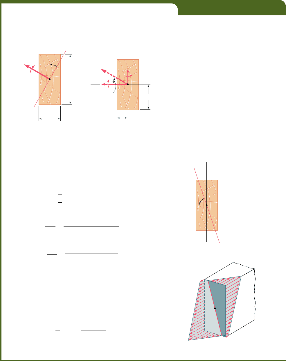
EXAMPLE 4.08
A 1600-lb ? in. couple is applied to a wooden beam, of rectangular cross
section 1.5 by 3.5 in., in a plane forming an angle of 308 with the vertical
(Fig. 4.60). Determine (a) the maximum stress in the beam, (b) the angle
that the neutral surface forms with the horizontal plane.
C
30
3.5 in.
1.5 in.
1600 lb · in.
Fig. 4.60
M
z
ED
C
A
B
y
z
30
1.75 in.
0.75 in.
1600 lb · in.
Fig. 4.61
(a) Maximum Stress. The components M
z
and M
y
of the couple
vector are first determined (Fig. 4.61):
M
z
5 11600 lb ? in.2 cos 30° 5 1386 lb ? in.
M
y
5 11600 lb ? in.2 sin 30° 5 800 lb ? in.
We also compute the moments of inertia of the cross section with
respect to the z and y axes:
I
z
5
1
12
11.5 in.2 13.5 in.2
3
5 5.359 in
4
I
y
5
1
12
13.5 in.2 11.5 in.2
3
5 0.9844 in
4
The largest tensile stress due to M
z
occurs along AB and is
s
1
5
M
z
y
I
z
5
11386 lb ? in.2
11.75 in.2
5.359 in
4
5 452.6 psi
The largest tensile stress due to M
y
occurs along AD and is
s
2
5
M
y
z
I
y
5
1800 lb ? in.2
10.75 in.2
0.9844 in
4
5 609.5 psi
The largest tensile stress due to the combined loading, therefore, occurs
at A and is
s
max
5 s
1
1 s
2
5 452.6 1 609.5 5 1062 psi
The largest compressive stress has the same magnitude and occurs at E.
(b) Angle of Neutral Surface with Horizontal Plane. The
angle f that the neutral surface forms with the horizontal plane (Fig. 4.62)
is obtained from Eq. (4.57):
tan f 5
I
z
I
y
tan u 5
5.359 in
4
0.9844 in
4
tan 30° 5 3.143
f 5 72.4°
The distribution of the stresses across the section is shown in Fig. 4.63.
N. A.
E
C
D
AB
y
z
Fig. 4.62
D
E
B
1062 psi
1062 psi
Neutral axis
A
C
Fig. 4.63
bee80288_ch04_220-313.indd Page 283 10/26/10 4:32:24 PM user-f499bee80288_ch04_220-313.indd Page 283 10/26/10 4:32:24 PM user-f499 /Volumes/201/MHDQ251/bee80288_disk1of1/0073380288/bee80288_pagefiles/Volumes/201/MHDQ251/bee80288_disk1of1/0073380288/bee80288_pagefiles
Apago PDF Enhancer
284
Pure Bending
4.14 GENERAL CASE OF ECCENTRIC AXIAL LOADING
In Sec. 4.12 you analyzed the stresses produced in a member by an
eccentric axial load applied in a plane of symmetry of the member.
You will now study the more general case when the axial load is not
applied in a plane of symmetry.
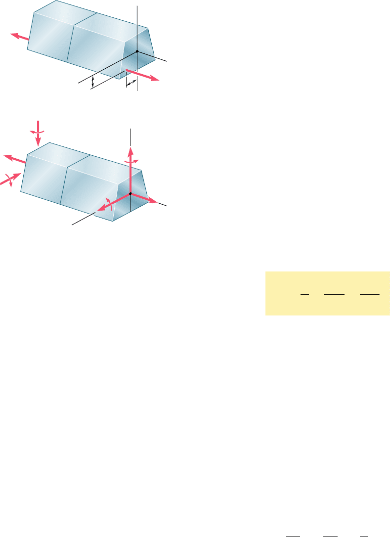
Consider a straight member AB subjected to equal and oppo-
site eccentric axial forces P and P9 (Fig. 4.64a), and let a and b
denote the distances from the line of action of the forces to the
principal centroidal axes of the cross section of the member. The
eccentric force P is statically equivalent to the system consisting of
a centric force P and of the two couples M
y
and M
z
of moments M
y
5 Pa and M
z
5 Pb represented in Fig. 4.64b. Similarly, the eccentric
force P9 is equivalent to the centric force P9 and the couples M9
y
and M9
z
.
By virtue of Saint-Venant’s principle (Sec. 2.17), we can replace
the original loading of Fig. 4.64a by the statically equivalent loading
of Fig. 4.64b in order to determine the distribution of stresses in a
section S of the member, as long as that section is not too close to
either end of the member. Furthermore, the stresses due to the
loading of Fig. 4.64b can be obtained by superposing the stresses
corresponding to the centric axial load P and to the bending couples
M
y
and M
z
, as long as the conditions of applicability of the principle
of superposition are satisfied (Sec. 2.12). The stresses due to the
centric load P are given by Eq. (1.5), and the stresses due to the
bending couples by Eq. (4.55), since the corresponding couple vec-
tors are directed along the principal centroidal axes of the section.
We write, therefore,
s
x
5
P
A
2
M
z
y
I
z
1
M
y
z
I
y
(4.58)
where y and z are measured from the principal centroidal axes of
the section. The relation obtained shows that the distribution of
stresses across the section is linear.
In computing the combined stress s
x
from Eq. (4.58), care
should be taken to correctly determine the sign of each of the three
terms in the right-hand member, since each of these terms can be
positive or negative, depending upon the sense of the loads P and
P9 and the location of their line of action with respect to the principal
centroidal axes of the cross section. Depending upon the geometry
of the cross section and the location of the line of action of P and
P9, the combined stresses s
x
obtained from Eq. (4.58) at various
points of the section may all have the same sign, or some may be
positive and others negative. In the latter case, there will be a line
in the section, along which the stresses are zero. Setting s
x
5 0 in
Eq. (4.58), we obtain the equation of a straight line, which represents
the neutral axis of the section:
M
z
I
z
y 2
M
y
I
y
z 5
P
A
B
A
S
x
C
a
b
z
y
P'
P
P'
(a)
B
A
S
x
y
C
z
M'
z
M
z
M'
y
M
y
P
(b)
Fig. 4.64 Eccentric axial loading.
bee80288_ch04_220-313.indd Page 284 10/27/10 5:46:24 PM user-f499bee80288_ch04_220-313.indd Page 284 10/27/10 5:46:24 PM user-f499 /Users/user-f499/Desktop/Temp Work/Don't Delete Job/MHDQ251:Beer:201/ch04/Users/user-f499/Desktop/Temp Work/Don't Delete Job/MHDQ251:Beer:201/ch04
Apago PDF Enhancer
285
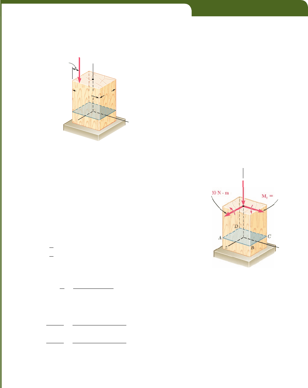
EXAMPLE 4.09
A vertical 4.80-kN load is applied as shown on a wooden post of rectan-
gular cross section, 80 by 120 mm (Fig. 4.65). (a) Determine the stress
at points A, B, C, and D. (b) Locate the neutral axis of the cross
section.
4.80 kN
35 mm
120 mm
80 mm
D
C
B
A
y
z
x
Fig. 4.65
P
4
.
80 kN
M
z
12
192
N
·
m
y
x
Fig. 4.66
(a) Stresses. The given eccentric load is replaced by an equiva-
lent system consisting of a centric load P and two couples M
x
and M
z
represented by vectors directed along the principal centroidal axes of the
section (Fig. 4.66). We have
M
x
5 14.80 kN2140 mm25 192 N ? m
M
z
5 14.80 kN2160 mm 2 35 mm25 120 N ? m
We also compute the area and the centroidal moments of inertia of the
cross section:
A
5 10.080 m210.120 m25 9.60 3 10
23
m
2
I
x
5
1
12
10.120 m210.080 m2
3
5 5.12 3 10
26
m
4
I
z
5
1
12
10.080 m210.120 m2
3
5 11.52 3 10
26
m
4
The stress s
0
due to the centric load P is negative and uniform across
the section. We have
s
0
5
P
A
5
24.80 kN
9
.
60 3 10
23
m
2
520.5 MPa
The stresses due to the bending couples M
x
and M
z
are linearly distrib-
uted across the section, with maximum values equal, respectively, to
s
1
5
M
x
z
max
I
x
5
1192 N ? m2140 mm
2
5.12 3 10
26
m
4
5 1.5 MPa
s
2
5
M
z
x
max
I
z
5
1120 N ? m2160 mm
2
11.52 3 10
26
m
4
5 0.625 MPa
The stresses at the corners of the section are
s
y
5 s
0
6 s
1
6 s
2
where the signs must be determined from Fig. 4.66. Noting that the
stresses due to M
x
are positive at C and D, and negative at A and B, and
bee80288_ch04_220-313.indd Page 285 10/26/10 4:32:39 PM user-f499bee80288_ch04_220-313.indd Page 285 10/26/10 4:32:39 PM user-f499 /Volumes/201/MHDQ251/bee80288_disk1of1/0073380288/bee80288_pagefiles/Volumes/201/MHDQ251/bee80288_disk1of1/0073380288/bee80288_pagefiles
Apago PDF Enhancer
that the stresses due to M
z
are positive at B and C, and negative at A and
D, we obtain
s
A
520.5 2 1.5 2 0.625 522.625 MPa
s
B
520.5 2 1.5 1 0.625 521.375 MPa
s
C
520.5 1 1.5 1 0.625 511.625 MPa
s
D
520.5 1 1.5 2 0.625 510.375 MPa
80 mm
80 mm
0.375 MPa
1.625 MPa
1.375 MPa
2.625 MPa
C
A
D
H
G
B
(a)(b)
Fig. 4.67
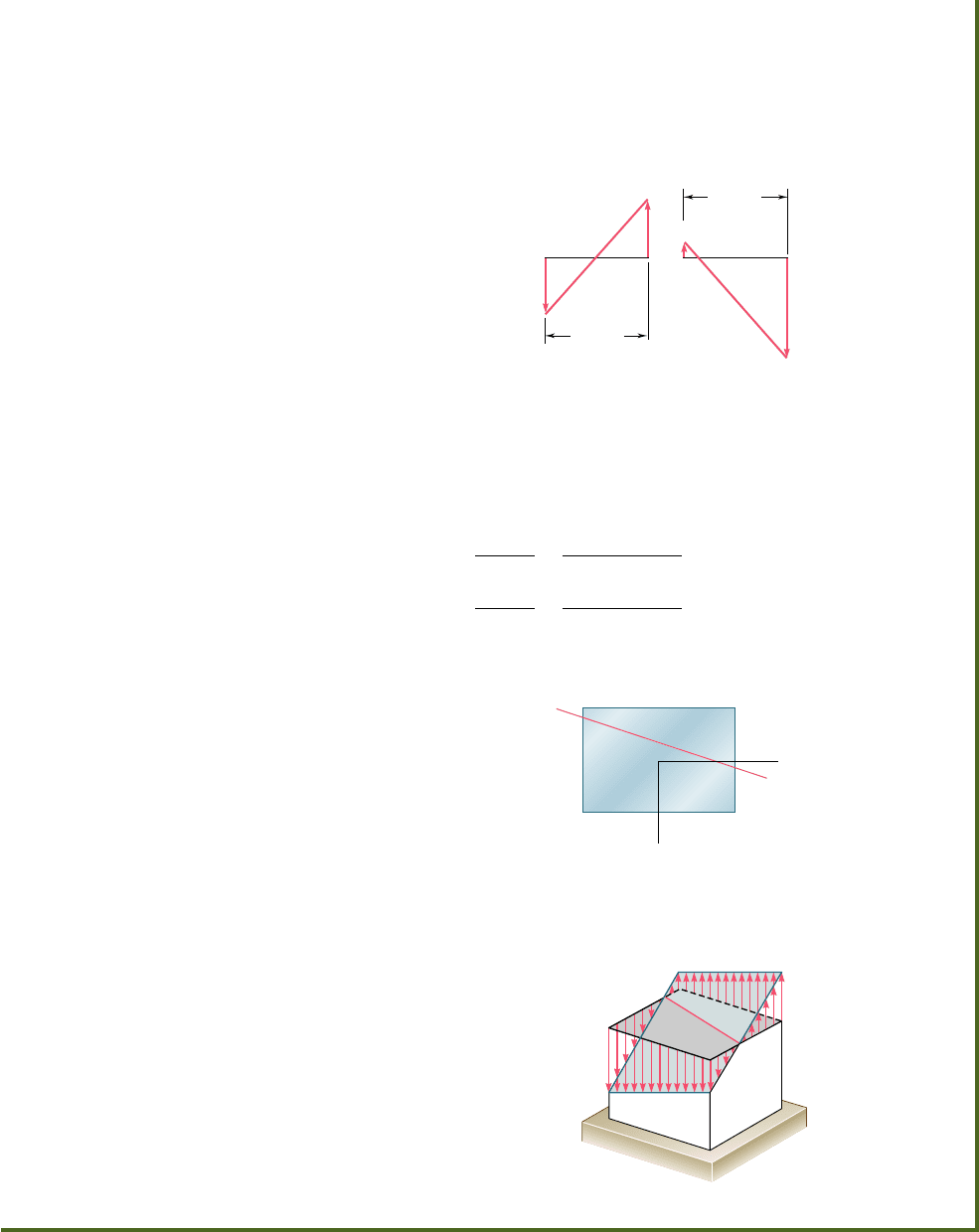
(b) Neutral Axis. We note that the stress will be zero at a point
G between B and C, and at a point H between D and A (Fig. 4.67). Since
the stress distribution is linear, we write
B
G
80 mm
5
1.375
1
.
625 1 1
.
375
BG 5 36.7 mm
H
A
80 mm
5
2.625
2
.
625 1 0
.
375
HA 5 70 mm
The neutral axis can be drawn through points G and H (Fig. 4.68).
C
A
D
H
G
x
z
O
B
Neutral axis
Fig. 4.68
C
H
B
A
0.375 MPa
2.625 MPa
Neutral
axis
1.625 MP
a
1.375 MPa
G
Fig. 4.69
The distribution of the stresses across the section is shown in Fig. 4.69.
286
bee80288_ch04_220-313.indd Page 286 10/26/10 4:32:47 PM user-f499bee80288_ch04_220-313.indd Page 286 10/26/10 4:32:47 PM user-f499 /Volumes/201/MHDQ251/bee80288_disk1of1/0073380288/bee80288_pagefiles/Volumes/201/MHDQ251/bee80288_disk1of1/0073380288/bee80288_pagefiles
