Beer F.P., Johnston E.R., DeWolf J.T., Mazurek D.F. Mechanics of Materials
Подождите немного. Документ загружается.

Apago PDF Enhancer
257
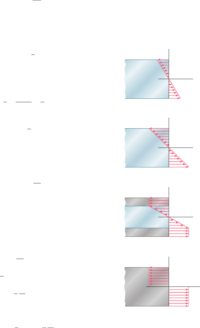
As long as the normal stress s
x
does not exceed the yield strength
s
Y
, Hooke’s law applies, and the stress distribution across the section
is linear (Fig. 4.36a). The maximum value of the stress is
s
m
5
M
c
I
(4.15)
As the bending moment increases, s
m
eventually reaches the value
s
Y
(Fig. 4.36b). Substituting this value into Eq. (4.15), and solving
for the corresponding value of M, we obtain the value M
Y
of the
bending moment at the onset of yield:
M
Y
5
I
c
s
Y
(4.33)
The moment M
Y
is referred to as the maximum elastic moment, since
it is the largest moment for which the deformation remains fully elas-
tic. Recalling that, for the rectangular cross section considered here,
I
c
5
b12c2
3
12
c
5
2
3
bc
2
(4.34)
we write
M
Y
5
2
3
bc
2
s
Y
(4.35)
As the bending moment further increases, plastic zones develop in
the member, with the stress uniformly equal to 2s
Y
in the upper zone,
and to 1s
Y
in the lower zone (Fig. 4.36c). Between the plastic zones,
an elastic core subsists, in which the stress s
x
varies linearly with y,
s
x
52
s
Y
y
Y
y
(4.36)
where y
Y
represents half the thickness of the elastic core. As M
increases, the plastic zones expand until, at the limit, the deformation
is fully plastic (Fig. 4.36d).
Equation (4.31) will be used to determine the value of the
bending moment M corresponding to a given thickness 2y
Y
of the
elastic core. Recalling that s
x
is given by Eq. (4.36) for 0 # y # y
Y
,
and is equal to 2s
Y
for y
Y
# y # c, we write
M 522b
#
y
Y
0
ya2
s
Y
y
Y
yb dy 2 2b
#
c
y
Y
y12s
Y
2
dy
5
2
3
by
2
Y
s
Y
1 bc
2
s
Y
2 by
2
Y
s
Y
M 5 bc
2
s
Y
a
1 2
1
3
y
2
Y
c
2
b
(4.37)
or, in view of Eq. (4.35),
M 5
3
2
M
Y
a
1 2
1
3
y
2
Y
c
2
b
(4.38)
4.9 Members Made of an
Elastoplastic Material
ELASTIC
y
c
c
x
max
m
(a) MM
ELASTIC
y
c
x
max
m
(b) MM
ELASTIC
PLASTIC
PLASTIC
y
c
c
x
max
(c) MM
PLASTIC
y
c
c
x
(d) MM
p
c
Fig. 4.36 Bending stress distribution
in beam for different moments.
bee80288_ch04_220-313.indd Page 257 11/11/10 3:03:14 PM user-f499bee80288_ch04_220-313.indd Page 257 11/11/10 3:03:14 PM user-f499 /Users/user-f499/Desktop/Temp Work/Don't Delete Job/MHDQ251:Beer:201/ch04/Users/user-f499/Desktop/Temp Work/Don't Delete Job/MHDQ251:Beer:201/ch04
Apago PDF Enhancer
258
Pure Bending
where M
Y
is the maximum elastic moment. Note that as y
Y
approaches
zero, the bending moment approaches the limiting value
M
p
5
3
2
M
Y
(4.39)
This value of the bending moment, which corresponds to a fully
plastic deformation (Fig. 4.36d), is called the plastic moment of the
member considered. Note that Eq. (4.39) is valid only for a rectan-
gular member made of an elastoplastic material.
You should keep in mind that the distribution of strain across the
section remains linear after the onset of yield. Therefore, Eq. (4.8) of
Sec. 4.3 remains valid and can be used to determine the half-thickness
y
Y
of the elastic core. We have
y
Y
5 P
Y
r (4.40)
where P
Y
is the yield strain and r the radius of curvature correspond-
ing to a bending moment M $ M
Y
. When the bending moment is
equal to M
Y
, we have y
Y
5 c and Eq. (4.40) yields
c 5 P
Y
r
Y
(4.41)
where r
Y
is the radius of curvature corresponding to the maximum
elastic moment M
Y
. Dividing (4.40) by (4.41) member by member,
we obtain the relation†
y
Y
c
5
r
r
Y
(4.42)
Substituting for y
Y
yc from (4.42) into Eq. (4.38), we express the
bending moment M as a function of the radius of curvature r of the
neutral surface:
M 5
3
2
M
Y
a1 2
1
3
r
2
r
2
Y
b
(4.43)
Note that Eq. (4.43) is valid only after the onset of yield, i.e., for
values of M larger than M
Y
. For M , M
Y
, Eq. (4.21) of Sec. 4.4
should be used.
We observe from Eq. (4.43) that the bending moment reaches
the value M
p
5
3
2
M
Y
only when r 5 0. Since we clearly cannot have
a zero radius of curvature at every point of the neutral surface, we
conclude that a fully plastic deformation cannot develop in pure bend-
ing. As you will see in Chap. 5, however, such a situation may occur
at one point in the case of a beam under a transverse loading.
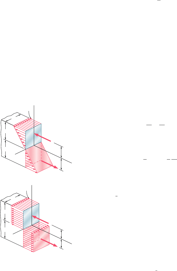
The stress distributions in a rectangular member corresponding
respectively to the maximum elastic moment M
Y
and to the limiting
case of the plastic moment M
p
have been represented in three
dimensions in Fig. 4.37. Since, in both cases, the resultants of the
elementary tensile and compressive forces must pass through the
centroids of the volumes representing the stress distributions and be
equal in magnitude to these volumes, we check that
R
Y
5
1
2
bcs
Y
†Equation (4.42) applies to any member made of any ductile material with a well-defined
yield point, since its derivation is independent of the shape of the cross section and of the
shape of the stress-strain diagram beyond the yield point.
b
c
c
z
2c/3
2c/3
Y
Y
m
x
R'
Y
b
c
c
z
R
p
c/2
c/2
Y
Y
x
R'
p
(a)
(b)
y
y
R
Y
Fig. 4.37 Stress distributions in beam
at maximum elastic moment and at
plastic moment.
bee80288_ch04_220-313.indd Page 258 10/27/10 5:46:17 PM user-f499bee80288_ch04_220-313.indd Page 258 10/27/10 5:46:17 PM user-f499 /Users/user-f499/Desktop/Temp Work/Don't Delete Job/MHDQ251:Beer:201/ch04/Users/user-f499/Desktop/Temp Work/Don't Delete Job/MHDQ251:Beer:201/ch04

Apago PDF Enhancer
259
and
R
p
5 bcs
Y
and that the moments of the corresponding couples are, respectively,
M
Y
5
1
4
3
c
2
R
Y
5
2
3
bc
2
s
Y
(4.44)
and
M
p
5 cR
p
5 bc
2
s
Y
(4.45)
We thus verify that, for a rectangular member, M
p
5
3
2
M
Y
as required
by Eq. (4.39).
For beams of nonrectangular cross section, the computation of
the maximum elastic moment M
Y
and of the plastic moment M
p
will
usually be simplified if a graphical method of analysis is used, as shown
in Sample Prob. 4.5. It will be found in this more general case that
the ratio k 5 M
p
yM
Y
is generally not equal to
3
2
. For structural shapes
such as wide-flange beams, for example, this ratio varies approximately
from 1.08 to 1.14. Because it depends only upon the shape of the cross
section, the ratio k 5 M
p
yM
Y
is referred to as the shape factor of the
cross section. We note that, if the shape factor k and the maximum
elastic moment M
Y
of a beam are known, the plastic moment M
p
of
the beam can be obtained by multiplying M
Y
by k:
M
p
5 kM
Y
(4.46)
The ratio M
p
ys
Y
obtained by dividing the plastic moment M
p
of a member by the yield strength s
Y
of its material is called the
plastic section modulus of the member and is denoted by Z. When
the plastic section modulus Z and the yield strength s
Y
of a beam
are known, the plastic moment M
p
of the beam can be obtained by
multiplying s
Y
by Z:
M
p
5 Zs
Y
(4.47)
Recalling from Eq. (4.18) that M
Y
5 Ss
Y
, and comparing this relation
with Eq. (4.47), we note that the shape factor k 5 M
p
yM
Y
of a given
cross section can be expressed as the ratio of the plastic and elastic
section moduli:
k
5
M
p
M
Y
5
Zs
Y
Ss
Y
5
Z
S
(4.48)
Considering the particular case of a rectangular beam of width
b and depth h, we note from Eqs. (4.45) and (4.47) that the plastic
section modulus of a rectangular beam is
Z 5
M
p
s
Y
5
bc
2
s
Y
s
Y
5 bc
2
5
1
4
bh
2
On the other hand, we recall from Eq. (4.19) of Sec. 4.4 that the
elastic section modulus of the same beam is
S 5
1
6
bh
2
Substituting into Eq. (4.48) the values obtained for Z and S, we verify
that the shape factor of a rectangular beam is
k
5
Z
S
5
1
4
bh
2
1
6
bh
2
5
3
2
4.9 Members Made of an
Elastoplastic Material
bee80288_ch04_220-313.indd Page 259 10/27/10 5:46:18 PM user-f499bee80288_ch04_220-313.indd Page 259 10/27/10 5:46:18 PM user-f499 /Users/user-f499/Desktop/Temp Work/Don't Delete Job/MHDQ251:Beer:201/ch04/Users/user-f499/Desktop/Temp Work/Don't Delete Job/MHDQ251:Beer:201/ch04
Apago PDF Enhancer
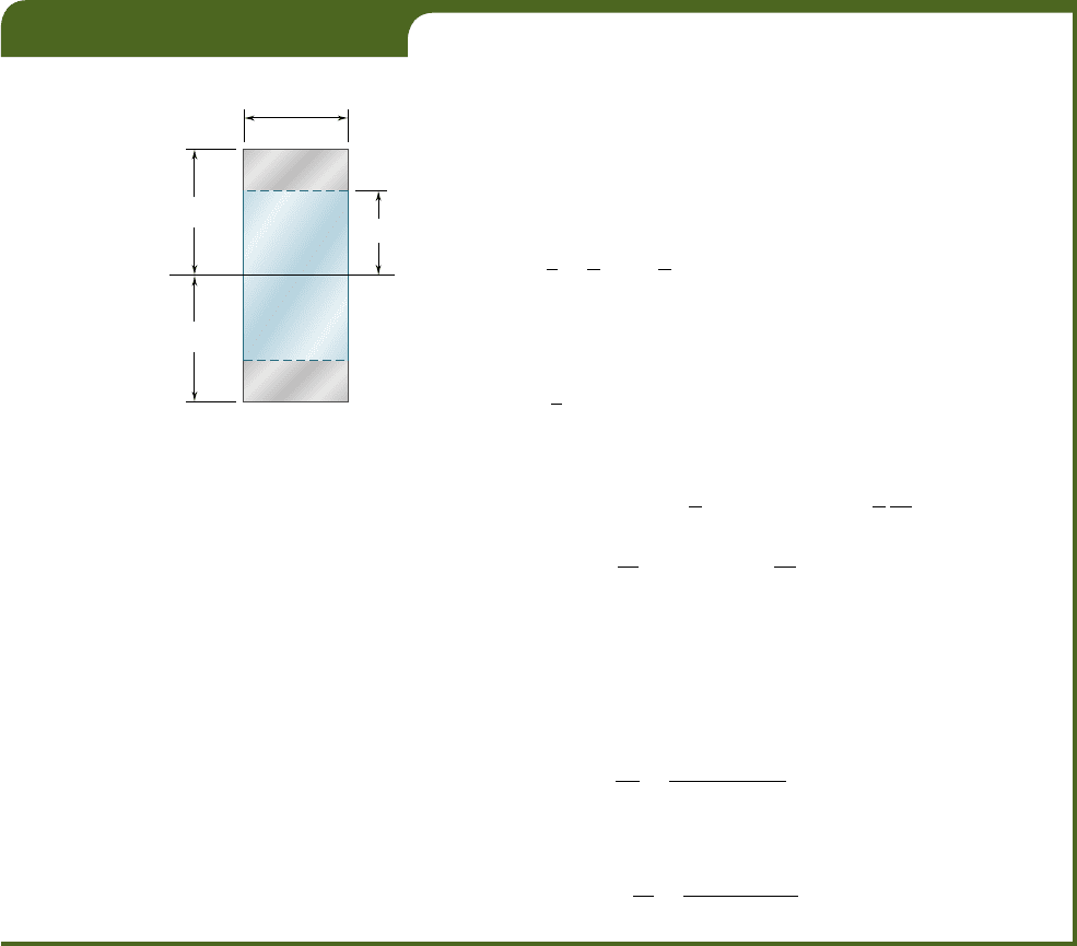
A member of uniform rectangular cross section 50 3 120 mm (Fig.
4.38) is subjected to a bending moment M 5 36.8 kN ? m. Assuming
that the member is made of an elastoplastic material with a yield
strength of 240 MPa and a modulus of elasticity of 200 GPa, determine
(a) the thickness of the elastic core, (b) the radius of curvature of the
neutral surface.
(a) Thickness of Elastic Core. We first determine the maximum
elastic moment M
Y
. Substituting the given data into Eq. (4.34), we have
I
c
5
2
3
bc
2
5
2
3
150 3 10
23
m2160 3 10
23
m2
2
5 120 3 10
2
6
m
3
and carrying this value, as well as s
Y
5 240 MPa, into Eq. (4.33),
M
Y
5
I
c
s
Y
5 1120 3 10
26
m
3
21240 MPa25 28.8 kN ? m
Substituting the values of M and M
Y
into Eq. (4.38), we have
36.8 kN ? m 5
3
2
128.8 kN ? m2
a
1 2
1
3
y
2
Y
c
2
b
a
y
Y
c
b
2
5 0.444
y
Y
c
5 0.666
and, since c 5 60 mm,
y
Y
5 0.666(60 mm) 5 40 mm
The thickness 2y
Y
of the elastic core is thus 80 mm.
(b) Radius of Curvature. We note that the yield strain is
P
Y
5
s
Y
E
5
240 3 10
6
Pa
200 3 10
9
P
a
5 1.2 3 10
23
Solving Eq. (4.40) for r and substituting the values obtained for y
Y
and
P
Y
, we write
r 5
y
Y
P
Y
5
40 3 10
2
3
m
1.2 3 10
23
5 33.3 m
EXAMPLE 4.05
c
60 mm
c
60 mm
b 50 mm
y
Y
Fig. 4.38
260
*4.10 PLASTIC DEFORMATIONS OF MEMBERS WITH
A SINGLE PLANE OF SYMMETRY
In our discussion of plastic deformations, we have assumed so far
that the member in bending had two planes of symmetry, one con-
taining the couples M and M9, and the other perpendicular to that
plane. Let us now consider the more general case when the member
possesses only one plane of symmetry containing the couples M and
M9. However, our analysis will be limited to the situation where the
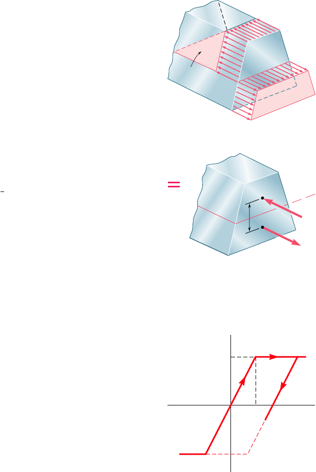
deformation is fully plastic, with the normal stress uniformly equal
to 2s
Y
above the neutral surface, and to 1s
Y
below that surface
(Fig. 4.39a).
As indicated in Sec. 4.8, the neutral axis cannot be assumed
to coincide with the centroidal axis of the cross section when the
bee80288_ch04_220-313.indd Page 260 11/11/10 3:03:14 PM user-f499bee80288_ch04_220-313.indd Page 260 11/11/10 3:03:14 PM user-f499 /Users/user-f499/Desktop/Temp Work/Don't Delete Job/MHDQ251:Beer:201/ch04/Users/user-f499/Desktop/Temp Work/Don't Delete Job/MHDQ251:Beer:201/ch04
Apago PDF Enhancer
261
cross section is not symmetric with respect to that axis. To locate
the neutral axis, we consider the resultant R
1
of the elementary
compressive forces exerted on the portion A
1
of the cross section
located above the neutral axis, and the resultant R
2
of the tensile
forces exerted on the portion A
2
located below the neutral axis
(Fig. 4.39b). Since the forces R
1
and R
2
form a couple equivalent
to the couple applied to the member, they must have the same
magnitude. We have therefore R
1
5 R
2
, or A
1
s
Y
5 A
2
s
Y
, from
which we conclude that A
1
5 A
2
. In other words, the neutral axis
divides the cross section into portions of equal areas. Note that the
axis obtained in this fashion will not, in general, be a centroidal axis
of the section.
We also observe that the lines of action of the resultants R
1
and
R
2
pass through the centroids C
1
and C
2
of the two portions we have
just defined. Denoting by d the distance between C
1
and C
2
, and by
A the total area of the cross section, we express the plastic moment
of the member as
M
p
5 1
1
2
As
Y
2 d
An example of the actual computation of the plastic moment of
a member with only one plane of symmetry is given in Sample
Prob. 4.6.
*4.11 RESIDUAL STRESSES
We saw in the preceding sections that plastic zones will develop in
a member made of an elastoplastic material if the bending moment
is large enough. When the bending moment is decreased back to
zero, the corresponding reduction in stress and strain at any given
point can be represented by a straight line on the stress-strain dia-
gram, as shown in Fig. 4.40. As you will see presently, the final value
of the stress at a point will not, in general, be zero. There will be a
residual stress at most points, and that stress may or may not have
the same sign as the maximum stress reached at the end of the load-
ing phase.
Since the linear relation between s
x
and P
x
applies at all
points of the member during the unloading phase, Eq. (4.16) can be
used to obtain the change in stress at any given point. In other words,
the unloading phase can be handled by assuming the member to be
fully elastic.
The residual stresses are obtained by applying the principle of
superposition in a manner similar to that described in Sec. 2.20 for
an axial centric loading and used again in Sec. 3.11 for torsion. We
consider, on one hand, the stresses due to the application of the
given bending moment M and, on the other, the reverse stresses due
to the equal and opposite bending moment 2M that is applied to
unload the member. The first group of stresses reflect the elastoplas-
tic behavior of the material during the loading phase, and the second
group the linear behavior of the same material during the unloading
phase. Adding the two groups of stresses, we obtain the distribution
of residual stresses in the member.
4.11 Residual Stresses
Y
Neutral
surface
(a)
(b)
R
2
C
1
C
2
A
2
A
1
d
R
1
N.A.
Y
Fig. 4.39 Nonsymmetrical beam
subject to plastic moment.
Y
Y
x
x
Y
Fig. 4.40 Elastoplastic material
stress-strain diagram.
bee80288_ch04_220-313.indd Page 261 10/26/10 4:29:34 PM user-f499bee80288_ch04_220-313.indd Page 261 10/26/10 4:29:34 PM user-f499 /Volumes/201/MHDQ251/bee80288_disk1of1/0073380288/bee80288_pagefiles/Volumes/201/MHDQ251/bee80288_disk1of1/0073380288/bee80288_pagefiles
Apago PDF Enhancer
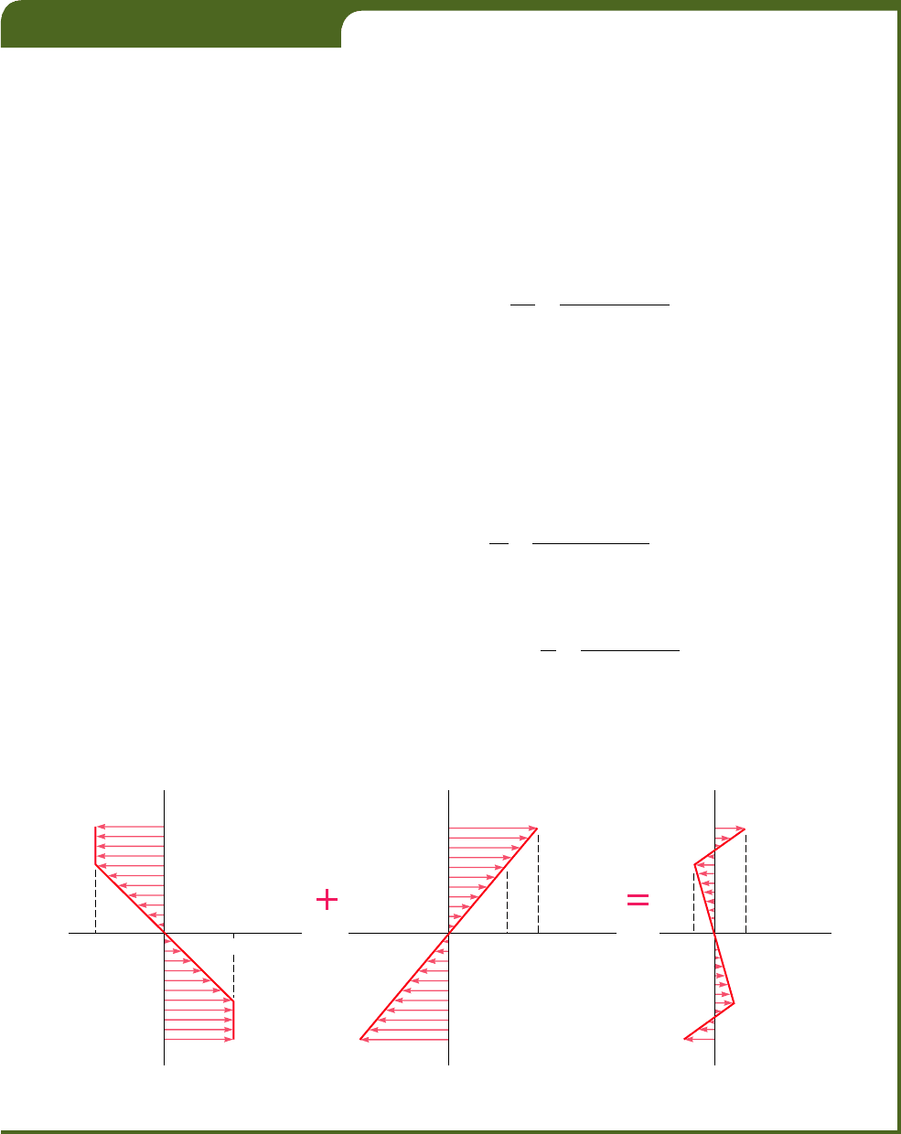
For the member of Example 4.05, determine (a) the distribution of the
residual stresses, (b) the radius of curvature, after the bending moment has
been decreased from its maximum value of 36.8 kN ? m back to zero.
(a) Distribution of Residual Stresses. We recall from Example
4.05 that the yield strength is s
Y
5 240 MPa and that the thickness of
the elastic core is
2
y
Y
5
80
mm. The distribution of the stresses in the
loaded member is thus as shown in Fig. 4.41a.
The distribution of the reverse stresses due to the opposite
36.8 kN ? m bending moment required to unload the member is linear
and as shown in Fig. 4.41b. The maximum stress s9
m
in that distribution
is obtained from Eq. (4.15). Recalling from Example 4.05 that Iyc 5
120 3 10
26
m
3
, we write
s¿
m
5
Mc
I
5
36.8
k
N ? m
120 3 10
26
m
3
5 306.7 MPa
Superposing the two distributions of stresses, we obtain the residual
stresses shown in Fig. 4.41c. We check that, even though the reverse
stresses exceed the yield strength s
Y
, the assumption of a linear distribu-
tion of the reverse stresses is valid, since they do not exceed 2s
Y
.
(b) Radius of Curvature after Unloading. We can apply Hooke’s
law at any point of the core |y| , 40 mm, since no plastic deformation
has occurred in that portion of the member. Thus, the residual strain at
the distance y 5 40 mm is
P
x
5
s
x
E
5
235.5 3 10
6
Pa
200 3 10
9
P
a
52177.5 3 10
26
Solving Eq. (4.8) for r and substituting the appropriate values of y and
P
x
, we write
r 52
y
P
x
5
40 3 10
2
3
m
177.5 3 10
26
5 225 m
The value obtained for r after the load has been removed represents a
permanent deformation of the member.
EXAMPLE 4.06
–40
40
60
40
204.5 306.7 –35.5
–40
–60
40
66.7 (MPa)
60 60
–60 –60
–240 240
y(mm) y(mm) y(mm)
(a)(b)(c)
'
m
x
x
(MPa)
x
Y
Fig. 4.41
262
bee80288_ch04_220-313.indd Page 262 11/11/10 3:03:15 PM user-f499bee80288_ch04_220-313.indd Page 262 11/11/10 3:03:15 PM user-f499 /Users/user-f499/Desktop/Temp Work/Don't Delete Job/MHDQ251:Beer:201/ch04/Users/user-f499/Desktop/Temp Work/Don't Delete Job/MHDQ251:Beer:201/ch04
Apago PDF Enhancer
263
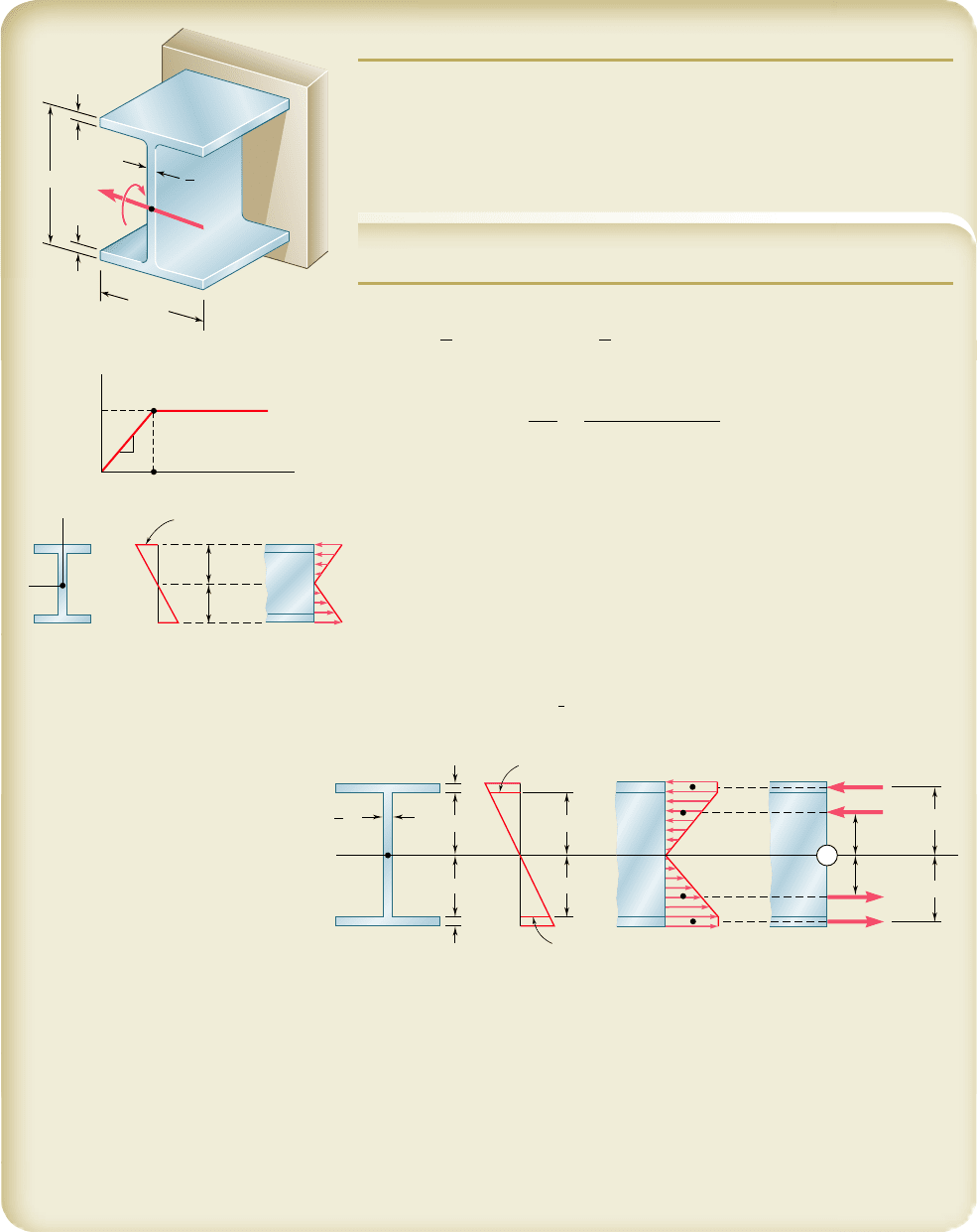
SAMPLE PROBLEM 4.5
Beam AB has been fabricated from a high-strength low-alloy steel that is
assumed to be elastoplastic with E 5 29 3 10
6
psi and s
Y
5 50 ksi. Neglect-
ing the effect of fillets, determine the bending moment M and the corre-
sponding radius of curvature (a) when yield first occurs, (b) when the flanges
have just become fully plastic.
SOLUTION
a. Onset of Yield. The centroidal moment of inertia of the section is
I 5
1
12
1
12 in.
21
16 in.
2
3
2
1
12
1
12 in. 2 0.75 in.
21
14 in.
2
3
5 1524 in
4
Bending Moment. For s
max
5 s
Y
5 50 ksi and c 5 8 in., we have
M
Y
5
s
Y
I
c
5
150 ksi211524 in
4
2
8
i
n.
M
Y
5 9525 kip ? in.
◀
Radius of Curvature. Noting that, at c 5 8 in., the strain is P
Y
5
s
Y
yE 5 (50 ksi)/(29 3 10
6
psi) 5 0.001724, we have from Eq. (4.41)
c 5 P
Y
r
Y
8 in. 5 0.001724r
Y
r
Y
5 4640 in.
◀
b. Flanges Fully Plastic. When the flanges have just become fully plas-
tic, the strains and stresses in the section are as shown in the figure below.
We replace the elementary compressive forces exerted on the top
flange and on the top half of the web by their resultants R
1
and R
2
, and
similarly replace the tensile forces by R
3
and R
4
.
R
1
5 R
4
5 (50 ksi)(12 in.)(1 in.) 5 600 kips
R
2
5 R
3
5
1
2
150 ksi217 in.210.75 in.25 131.3 kips
B
A
16 in.
1 in.
in.
1 in.
12 in.
3
4
M
y
z
C
E
O
50 ksi
1
Y
0.001724
8 in.
8 in.
Strain
distribution
Stress
distribution
Y
0.001724
Y
Y
C
in.
1 in.
Strain
distribution
Stress
distribution
Resultant
force
7 in.
7 in.
7 in.
7 in.
3
4
0.001724
Y
Y
50 ksi
R
4
R
1
R
2
R
3
Y
1 in.
7.5 in.
7.5 in.
4.67 in.
4.67 in.
z
Bending Moment. Summing the moments of R
1
, R
2
, R
3
, and R
4
about the z axis, we write
M 5 2[R
1
(7.5 in.) 1 R
2
(4.67 in.)]
5 2[(600)(7.5) 1 (131.3)(4.67)] M 5 10,230 kip ? in.
◀
Radius of Curvature. Since y
Y
5 7 in. for this loading, we have from
Eq. (4.40)
y
Y
5 P
Y
r 7 in. 5 (0.001724)r r 5 4060 in. 5 338 ft
◀
bee80288_ch04_220-313.indd Page 263 10/26/10 4:29:42 PM user-f499bee80288_ch04_220-313.indd Page 263 10/26/10 4:29:42 PM user-f499 /Volumes/201/MHDQ251/bee80288_disk1of1/0073380288/bee80288_pagefiles/Volumes/201/MHDQ251/bee80288_disk1of1/0073380288/bee80288_pagefiles
Apago PDF Enhancer
264
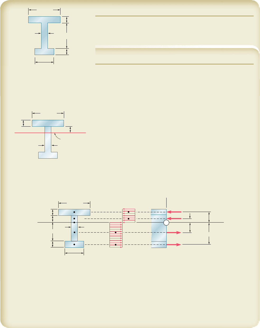
SAMPLE PROBLEM 4.6
Determine the plastic moment M
p
of a beam with the cross section shown
when the beam is bent about a horizontal axis. Assume that the material is
elastoplastic with a yield strength of 240 MPa.
SOLUTION
Neutral Axis. When the deformation is fully plastic, the neutral axis
divides the cross section into two portions of equal areas. Since the total
area is
A 5 (100)(20) 1 (80)(20) 1 (60)(20) 5 4800 mm
2
the area located above the neutral axis must be 2400 mm
2
. We write
(20)(100) 1 20y 5 2400 y 5 20 mm
Note that the neutral axis does not pass through the centroid of the cross
section.
Plastic Moment. The resultant R
i
of the elementary forces exerted on
the partial area A
i
is equal to
R
i
5 A
i
s
Y
and passes through the centroid of that area. We have
R
1
5 A
1
s
Y
5
31
0.100 m
21
0.020 m
24
240 MPa 5 480 kN
R
2
5 A
2
s
Y
5
31
0.020 m
21
0.020 m
24
240 MPa 5 96 kN
R
3
5 A
3
s
Y
5
31
0.020 m
21
0.060 m
24
240 MPa 5 288 kN
R
4
5 A
4
s
Y
5
31
0.060 m
21
0.020 m
24
240 MPa 5 288 kN
The plastic moment M
p
is obtained by summing the moments of the forces
about the z axis.
M
p
5
1
0.030 m
2
R
1
1
1
0.010 m
2
R
2
1
1
0.030 m
2
R
3
1
1
0.070 m
2
R
4
5
1
0.030 m
21
480 kN
2
1
1
0.010 m
21
96 kN
2
1
1
0.030 m
21
288 kN
2
1
1
0.070 m
21
288 kN
2
5 44
.
16
k
N ? m M
p
5 44.2 kN ? m
◀
Note: Since the cross section is not symmetric about the z axis, the sum
of the moments of R
1
and R
2
is not equal to the sum of the moments of
R
3
and R
4
.
60 mm
100 mm
20 mm
80 mm
20 mm
20 mm
100 mm
20 mm
Neutral axis
20 mm
y
100 mm
60 mm
z
A
3
A
4
A
2
A
1
20 mm
20 mm
20 mm
60 mm
20 mm
30 mm
30 mm
70 mm
10 mm
R
1
R
2
R
3
R
4
x
y
240 MPa
Y
z
bee80288_ch04_220-313.indd Page 264 10/27/10 5:46:19 PM user-f499bee80288_ch04_220-313.indd Page 264 10/27/10 5:46:19 PM user-f499 /Users/user-f499/Desktop/Temp Work/Don't Delete Job/MHDQ251:Beer:201/ch04/Users/user-f499/Desktop/Temp Work/Don't Delete Job/MHDQ251:Beer:201/ch04
Apago PDF Enhancer
265
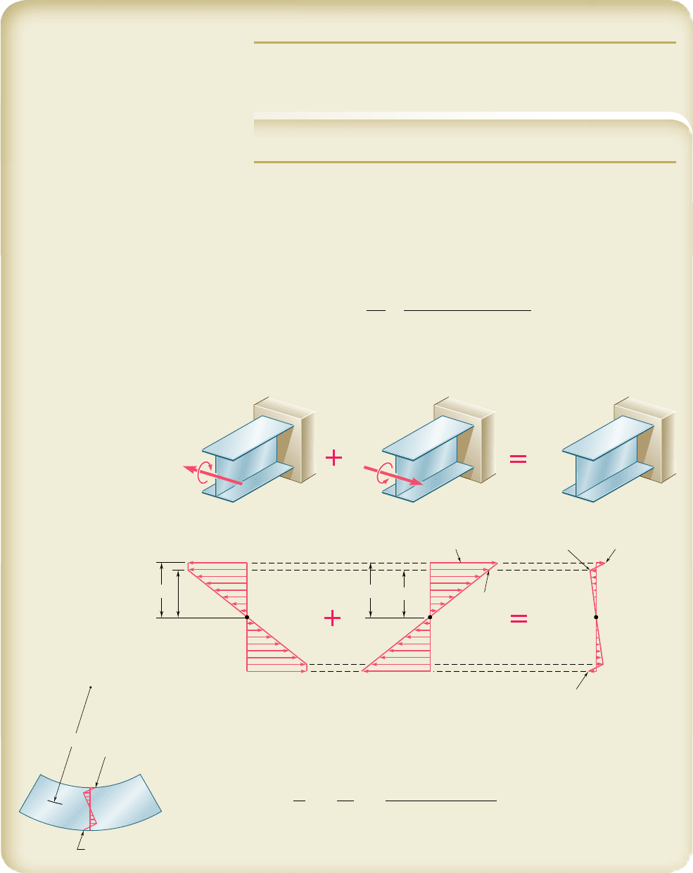
SAMPLE PROBLEM 4.7
For the beam of Sample Prob. 4.5, determine the residual stresses and the
permanent radius of curvature after the 10,230-kip ? in. couple M has been
removed.
SOLUTION
Loading. In Sample Prob. 4.5 a couple of moment M 5 10,230 kip ? in.
was applied and the stresses shown in Fig. 1 were obtained.
Elastic Unloading. The beam is unloaded by the application of a
couple of moment M 5 210,230 kip ? in. (which is equal and opposite to
the couple originally applied). During this unloading, the action of the beam
is fully elastic; recalling from Sample Prob. 4.5 that I 5 1524 in
4
, we com-
pute the maximum stress
s¿
m
5
Mc
I
5
1
10,230 kip ? in.
21
8 in.
2
1
5
24 in
4
5 53.70 ksi
The stresses caused by the unloading are shown in Fig. 2.
Residual Stresses. We superpose the stresses due to the loading (Fig. 1) and
to the unloading (Fig. 2) and obtain the residual stresses in the beam (Fig. 3).
Permanent Radius of Curvature. At y 5 7 in. the residual stress is
s 5 23.01 ksi. Since no plastic deformation occurred at this point, Hooke’s
law can be used and we have P
x
5 syE. Recalling Eq. (4.8), we write
r 52
y
P
x
52
y
E
s
52
17 in.2129 3 10
6
psi2
23.01 ksi
5167,400 in.
r 5 5620 ft
◀
We note that the residual stress is tensile on the upper face of the beam and
compressive on the lower face, even though the beam is concave upward.
10,230 kip · in.
M 10,230 kip · in.
50 ksi
Y
53.70 ksi 3.01 ksi
3.70 ksi
3.70 ksi
3.01 ksi
'
m
46.99 ksi
8 in.
7 in.
8 in.
7 in.
(1) (2) (3)
3.70 ksi (tension)
3.70 ksi (compression)
bee80288_ch04_220-313.indd Page 265 11/11/10 3:03:16 PM user-f499bee80288_ch04_220-313.indd Page 265 11/11/10 3:03:16 PM user-f499 /Users/user-f499/Desktop/Temp Work/Don't Delete Job/MHDQ251:Beer:201/ch04/Users/user-f499/Desktop/Temp Work/Don't Delete Job/MHDQ251:Beer:201/ch04
Apago PDF Enhancer
PROBLEMS
266
4.67 The prismatic bar shown is made of a steel that is assumed to be
elastoplastic with s
Y
5 300 MPa and is subjected to a couple M
parallel to the x axis. Determine the moment M of the couple for
which (a) yield first occurs, (b) the elastic core of the bar is 4 mm
thick.
4.68 Solve Prob. 4.67, assuming that the couple M is parallel to the
z axis.
4.69 The prismatic bar shown, made of a steel that is assumed to be
elastoplastic with E 5 29 3 10
6
psi and s
Y
5 36 ksi, is subjected
to a couple of 1350 lb ? in. parallel to the z axis. Determine (a) the
thickness of the elastic core, (b) the radius of curvature of the bar.
z
x
8 mm
12 mm
M
Fig. P4.67
M
y
z
in.
5
8
in.
1
2
Fig. P4.69
4.70 Solve Prob. 4.69, assuming that the 1350-lb ? in. couple is parallel
to the y axis.
4.71 A bar of rectangular cross section shown is made of a steel that is
assumed to be elastoplastic with E 5 200 GPa and s
Y
5 300 MPa.
Determine the bending moment M for which (a) yield first occurs,
(b) the plastic zones at the top and bottom of the bar are 12 mm
thick.
30 mm
40 mm
M
M'
Fig. P4.71 and P4.72
4.72 Bar AB is made of a steel that is assumed to be elastoplastic with
E 5 200 GPa and s
Y
5 240 MPa. Determine the bending moment
M for which the radius of curvature of the bar will be (a) 18 m,
(b) 9 m.
bee80288_ch04_220-313.indd Page 266 10/26/10 4:30:06 PM user-f499bee80288_ch04_220-313.indd Page 266 10/26/10 4:30:06 PM user-f499 /Volumes/201/MHDQ251/bee80288_disk1of1/0073380288/bee80288_pagefiles/Volumes/201/MHDQ251/bee80288_disk1of1/0073380288/bee80288_pagefiles
