Beer F.P., Johnston E.R., DeWolf J.T., Mazurek D.F. Mechanics of Materials
Подождите немного. Документ загружается.

Apago PDF Enhancer
227
however, that this discussion does not rule out the possibility of defor-
mations within the plane of the section (see Sec. 4.5).
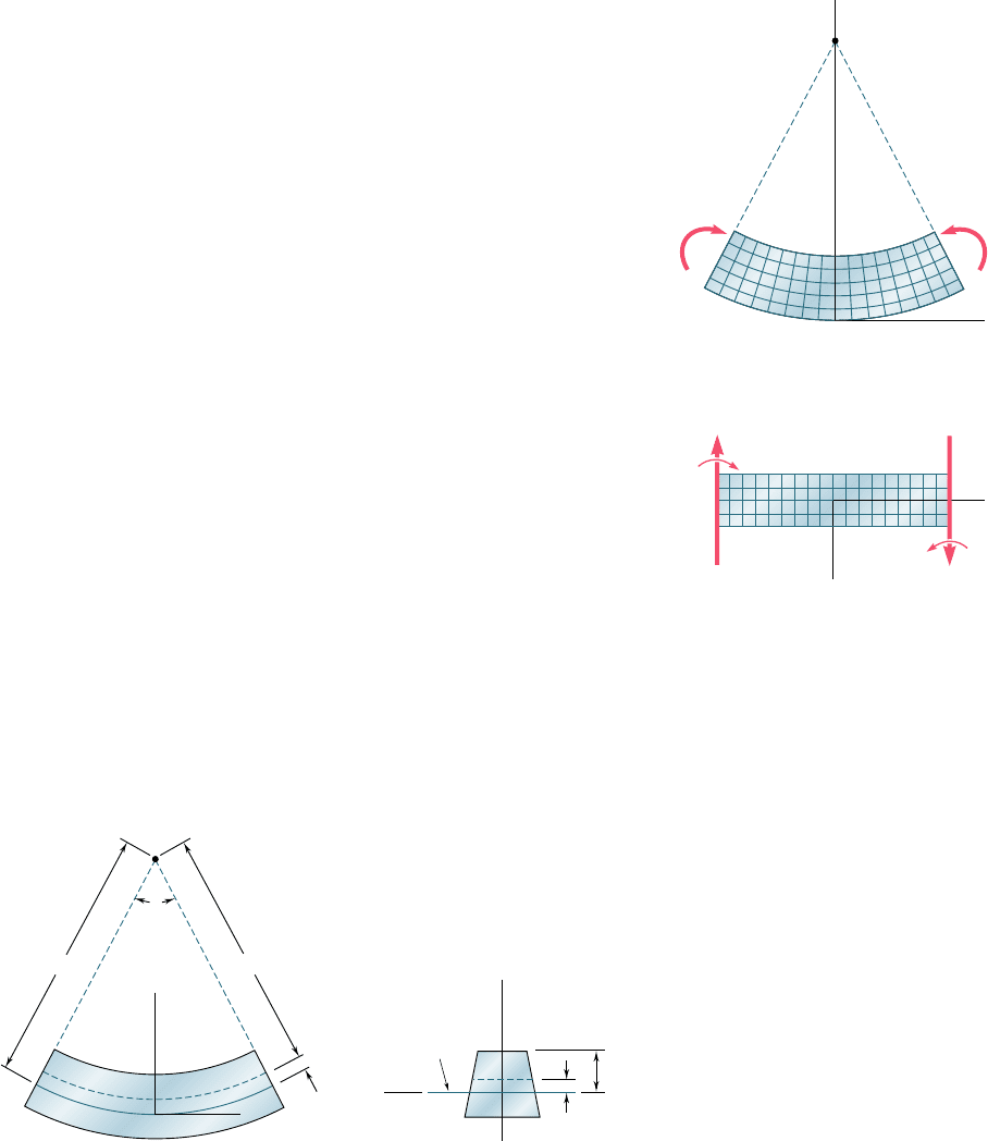
Suppose that the member is divided into a large number of
small cubic elements with faces respectively parallel to the three coor-
dinate planes. The property we have established requires that these
elements be transformed as shown in Fig. 4.9 when the member is
subjected to the couples M and M9. Since all the faces represented
in the two projections of Fig. 4.9 are at 908 to each other, we conclude
that g
xy
5 g
zx
5 0 and, thus, that t
xy
5 t
xz
5 0. Regarding the three
stress components that we have not yet discussed, namely, s
y
, s
z
, and
t
yz
, we note that they must be zero on the surface of the member.
Since, on the other hand, the deformations involved do not require
any interaction between the elements of a given transverse cross sec-
tion, we can assume that these three stress components are equal to
zero throughout the member. This assumption is verified, both from
experimental evidence and from the theory of elasticity, for slender
members undergoing small deformations.† We conclude that the only
nonzero stress component exerted on any of the small cubic elements
considered here is the normal component s
x
. Thus, at any point of a
slender member in pure bending, we have a state of uniaxial stress.
Recalling that, for M . 0, lines AB and A9B9 are observed, respec-
tively, to decrease and increase in length, we note that the strain P
x
and the stress s
x
are negative in the upper portion of the member
(compression) and positive in the lower portion (tension).
It follows from the above that there must exist a surface parallel
to the upper and lower faces of the member, where P
x
and s
x
are zero.
This surface is called the neutral surface. The neutral surface intersects
the plane of symmetry along an arc of circle DE (Fig. 4.10a), and it
intersects a transverse section along a straight line called the neutral
axis of the section (Fig. 4.10b). The origin of coordinates will now be
selected on the neutral surface, rather than on the lower face of the
member as done earlier, so that the distance from any point to the
neutral surface will be measured by its coordinate y.
†Also see Prob. 4.32.
y
y
– y
A
J
D
O
O
C
B
K
E
x
y
y
c
z
A⬘
B⬘
(a) Longitudinal, vertical section
(plane of symmetry)
(b) Transverse section
Neutral
axis
Fig. 4.10 Deformation with respect to neutral axis.
y
A
C
B
x
x
z
M' M
M'
A⬘ B⬘
(a) Longitudinal, vertical section
(plane of symmetry)
(b) Longitudinal, horizontal section
M
Fig. 4.9 Member subject to pure
bending.
4.3 Deformations in a Symmetric
Member in Pure Bending
bee80288_ch04_220-313.indd Page 227 10/26/10 4:24:59 PM user-f499bee80288_ch04_220-313.indd Page 227 10/26/10 4:24:59 PM user-f499 /Volumes/201/MHDQ251/bee80288_disk1of1/0073380288/bee80288_pagefiles/Volumes/201/MHDQ251/bee80288_disk1of1/0073380288/bee80288_pagefiles

Apago PDF Enhancer
228
Pure Bending
Denoting by r the radius of arc DE (Fig. 4.10a), by u the cen-
tral angle corresponding to DE, and observing that the length of DE
is equal to the length L of the undeformed member, we write
L
5 ru (4.4)
Considering now the arc JK located at a distance y above the neutral
surface, we note that its length L9 is
L9
5 (r 2 y)u (4.5)
Since the original length of arc JK was equal to L, the deformation
of JK is
d
5 L9 2 L (4.6)
or, if we substitute from (4.4) and (4.5) into (4.6),
d
5 (r 2 y)u 2 ru 5 2yu (4.7)
The longitudinal strain P
x
in the elements of JK is obtained by divid-
ing d by the original length L of JK. We write
P
x
5
d
L
5
2y
u
ru
or
P
x
52
y
r
(4.8)
The minus sign is due to the fact that we have assumed the bending
moment to be positive and, thus, the beam to be concave upward.
Because of the requirement that transverse sections remain
plane, identical deformations will occur in all planes parallel to the
plane of symmetry. Thus the value of the strain given by Eq. (4.8) is
valid anywhere, and we conclude that the longitudinal normal strain
P
x
varies linearly with the distance y from the neutral surface.
The strain P
x
reaches its maximum absolute value when y itself is
largest. Denoting by c the largest distance from the neutral surface (which
corresponds to either the upper or the lower surface of the member),
and by P
m
the maximum absolute value of the strain, we have
P
m
5
c
r
(4.9)
Solving (4.9) for r and substituting the value obtained into (4.8), we
can also write
P
x
52
y
c
P
m
(4.10)
We conclude our analysis of the deformations of a member in
pure bending by observing that we are still unable to compute the strain
or stress at a given point of the member, since we have not yet located
the neutral surface in the member. In order to locate this surface, we
must first specify the stress-strain relation of the material used.†
†Let us note, however, that if the member possesses both a vertical and a horizontal plane
of symmetry (e.g., a member with a rectangular cross section), and if the stress-strain
curve is the same in tension and compression, the neutral surface will coincide with the
plane of symmetry (cf. Sec. 4.8).
bee80288_ch04_220-313.indd Page 228 11/11/10 3:03:06 PM user-f499bee80288_ch04_220-313.indd Page 228 11/11/10 3:03:06 PM user-f499 /Users/user-f499/Desktop/Temp Work/Don't Delete Job/MHDQ251:Beer:201/ch04/Users/user-f499/Desktop/Temp Work/Don't Delete Job/MHDQ251:Beer:201/ch04
Apago PDF Enhancer
229
4.4 STRESSES AND DEFORMATIONS IN THE
ELASTIC RANGE
We now consider the case when the bending moment M is such that
the normal stresses in the member remain below the yield strength s
Y
.
This means that, for all practical purposes, the stresses in the member
will remain below the proportional limit and the elastic limit as well.
There will be no permanent deformation, and Hooke’s law for uniaxial
stress applies. Assuming the material to be homogeneous, and denoting
by E its modulus of elasticity, we have in the longitudinal x direction
s
x
5 EP
x
(4.11)
Recalling Eq. (4.10), and multiplying both members of that
equation by E, we write
EP
x
52
y
c
1EP
m
2
or, using (4.11),
s
x
52
y
c
s
m
(4.12)
where s
m
denotes the maximum absolute value of the stress. This
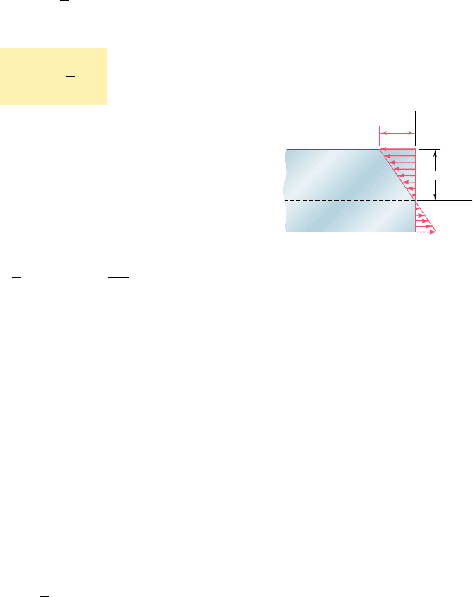
result shows that, in the elastic range, the normal stress varies lin-
early with the distance from the neutral surface (Fig. 4.11).
It should be noted that, at this point, we do not know the loca-
tion of the neutral surface, nor the maximum value s
m
of the stress.
Both can be found if we recall the relations (4.1) and (4.3) which
were obtained earlier from statics. Substituting first for s
x
from (4.12)
into (4.1), we write
#
s
x
dA 5
#
a2
y
c
s
m
b dA 52
s
m
c
#
y dA 5 0
from which it follows that
#
y dA 5 0
(4.13)
This equation shows that the first moment of the cross section about
its neutral axis must be zero.† In other words, for a member subjected
to pure bending, and as long as the stresses remain in the elastic
range, the neutral axis passes through the centroid of the section.
We now recall Eq. (4.3), which was derived in Sec. 4.2 with
respect to an arbitrary horizontal z axis,
#
12ys
x
dA25 M
(4.3)
Specifying that the z axis should coincide with the neutral axis of the
cross section, we substitute for s
x
from (4.12) into (4.3) and write
#
12y2 a2
y
c
s
m
b
dA 5 M
4.4 Stresses and Deformations in the
Elastic Range
†See Appendix A for a discussion of the moments of areas.
y
c
m
x
Neutral surface
Fig. 4.11 Bending stresses.
bee80288_ch04_220-313.indd Page 229 11/11/10 3:03:07 PM user-f499bee80288_ch04_220-313.indd Page 229 11/11/10 3:03:07 PM user-f499 /Users/user-f499/Desktop/Temp Work/Don't Delete Job/MHDQ251:Beer:201/ch04/Users/user-f499/Desktop/Temp Work/Don't Delete Job/MHDQ251:Beer:201/ch04

Apago PDF Enhancer
230
Pure Bending
or
s
m
c
#
y
2
dA 5 M (4.14)
Recalling that in the case of pure bending the neutral axis passes
through the centroid of the cross section, we note that I is the
moment of inertia, or second moment, of the cross section with
respect to a centroidal axis perpendicular to the plane of the couple
M. Solving (4.14) for s
m
, we write therefore†
s
m
5
Mc
I
(4.15)
Substituting for s
m
from (4.15) into (4.12), we obtain the nor-
mal stress s
x
at any distance y from the neutral axis:
s
x
52
M
y
I
(4.16)
Equations (4.15) and (4.16) are called the elastic flexure formulas,
and the normal stress s
x
caused by the bending or “flexing” of the
member is often referred to as the flexural stress. We verify that the
stress is compressive (s
x
, 0) above the neutral axis (y . 0) when
the bending moment M is positive, and tensile (s
x
. 0) when M is
negative.
Returning to Eq. (4.15), we note that the ratio Iyc depends only
upon the geometry of the cross section. This ratio is called the elastic
section modulus and is denoted by S. We have
Elastic section modulus 5 S 5
I
c
(4.17)
Substituting S for Iyc into Eq. (4.15), we write this equation in the
alternative form
s
m
5
M
S
(4.18)
Since the maximum stress s
m
is inversely proportional to the elastic
section modulus S, it is clear that beams should be designed with as
large a value of S as practicable. For example, in the case of a wooden
beam with a rectangular cross section of width b and depth h, we
have
S 5
I
c
5
1
12
bh
3
h
y
2
5
1
6
bh
2
5
1
6
Ah
(4.19)
†We recall that the bending moment was assumed to be positive. If the bending moment
is negative, M should be replaced in Eq. (4.15) by its absolute value |M|.
bee80288_ch04_220-313.indd Page 230 11/11/10 3:03:07 PM user-f499bee80288_ch04_220-313.indd Page 230 11/11/10 3:03:07 PM user-f499 /Users/user-f499/Desktop/Temp Work/Don't Delete Job/MHDQ251:Beer:201/ch04/Users/user-f499/Desktop/Temp Work/Don't Delete Job/MHDQ251:Beer:201/ch04
Apago PDF Enhancer
231
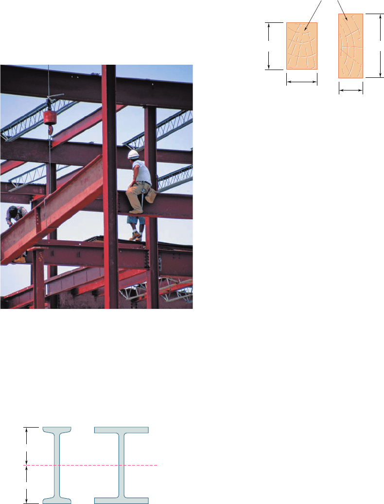
where A is the cross-sectional area of the beam. This shows that, of
two beams with the same cross-sectional area A (Fig. 4.12), the beam
with the larger depth h will have the larger section modulus and,
thus, will be the more effective in resisting bending.†
In the case of structural steel, American standard beams
(S-beams) and wide-flange beams (W-beams), Photo 4.3, are preferred
4.4 Stresses and Deformations in the
Elastic Range
to other shapes because a large portion of their cross section is
located far from the neutral axis (Fig. 4.13). Thus, for a given cross-
sectional area and a given depth, their design provides large values
Photo 4.3 Wide-flange steel beams form the frame
of many buildings.
c
c
(a) S-beam
(b) W-beam
N. A.
Fig. 4.13 Steel beam cross sections.
†However, large values of the ratio hyb could result in lateral instability of the beam.
h
⫽ 6 in.
h ⫽ 8 in.
b ⫽ 4 in.
b ⫽ 3 in.
A ⫽ 24 in
2
Fig. 4.12 Wood beam cross sections.
bee80288_ch04_220-313.indd Page 231 10/28/10 9:25:20 PM user-f499bee80288_ch04_220-313.indd Page 231 10/28/10 9:25:20 PM user-f499 /Volumes/201/MHDQ251/bee80288_disk1of1/0073380288/bee80288_pagefiles/Volumes/201/MHDQ251/bee80288_disk1of1/0073380288/bee80288_pagefiles
Apago PDF Enhancer
232
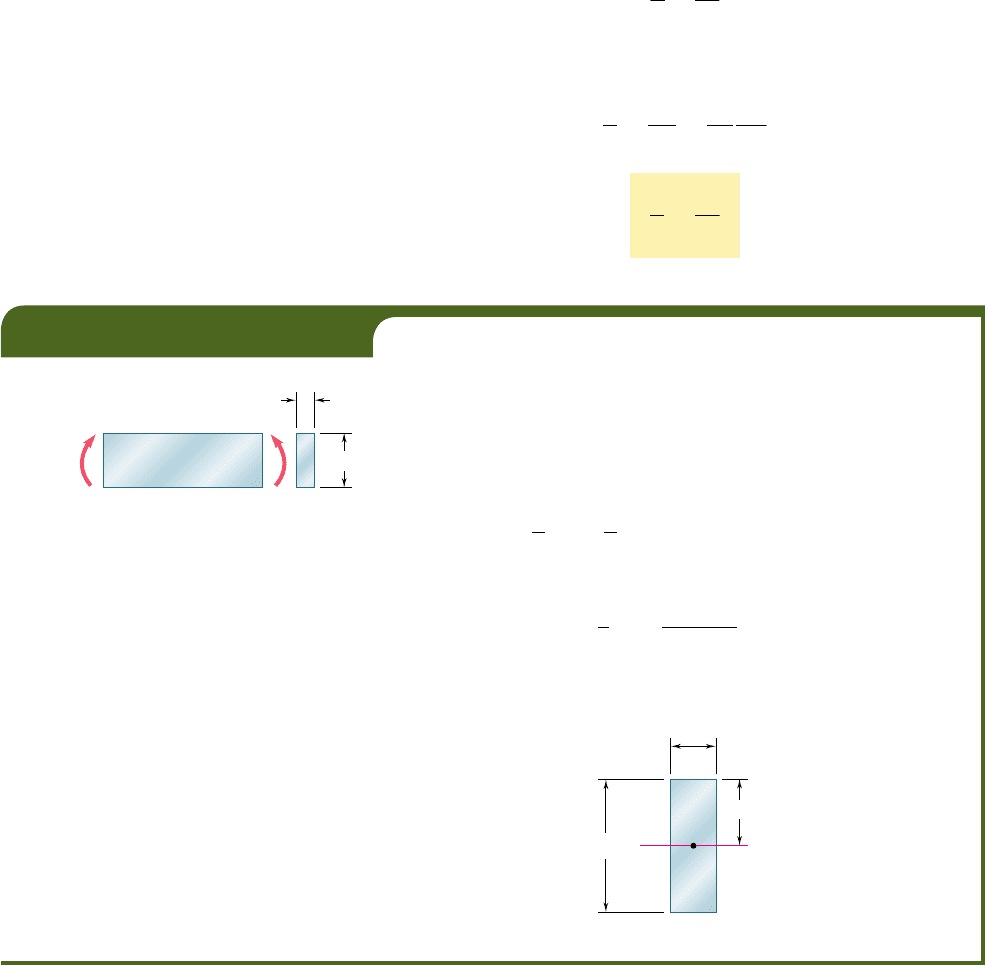
A steel bar of 0.8 3 2.5-in. rectangular cross section is subjected to two
equal and opposite couples acting in the vertical plane of symmetry of
the bar (Fig. 4.14). Determine the value of the bending moment M that
causes the bar to yield. Assume s
Y
5 36 ksi.
Since the neutral axis must pass through the centroid C of the cross
section, we have c 5 1.25 in. (Fig. 4.15). On the other hand, the centroi-
dal moment of inertia of the rectangular cross section is
I 5
1
12
bh
3
5
1
12
10.8 in.212.5 in.2
3
5 1.042 in
4
Solving Eq. (4.15) for M, and substituting the above data, we have
M 5
I
c
s
m
5
1.042 in
4
1
.
25 in
.
136 ksi2
M 5 30
k
ip ? in.
EXAMPLE 4.01
M' M
0.8 in.
2.5 in.
Fig. 4.14
1.25 in.
0.8 in.
N. A.
C
2.5 in.
Fig. 4.15
of I and, consequently, of S. Values of the elastic section modulus of
commonly manufactured beams can be obtained from tables listing
the various geometric properties of such beams. To determine the
maximum stress s
m
in a given section of a standard beam, the engi-
neer needs only to read the value of the elastic section modulus S
in a table, and divide the bending moment M in the section by S.
The deformation of the member caused by the bending moment
M is measured by the curvature of the neutral surface. The curvature
is defined as the reciprocal of the radius of curvature r, and can be
obtained by solving Eq. (4.9) for 1yr:
1
r
5
P
m
c
(4.20)
But, in the elastic range, we have P
m
5 s
m
yE. Substituting for P
m
into (4.20), and recalling (4.15), we write
1
r
5
s
m
Ec
5
1
Ec
Mc
I
or
1
r
5
M
EI
(4.21)
bee80288_ch04_220-313.indd Page 232 10/27/10 5:46:11 PM user-f499bee80288_ch04_220-313.indd Page 232 10/27/10 5:46:11 PM user-f499 /Users/user-f499/Desktop/Temp Work/Don't Delete Job/MHDQ251:Beer:201/ch04/Users/user-f499/Desktop/Temp Work/Don't Delete Job/MHDQ251:Beer:201/ch04
Apago PDF Enhancer
4.5 DEFORMATIONS IN A TRANSVERSE
CROSS SECTION
When we proved in Sec. 4.3 that the transverse cross section of a
member in pure bending remains plane, we did not rule out the
possibility of deformations within the plane of the section. That such
deformations will exist is evident, if we recall from Sec. 2.11 that
elements in a state of uniaxial stress, s
x
? 0, s
y
5 s
z
5 0, are
deformed in the transverse y and z directions, as well as in the axial
x direction. The normal strains P
y
and P
z
depend upon Poisson’s ratio
n for the material used and are expressed as
P
y
5 2nP
x
P
z
5 2nP
x
or, recalling Eq. (4.8),
P
y
5
n
y
r
P
z
5
n
y
r
(4.22)
r 12 mm
Fig. 4.16
N. A.
c
y
C
Fig. 4.17
EXAMPLE 4.02
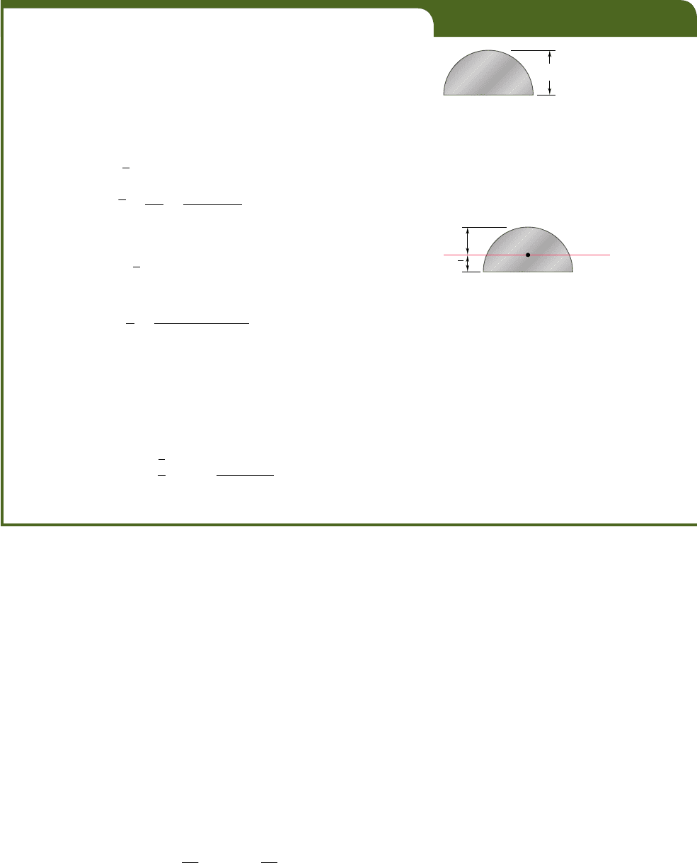
An aluminum rod with a semicircular cross section of radius r 5 12 mm
(Fig. 4.16) is bent into the shape of a circular arc of mean radius r 5 2.5 m.
Knowing that the flat face of the rod is turned toward the center of curvature
of the arc, determine the maximum tensile and compressive stress in the
rod. Use E 5 70 GPa.
We could use Eq. (4.21) to determine the bending moment M cor-
responding to the given radius of curvature r, and then Eq. (4.15) to
determine s
m
. However, it is simpler to use Eq. (4.9) to determine P
m
,
and Hooke’s law to obtain s
m
.
The ordinate
y
of the centroid C of the semicircular cross section is
y
5
4r
3p
5
4112 mm
2
3p
5 5.093 mm
The neutral axis passes through C (Fig. 4.17) and the distance c to the
point of the cross section farthest away from the neutral axis is
c
5 r 2 y 5 12 mm 2 5.093 mm 5 6.907 mm
Using Eq. (4.9), we write
P
m
5
c
r
5
6.907 3 10
23
m
2.5 m
5 2.763 3 10
23
and, applying Hooke’s law,
s
m
5 EP
m
5 170 3 10
9
Pa212.763 3 10
23
25 193.4 MPa
Since this side of the rod faces away from the center of curvature, the
stress obtained is a tensile stress. The maximum compressive stress occurs
on the flat side of the rod. Using the fact that the stress is proportional
to the distance from the neutral axis, we write
s
comp
52
y
c
s
m
52
5.093 mm
6
.
907 mm
1193.4 MPa2
52
142.6
MP
a
233
bee80288_ch04_220-313.indd Page 233 11/11/10 3:03:08 PM user-f499bee80288_ch04_220-313.indd Page 233 11/11/10 3:03:08 PM user-f499 /Users/user-f499/Desktop/Temp Work/Don't Delete Job/MHDQ251:Beer:201/ch04/Users/user-f499/Desktop/Temp Work/Don't Delete Job/MHDQ251:Beer:201/ch04
Apago PDF Enhancer
234
Pure Bending
The relations we have obtained show that the elements
located above the neutral surface (y . 0) will expand in both the
y and z directions, while the elements located below the neutral
surface (y , 0) will contract. In the case of a member of rectan-
gular cross section, the expansion and contraction of the various
elements in the vertical direction will compensate, and no change
in the vertical dimension of the cross section will be observed. As
far as the deformations in the horizontal transverse z direction are
concerned, however, the expansion of the elements located above
the neutral surface and the corresponding contraction of the ele-
ments located below that surface will result in the various hori-
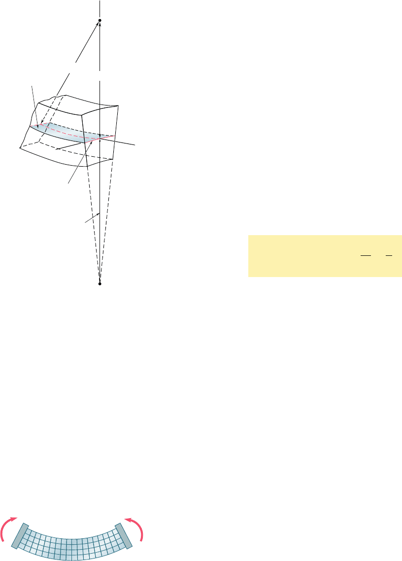
zontal lines in the section being bent into arcs of circle (Fig. 4.18).
The situation observed here is similar to that observed earlier in
a longitudinal cross section. Comparing the second of Eqs. (4.22)
with Eq. (4.8), we conclude that the neutral axis of the transverse
section will be bent into a circle of radius r9 5 ryn. The center
C9 of this circle is located below the neutral surface (assuming M
. 0), i.e., on the side opposite to the center of curvature C of the
member. The reciprocal of the radius of curvature r9 represents
the curvature of the transverse cross section and is called the anti-
clastic curvature. We have
Anticlastic curvature 5
1
r
¿
5
n
r
(4.23)
In our discussion of the deformations of a symmetric member
in pure bending, in this section and in the preceding ones, we have
ignored the manner in which the couples M and M9 were actually
applied to the member. If all transverse sections of the member,
from one end to the other, are to remain plane and free of shearing
stresses, we must make sure that the couples are applied in such a
way that the ends of the member themselves remain plane and free
of shearing stresses. This can be accomplished by applying the cou-
ples M and M9 to the member through the use of rigid and smooth
plates (Fig. 4.19). The elementary forces exerted by the plates on
the member will be normal to the end sections, and these sections,
while remaining plane, will be free to deform as described earlier in
this section.
We should note that these loading conditions cannot be actually
realized, since they require each plate to exert tensile forces on the
corresponding end section below its neutral axis, while allowing the
section to freely deform in its own plane. The fact that the rigid-end-
plates model of Fig. 4.19 cannot be physically realized, however, does
not detract from its importance, which is to allow us to visualize the
loading conditions corresponding to the relations derived in the pre-
ceding sections. Actual loading conditions may differ appreciably
from this idealized model. By virtue of Saint-Venant’s principle, how-
ever, the relations obtained can be used to compute stresses in engi-
neering situations, as long as the section considered is not too close
to the points where the couples are applied.
Neutral
surface
x
z
Neutral axis of
transverse section
C⬘
C
y
⬘ /
Fig. 4.18 Deformation of transverse
cross section.
M
M'
Fig. 4.19 Deformation of longitudinal
segment.
bee80288_ch04_220-313.indd Page 234 10/27/10 5:46:13 PM user-f499bee80288_ch04_220-313.indd Page 234 10/27/10 5:46:13 PM user-f499 /Users/user-f499/Desktop/Temp Work/Don't Delete Job/MHDQ251:Beer:201/ch04/Users/user-f499/Desktop/Temp Work/Don't Delete Job/MHDQ251:Beer:201/ch04
Apago PDF Enhancer
235
SAMPLE PROBLEM 4.1
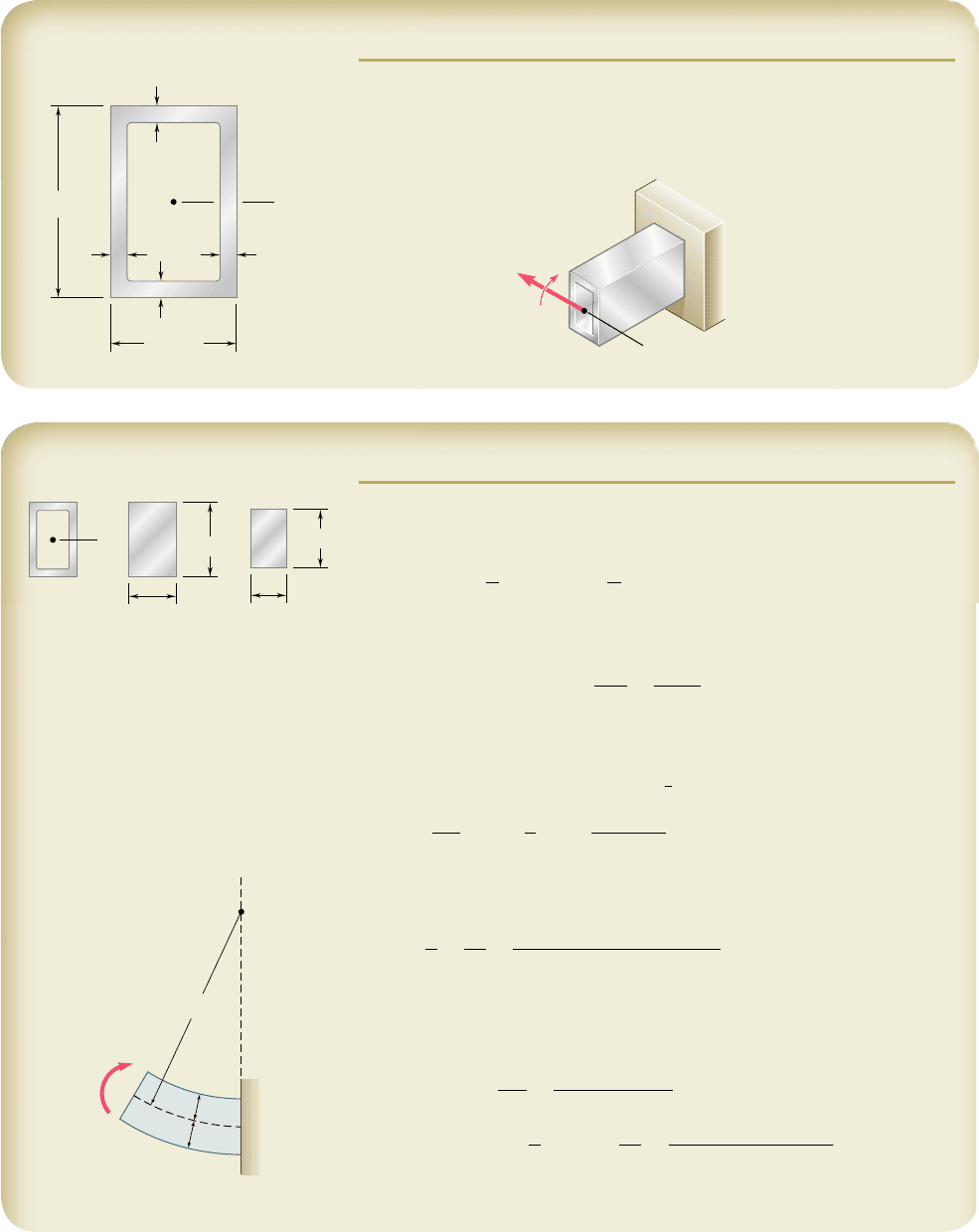
The rectangular tube shown is extruded from an aluminum alloy for which
s
Y
5 40 ksi, s
U
5 60 ksi, and E 5 10.6 3 10
6
psi. Neglecting the effect
of fillets, determine (a) the bending moment M for which the factor of
safety will be 3.00, (b) the corresponding radius of curvature of the tube.
5 in.
C
t
t
t
t 0.25 in.
3.25 in.
t
x
M
x
SOLUTION
Moment of Inertia. Considering the cross-sectional area of the tube
as the difference between the two rectangles shown and recalling the for-
mula for the centroidal moment of inertia of a rectangle, we write
I 5
1
1
2
1
3.25
21
5
2
3
2
1
1
2
1
2.75
21
4.5
2
3
I 5 12.97 in
4
Allowable Stress. For a factor of safety of 3.00 and an ultimate stress
of 60 ksi, we have
s
all
5
s
U
F.S.
5
60
k
si
3.00
5 20 ksi
Since s
all
, s
Y
, the tube remains in the elastic range and we can apply the
results of Sec. 4.4.
a. Bending Moment. With
c
5
1
2
1
5 in.
2
5 2.5 in., we write
s
all
5
Mc
I
M 5
I
c
s
all
5
12.97 in
4
2
.5
i
n.
120 ksi2
M 5 103.8
k
ip ? in.
◀
b. Radius of Curvature. Recalling that E 5 10.6 3 10
6
psi, we substi-
tute this value and the values obtained for I and M into Eq. (4.21) and find
1
r
5
M
EI
5
103.8 3 10
3
lb ? in.
110.6 3 10
6
psi2112.97 in
4
2
5 0.755 3 10
23
in
21
r 5 1325 in. r 5 110.4 ft
◀
Alternative Solution. Since we know that the maximum stress is s
all
5 20 ksi, we can determine the maximum strain P
m
and then use Eq. (4.9),
P
m
5
s
all
E
5
20 ksi
10.6 3 10
6
psi
5 1.887 3 10
23
in./in.
P
m
5
c
r
r 5
c
P
m
5
2.5 in.
1.887 3 10
23
in./in.
r 5 1325 in. r 5 110.4 ft
◀
C
3.25 in.
5 in.
4.5 in.
x
2.75 in.
=
−
O
M
c
c
bee80288_ch04_220-313.indd Page 235 11/11/10 3:03:09 PM user-f499bee80288_ch04_220-313.indd Page 235 11/11/10 3:03:09 PM user-f499 /Users/user-f499/Desktop/Temp Work/Don't Delete Job/MHDQ251:Beer:201/ch04/Users/user-f499/Desktop/Temp Work/Don't Delete Job/MHDQ251:Beer:201/ch04
Apago PDF Enhancer
236
SAMPLE PROBLEM 4.2
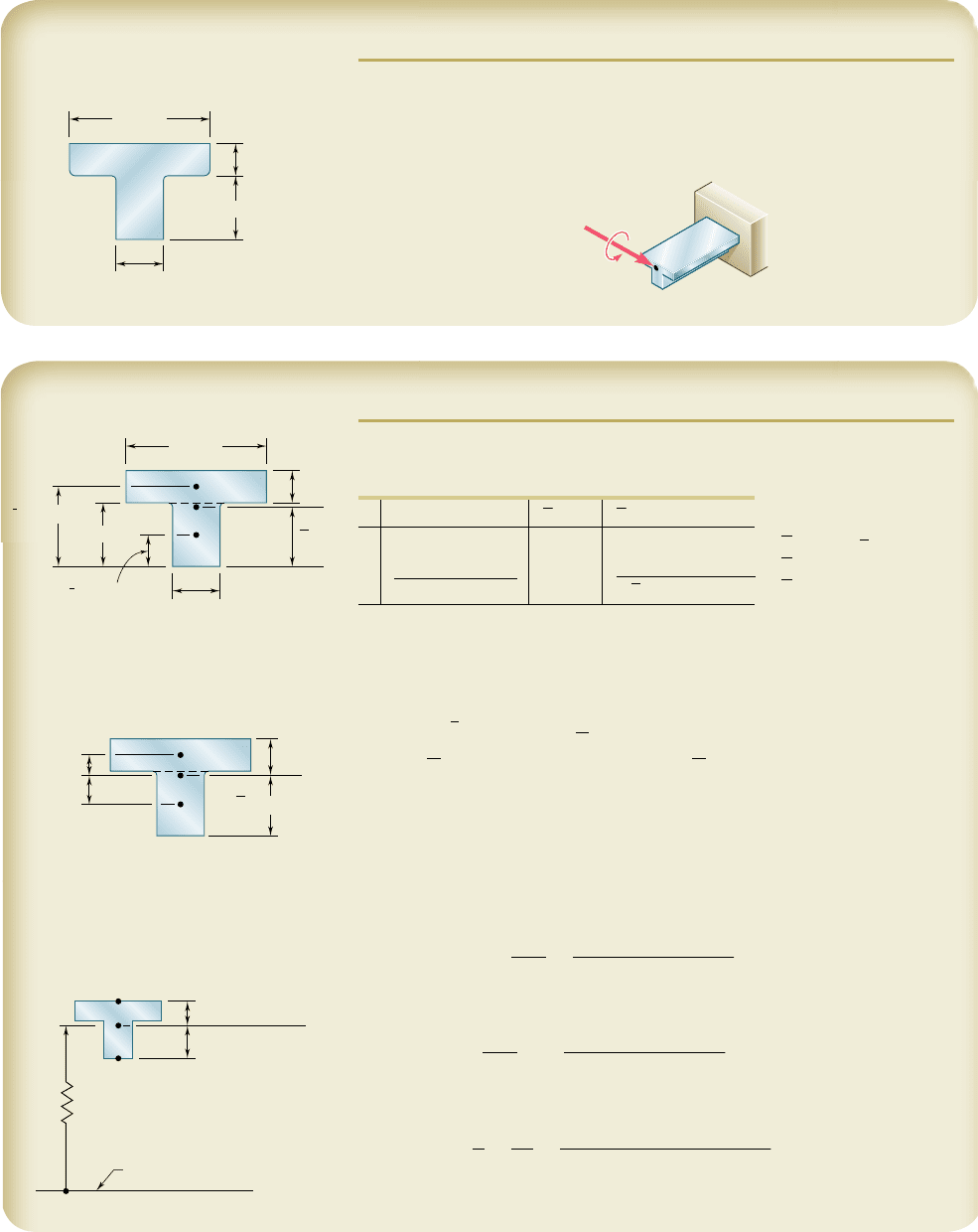
A cast-iron machine part is acted upon by the 3 kN ? m couple shown.
Knowing that E 5 165 GPa and neglecting the effect of fillets, determine
(a) the maximum tensile and compressive stresses in the casting, (b) the
radius of curvature of the casting.
90 mm
30 mm
20 mm
40 mm
M 3 kN · m
SOLUTION
Centroid. We divide the T-shaped cross section into the two rectan-
gles shown and write
Area, mm
2
y
, mm
y
A, mm
3
1
1
20
21
90
2
5 1800 50
90
3
10
3
Y©A 5 ©yA
2
1
40
21
30
2
5 1200 20 2
4
3
10
3
Y
1
3000
2
5 114 3 10
6
©A
5
3000
©yA 5 114 3 10
3
Y
5
38
mm
Centroidal Moment of Inertia. The parallel-axis theorem is used to
determine the moment of inertia of each rectangle with respect to the axis
x9 that passes through the centroid of the composite section. Adding the
moments of inertia of the rectangles, we write
I
x¿
5 ©
1
I 1 Ad
2
2
5 ©
1
1
1
2
bh
3
1 Ad
2
2
5
1
1
2
1
90
21
20
2
3
1
1
90 3 20
21
12
2
2
1
1
1
2
1
30
21
40
2
3
1
1
30 3 40
21
18
2
2
5 868 3 10
3
mm
4
I 5 868 3 10
2
9
m
4
a. Maximum Tensile Stress. Since the applied couple bends the cast-
ing downward, the center of curvature is located below the cross section.
The maximum tensile stress occurs at point A, which is farthest from the
center of curvature.
s
A
5
Mc
A
I
5
1
3 kN ? m
21
0.022 m
2
868 3 10
29
m
4
s
A
5176.0 MPab
Maximum Compressive Stress. This occurs at point B; we have
s
B
52
Mc
B
I
52
1
3 kN ? m
21
0.038 m
2
868 3 10
29
m
4
s
B
52131.3 MPab
b. Radius of Curvature. From Eq. (4.21), we have
1
r
5
M
EI
5
3
k
N ? m
1
165 GPa
21
868 3 10
29
m
4
2
5 20
.
95 3 10
2
3
m
2
1
r 5 47.7 mb
90 mm
y
1
50 mm
y
2
20 mm
40 mm
2
1
30 mm
20 mm
x'
x
C
12 mm
18 mm
22 mm
38 mm
x'
2
1
C
c
A
0.022 m
A
B
C
Center of curvature
c
B
0.038 m
x'
bee80288_ch04_220-313.indd Page 236 11/11/10 3:03:10 PM user-f499bee80288_ch04_220-313.indd Page 236 11/11/10 3:03:10 PM user-f499 /Users/user-f499/Desktop/Temp Work/Don't Delete Job/MHDQ251:Beer:201/ch04/Users/user-f499/Desktop/Temp Work/Don't Delete Job/MHDQ251:Beer:201/ch04
