Beer F.P., Johnston E.R., DeWolf J.T., Mazurek D.F. Mechanics of Materials
Подождите немного. Документ загружается.

Apago PDF Enhancer
247
EXAMPLE 4.04
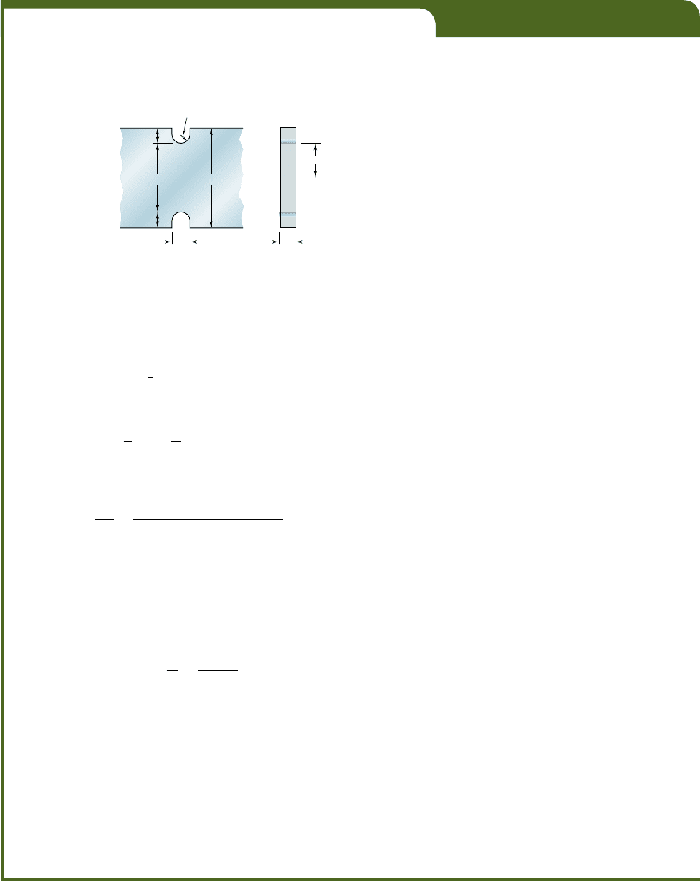
Grooves 10 mm deep are to be cut in a steel bar which is 60 mm wide
and 9 mm thick (Fig. 4.29). Determine the smallest allowable width of
the grooves if the stress in the bar is not to exceed 150 MPa when the
bending moment is equal to 180 N ? m.
d
10 mm
10 mm
D 60 mm
b 9 mm
2r
r
(a)(b)
c
Fig. 4.29
We note from Fig. 4.29a that
d
5 60 mm 2 2
1
10 mm
2
5 40 mm
c 5
1
2
d 5 20 mm b 5 9 mm
The moment of inertia of the critical cross section about its neutral
axis is
I 5
1
12
bd
3
5
1
12
1
9 3 10
23
m
21
40 3 10
23
m
2
3
5 48 3 10
2
9
m
4
The value of the stress McyI is thus
M
c
I
5
1180 N ? m2120 3 10
2
3
m2
48 3 10
29
m
4
5 75 MPa
Substituting this value for McyI into Eq. (4.29) and making s
m
5 150 MPa,
we write
150 MPa 5 K(75 MPa)
K 5 2
We have, on the other hand,
D
d
5
60
mm
40 mm
5 1.5
Using the curve of Fig. 4.32 corresponding to Dyd 5 1.5, we find that
the value K 5 2 corresponds to a value of ryd equal to 0.13. We have,
therefore,
r
d
5 0.13
r 5 0.13d 5 0.13(40 mm) 5 5.2 mm
The smallest allowable width of the grooves is thus
2r 5 2(5.2 mm) 5 10.4 mm
bee80288_ch04_220-313.indd Page 247 10/26/10 4:28:02 PM user-f499bee80288_ch04_220-313.indd Page 247 10/26/10 4:28:02 PM user-f499 /Volumes/201/MHDQ251/bee80288_disk1of1/0073380288/bee80288_pagefiles/Volumes/201/MHDQ251/bee80288_disk1of1/0073380288/bee80288_pagefiles
Apago PDF Enhancer
SAMPLE PROBLEM 4.3
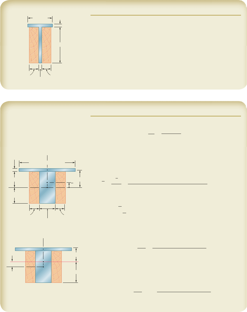
Two steel plates have been welded together to form a beam in the shape of
a T that has been strengthened by securely bolting to it the two oak timbers
shown. The modulus of elasticity is 12.5 GPa for the wood and 200 GPa for
the steel. Knowing that a bending moment M 5 50 kN ? m is applied to the
composite beam, determine (a) the maximum stress in the wood, (b) the
stress in the steel along the top edge.
200 mm
20 mm
300 mm
20 mm
75 mm75 mm
SOLUTION
Transformed Section. We first compute the ratio
n 5
E
s
E
w
5
200 GP
a
12.5 GPa
5 16
Multiplying the horizontal dimensions of the steel portion of the section by
n 5 16, we obtain a transformed section made entirely of wood.
Neutral Axis. The neutral axis passes through the centroid of the
transformed section. Since the section consists of two rectangles, we have
Y 5
©
yA
©A
5
10.160 m213.2 m 3 0.020 m21
0
3.2 m 3 0.020 m 1 0.470 m 3 0.300 m
5 0.050 m
Centroidal Moment of Inertia. Using the parallel-axis theorem:
I 5
1
1
2
1
0.470
21
0.300
2
3
1
1
0.470 3 0.300
21
0.050
2
2
1
1
1
2
1
3.2
21
0.020
2
3
1
1
3.2 3 0.020
21
0.160 2 0.050
2
2
I
5 2
.19
3
10
23
m
4
a. Maximum Stress in Wood. The wood farthest from the neutral
axis is located along the bottom edge, where c
2
5 0.200 m.
s
w
5
Mc
2
I
5
150 3 10
3
N ? m210.200 m2
2
.
19 3 10
23
m
4
s
w
5 4.57 MPab
b. Stress in Steel. Along the top edge c
1
5 0.120 m. From the trans-
formed section we obtain an equivalent stress in wood, which must be mul-
tiplied by n to obtain the stress in steel.
s
s
5 n
Mc
1
I
5 1162
150 3 10
3
N ? m210.120 m2
2
.
19 3 10
23
m
4
s
s
5 43.8 MPab
16(0.200 m) 3.2 m
0.150 m
0.150 m
0.020 m
y
Y
C
O
0.160 m
16(0.020 m) 0.32 m
0.075 m0.075 m
z
N. A.
0.050 m
y
C
O
c
1
0.120 m
c
2
0.200 m
z
248
bee80288_ch04_220-313.indd Page 248 11/11/10 3:03:12 PM user-f499bee80288_ch04_220-313.indd Page 248 11/11/10 3:03:12 PM user-f499 /Users/user-f499/Desktop/Temp Work/Don't Delete Job/MHDQ251:Beer:201/ch04/Users/user-f499/Desktop/Temp Work/Don't Delete Job/MHDQ251:Beer:201/ch04
Apago PDF Enhancer
249
SOLUTION
Transformed Section. We consider a portion of the slab 12 in. wide, in
which there are two
5
8
-in.-diameter rods having a total cross-sectional area
A
s
5 2 c
p
4
a
5
8
in.b
2
d5 0.614 in
2
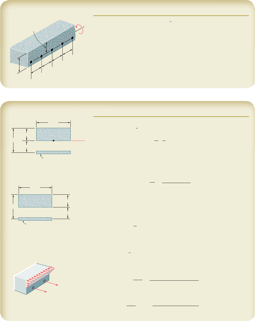
Since concrete acts only in compression, all the tensile forces are carried by
the steel rods, and the transformed section consists of the two areas shown.
One is the portion of concrete in compression (located above the neutral
axis), and the other is the transformed steel area nA
s
. We have
n 5
E
s
E
c
5
29 3 10
6
psi
3.6 3 10
6
psi
5 8.06
n
A
s
5 8.06
1
0.614 in
2
2
5 4.95 in
2
Neutral Axis. The neutral axis of the slab passes through the centroid
of the transformed section. Summing moments of the transformed area
about the neutral axis, we write
12x
a
x
2
b
2 4.9514 2 x25 0x 5 1.450 in.
Moment of Inertia. The centroidal moment of inertia of the trans-
formed area is
I 5
1
3
1
12
21
1.450
2
3
1 4.95
1
4 2 1.450
2
2
5 44.4 in
4
a. Maximum Stress in Concrete. At the top of the slab, we have
c
1
5 1.450 in. and
s
c
5
Mc
1
I
5
140 kip ? in.211.450 in.
2
44.4
i
n
4
s
c
5 1.306 ksib
b. Stress in Steel. For the steel, we have c
2
5 2.55 in., n 5 8.06 and
s
s
5 n
Mc
2
I
5 8.06
140 kip ? in.212.55 in.2
44.4
i
n
4
s
s
5 18.52 ksib
SAMPLE PROBLEM 4.4
A concrete floor slab is reinforced by
5
8
-in.-diameter steel rods placed 1.5 in.
above the lower face of the slab and spaced 6 in. on centers. The modulus
of elasticity is 3.6 3 10
6
psi for the concrete used and 29 3 10
6
psi for the
steel. Knowing that a bending moment of 40 kip ? in. is applied to each 1-ft
width of the slab, determine (a) the maximum stress in the concrete, (b) the
stress in the steel.
6 in.
6 in.
6 in.
6 in.
5.5 in.
4 in.
nA
s
4.95 in
2
4 in.
12 in.
N. A.
4 x
x
C
4.95 in
2
4 in.
12 in.
c
2
4 x
2.55 in.
c
1
x
1.450 in.
c
1.306 ksi
s
18.52 ksi
bee80288_ch04_220-313.indd Page 249 10/26/10 4:28:13 PM user-f499bee80288_ch04_220-313.indd Page 249 10/26/10 4:28:13 PM user-f499 /Volumes/201/MHDQ251/bee80288_disk1of1/0073380288/bee80288_pagefiles/Volumes/201/MHDQ251/bee80288_disk1of1/0073380288/bee80288_pagefiles
Apago PDF Enhancer
PROBLEMS
250
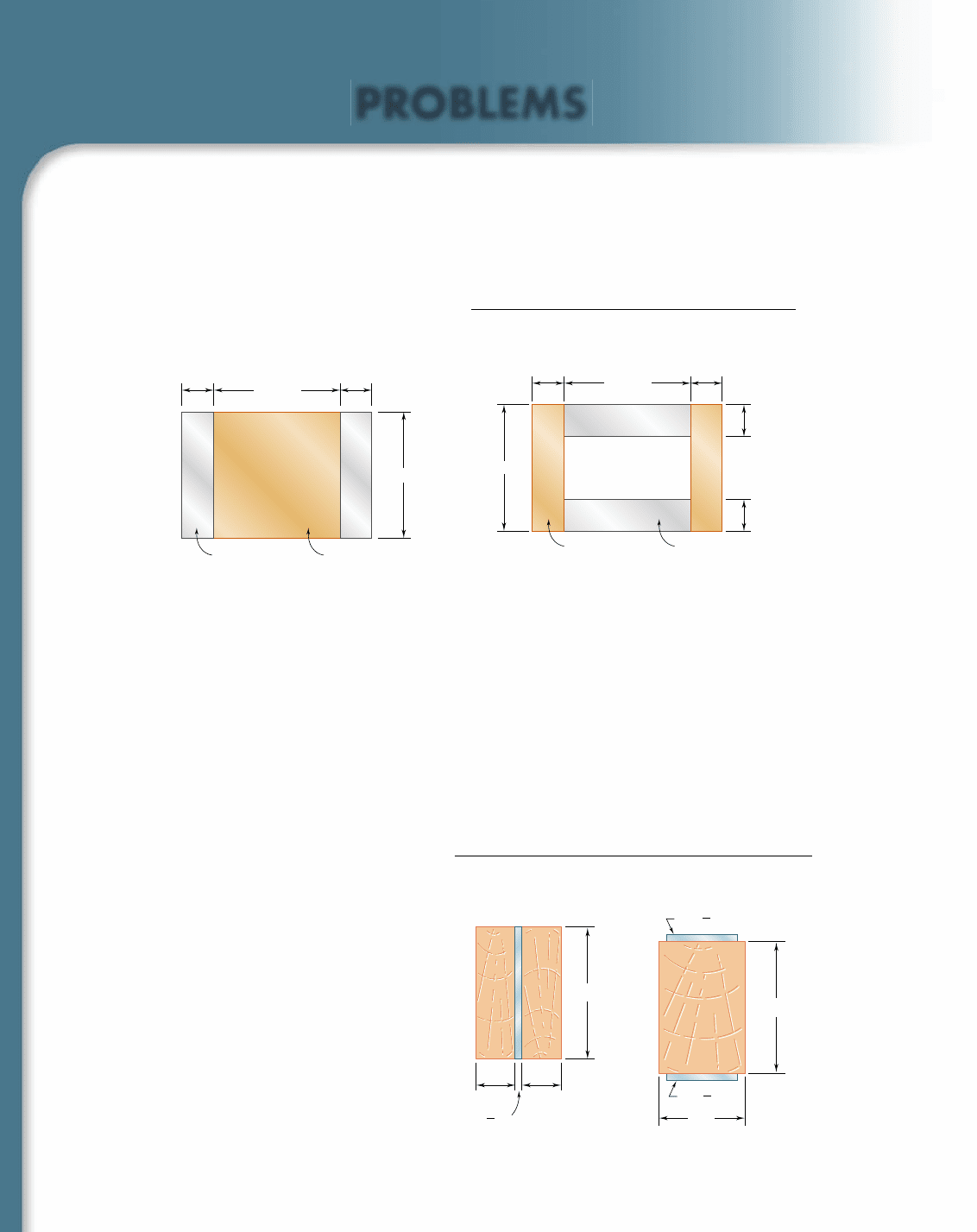
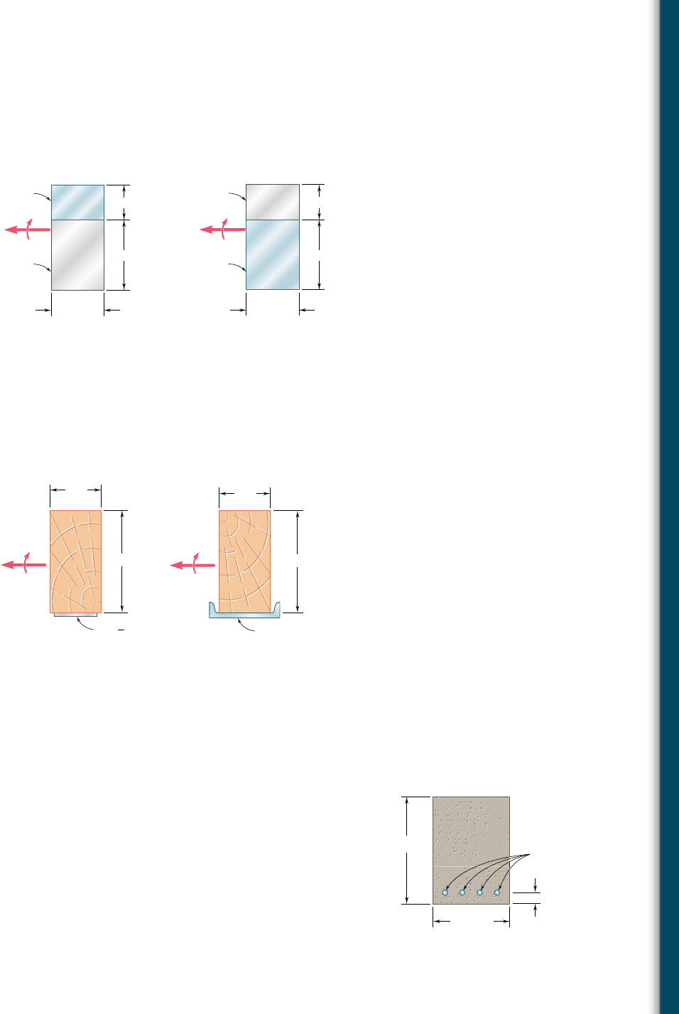
4.33 and 4.34 A bar having the cross section shown has been
formed by securely bonding brass and aluminum stock. Using the
data given below, determine the largest permissible bending
moment when the composite bar is bent about a horizontal axis.
32 mm
32 mm
8 mm 8 mm
8 mm
8 mm
AluminumBrass
Fig. P4.34
Aluminum Brass
Modulus of elasticity 70 GPa 105 GPa
Allowable stress 100 MPa 160 MPa
32 mm
32 mm
8 mm 8 mm
Aluminum Brass
Fig. P4.33
4.35 and 4.36 For the composite bar indicated, determine the larg-
est permissible bending moment when the bar is bent about a
vertical axis.
4.35 Bar of Prob. 4.33.
4.36 Bar of Prob. 4.34.
4.37 and 4.38 Wooden beams and steel plates are securely bolted
together to form the composite member shown. Using the data
given below, determine the largest permissible bending moment
when the member is bent about a horizontal axis.
10 in.
6 in.
in.
1
2
5
in.
1
2
5
Fig. P4.38Fig. P4.37
10 in.
3 in.
in.
3 in.
1
2
Wood Steel
Modulus of elasticity 2 3 10
6
psi 29 3 10
6
psi
Allowable stress 2000 psi 22 ksi
bee80288_ch04_220-313.indd Page 250 10/26/10 4:28:23 PM user-f499bee80288_ch04_220-313.indd Page 250 10/26/10 4:28:23 PM user-f499 /Volumes/201/MHDQ251/bee80288_disk1of1/0073380288/bee80288_pagefiles/Volumes/201/MHDQ251/bee80288_disk1of1/0073380288/bee80288_pagefiles
Apago PDF Enhancer
251
Problems
4.39 and 4.40 A steel bar and an aluminum bar are bonded together
to form the composite beam shown. The modulus of elasticity for
aluminum is 70 GPa and for steel is 200 GPa. Knowing that the
beam is bent about a horizontal axis by a couple of moment M 5
1500 N ? m, determine the maximum stress in (a) the aluminum,
(b) the steel.
M
Steel
Aluminum
20 mm
40 mm
30 mm
Fig. P4.39
M
Aluminum
Steel
20 mm
40 mm
30 mm
Fig. P4.40
4.41 and 4.42 The 6 3 12-in. timber beam has been strengthened
by bolting to it the steel reinforcement shown. The modulus of
elasticity for wood is 1.8 3 10
6
psi and for steel is 29 3 10
6
psi.
Knowing that the beam is bent about a horizontal axis by a couple
of moment M 5 450 kip ? in., determine the maximum stress in
(a) the wood, (b) the steel.
in.5
1
2
6 in.
12 in.
M
Fig. P4.41 Fig. P4.42
6 in.
12 in.
C8 11.5
M
4.43 and 4.44 For the composite beam indicated, determine the
radius of curvature caused by the couple of moment 1500 N ? m.
4.43 Beam of Prob. 4.39.
4.44 Beam of Prob. 4.40.
4.45 and 4.46 For the composite beam indicated, determine the
radius of curvature caused by the couple of moment 450 kip ? in.
4.45 Beam of Prob. 4.41.
4.46 Beam of Prob. 4.42.
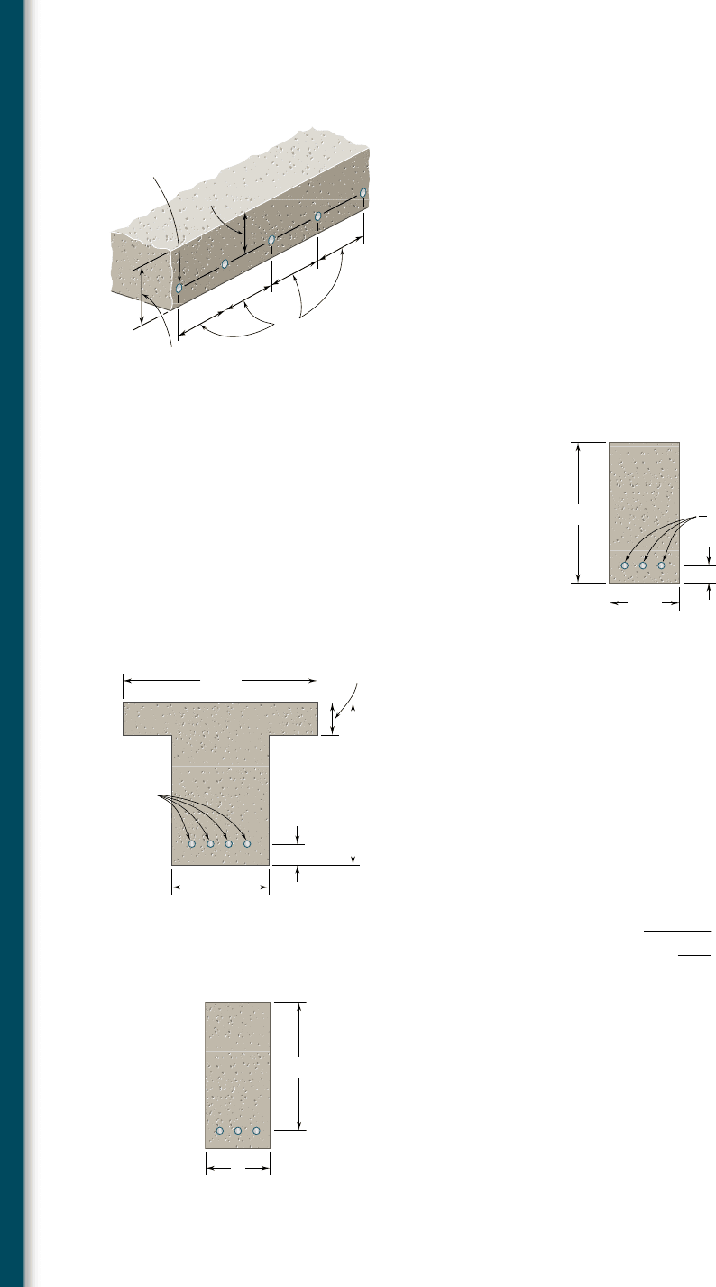
4.47 The reinforced concrete beam shown is subjected to a positive bend-
ing moment of 175 kN ? m. Knowing that the modulus of elasticity
is 25 GPa for the concrete and 200 GPa for the steel, determine
(a) the stress in the steel, (b) the maximum stress in the concrete.
4.48 Solve Prob. 4.47, assuming that the 300-mm width is increased to
350 mm.
300 mm
540 mm
60 mm
25-mm
diamete
r
Fig. P4.47
bee80288_ch04_220-313.indd Page 251 10/26/10 4:28:33 PM user-f499bee80288_ch04_220-313.indd Page 251 10/26/10 4:28:33 PM user-f499 /Volumes/201/MHDQ251/bee80288_disk1of1/0073380288/bee80288_pagefiles/Volumes/201/MHDQ251/bee80288_disk1of1/0073380288/bee80288_pagefiles
Apago PDF Enhancer
252
Pure Bending
4.49 A concrete slab is reinforced by 16-mm-diameter steel rods
placed on 180-mm centers as shown. The modulus of elasticity is
20 GPa for the concrete and 200 GPa for the steel. Using an
allowable stress of 9 MPa for the concrete and 120 MPa for the
steel, determine the largest bending moment in a portion of slab
1 m wide.
4.50 Solve Prob. 4.49, assuming that the spacing of the 16-mm-diameter
rods is increased to 225 mm on centers.
4.51 A concrete beam is reinforced by three steel rods placed as shown.
The modulus of elasticity is 3 3 10
6
psi for the concrete and 29 3
10
6
psi for the steel. Using an allowable stress of 1350 psi for the
concrete and 20 ksi for the steel, determine the largest allowable
positive bending moment in the beam.
180 mm
140 mm
16-mm diameter
100 mm
Fig. P4.49
Fig. P4.51
8 in.
2 in.
16 in.
-in. diamete
r
7
8
4.52 Knowing that the bending moment in the reinforced concrete beam
is 1100 kip ? ft and that the modulus of elasticity is 3.625 3 10
6
psi
for the concrete and 29 3 10
6
psi for the steel, determine (a) the
stress in the steel, (b) the maximum stress in the concrete.
4.53 The design of a reinforced concrete beam is said to be balanced if
the maximum stresses in the steel and concrete are equal, respec-
tively, to the allowable stresses s
s
and s
c
. Show that to achieve a
balanced design the distance x from the top of the beam to the
neutral axis must be
x
5
d
1 1
s
s
E
c
s
c
E
s
where E
c
and E
s
are the moduli of elasticity of concrete and steel,
respectively, and d is the distance from the top of the beam to the
reinforcing steel.
4.54 For the concrete beam shown, the modulus of elasticity is 3.5 3
10
6
psi for the concrete and 29 3 10
6
psi for the steel. Knowing that
b 5 8 in. and d 5 22 in., and using an allowable stress of 1800 psi
for the concrete and 20 ksi for the steel, determine (a) the required
area A
s
of the steel reinforcement if the beam is to be balanced,
(b) the largest allowable bending moment. (See Prob. 4.53 for defini-
tion of a balanced beam.)
12 in.
2.5 in.
20 in.
4 in.
24 in.
1-in.
diameter
Fig. P4.52
b
d
Fig. P4.53 and P4.54
bee80288_ch04_220-313.indd Page 252 11/11/10 3:03:13 PM user-f499bee80288_ch04_220-313.indd Page 252 11/11/10 3:03:13 PM user-f499 /Users/user-f499/Desktop/Temp Work/Don't Delete Job/MHDQ251:Beer:201/ch04/Users/user-f499/Desktop/Temp Work/Don't Delete Job/MHDQ251:Beer:201/ch04
Apago PDF Enhancer
253
Problems
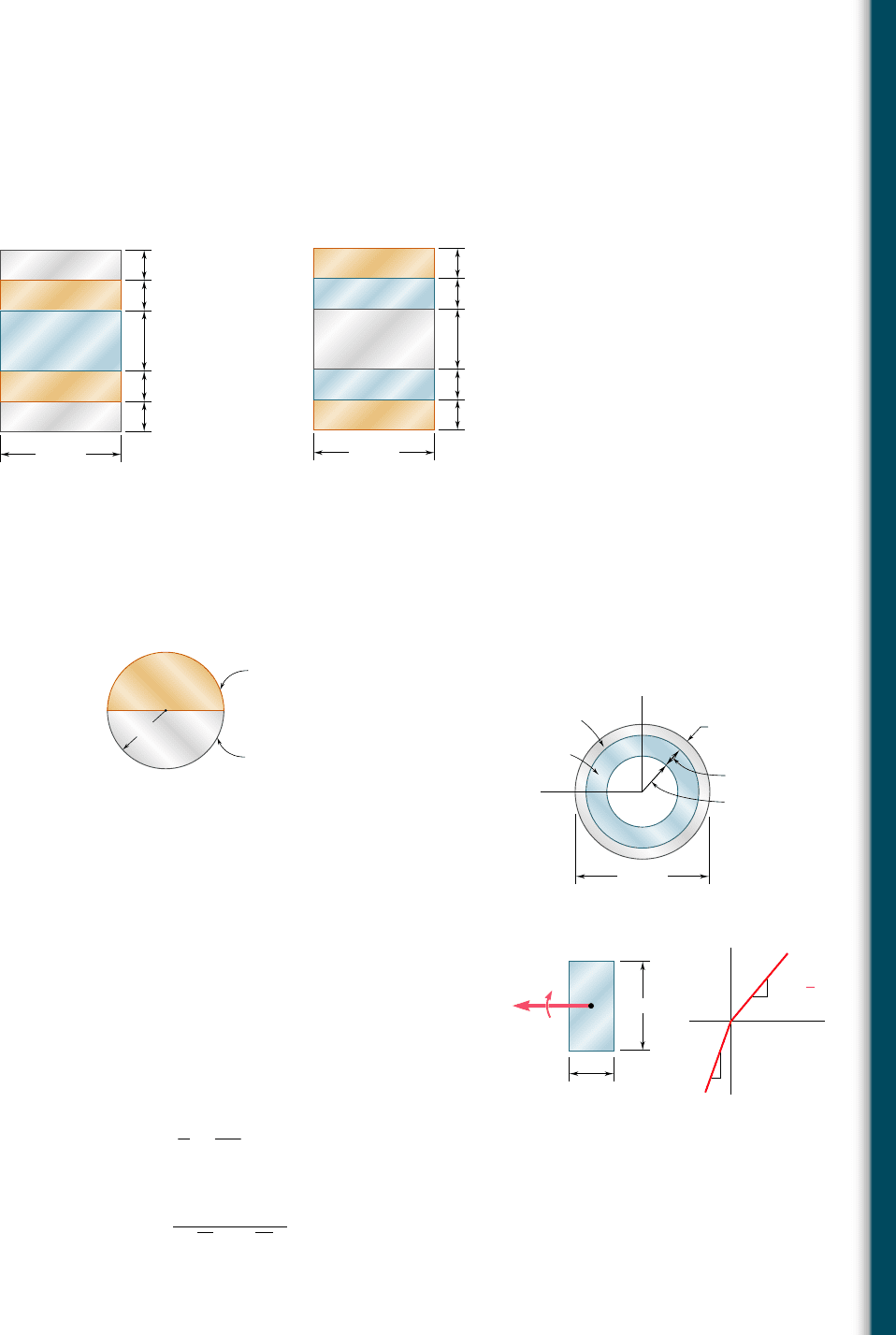
4.55 and 4.56 Five metal strips, each 40 mm wide, are bonded
together to form the composite beam shown. The modulus of elas-
ticity is 210 GPa for the steel, 105 GPa for the brass, and 70 GPa
for the aluminum. Knowing that the beam is bent about a horizon-
tal axis by a couple of moment 1800 N ? m, determine (a) the
maximum stress in each of the three metals, (b) the radius of cur-
vature of the composite beam.
Aluminum
Brass
Steel
Brass
Aluminum
40 mm
10 mm
10 mm
10 mm
10 mm
20 mm
Fig. P4.55
Brass
Steel
Aluminum
Steel
Brass
40 mm
10 mm
10 mm
10 mm
10 mm
20 mm
Fig. P4.56
4.57 The composite beam shown is formed by bonding together a brass
rod and an aluminum rod of semicircular cross sections. The mod-
ulus of elasticity is 15 3 10
6
psi for the brass and 10 3 10
6
psi for
the aluminum. Knowing that the composite beam is bent about a
horizontal axis by couples of moment 8 kip ? in., determine the
maximum stress (a) in the brass, (b) in the aluminum.
Brass
Aluminum
0.8 in.
Fig. P4.57
Steel
38 mm
10 mm
z
y
3 mm
6 mm
Aluminum
Fig. P4.58
50 mm
100 mm
E
t
E
c
1
2
E
c
M
Fig. P4.59
4.58 A steel pipe and an aluminum pipe are securely bonded together to
form the composite beam shown. The modulus of elasticity is 200 GPa
for the steel and 70 GPa for the aluminum. Knowing that the com-
posite beam is bent by a couple of moment 500 N ? m, determine
the maximum stress (a) in the aluminum, (b) in the steel.
4.59 The rectangular beam shown is made of a plastic for which the
value of the modulus of elasticity in tension is one-half of its value
in compression. For a bending moment M 5 600 N ? m, determine
the maximum (a) tensile stress, (b) compressive stress.
*4.60 A rectangular beam is made of material for which the modulus of
elasticity is E
t
in tension and E
c
in compression. Show that the
curvature of the beam in pure bending is
1
r
5
M
E
r
I
where
E
r
5
4E
t
E
c
1
1E
t
1 1E
c
2
2
bee80288_ch04_220-313.indd Page 253 10/26/10 4:28:53 PM user-f499bee80288_ch04_220-313.indd Page 253 10/26/10 4:28:53 PM user-f499 /Volumes/201/MHDQ251/bee80288_disk1of1/0073380288/bee80288_pagefiles/Volumes/201/MHDQ251/bee80288_disk1of1/0073380288/bee80288_pagefiles
Apago PDF Enhancer
254
Pure Bending
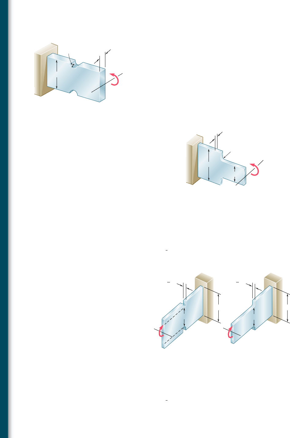
4.61 Semicircular grooves of radius r must be milled as shown in the
sides of a steel member. Using an allowable stress of 60 MPa,
determine the largest bending moment that can be applied to the
member when (a) r 5 9 mm, (b) r 5 18 mm.
4.62 Semicircular grooves of radius r must be milled as shown in the
sides of a steel member. Knowing that M 5 450 N ? m, determine
the maximum stress in the member when the radius r of the semi-
circular grooves is (a) r 5 9 mm, (b) r 5 18 mm.
4.63 Knowing that the allowable stress for the beam shown is 90 MPa,
determine the allowable bending moment M when the radius r of
the fillets is (a) 8 mm, (b) 12 mm.
r
M
108 mm
18 mm
Fig. P4.61 and P4.62
r
80 mm
40 mm
8 mm
M
Fig. P4.63 and P4.64
4.64 Knowing that M 5 250 N ? m, determine the maximum stress in the
beam shown when the radius r of the fillets is (a) 4 mm, (b) 8 mm.
4.65 The allowable stress used in the design of a steel bar is 12 ksi. Deter-
mine the largest couple M that can be applied to the bar (a) if the
bar is designed with grooves having semicircular portions of radius
r 5
3
4
in., as shown in Fig. a, (b) if the bar is redesigned by removing
the material above and below the dashed lines as shown in Fig. b.
7.5 in.
5 in.
in.
7
8
M
7.5 in.
5 in.
in.
7
8
M
(a)(b)
Fig. P4.65 and P4.66
4.66 A couple of moment M 5 20 kip ? in. is to be applied to the end
of a steel bar. Determine the maximum stress in the bar (a) if the
bar is designed with grooves having semicircular portions of radius
r 5
1
2
in., as shown in Fig. a, (b) if the bar is redesigned by removing
the material above and below the dashed lines as shown in Fig. b.
bee80288_ch04_220-313.indd Page 254 10/26/10 4:29:04 PM user-f499bee80288_ch04_220-313.indd Page 254 10/26/10 4:29:04 PM user-f499 /Volumes/201/MHDQ251/bee80288_disk1of1/0073380288/bee80288_pagefiles/Volumes/201/MHDQ251/bee80288_disk1of1/0073380288/bee80288_pagefiles
Apago PDF Enhancer
255
*4.8 PLASTIC DEFORMATIONS
When we derived the fundamental relation s
x
5 2MyyI in Sec. 4.4,
we assumed that Hooke’s law applied throughout the member. If the
yield strength is exceeded in some portion of the member, or if the
material involved is a brittle material with a nonlinear stress-strain
diagram, this relation ceases to be valid. The purpose of this section
is to develop a more general method for the determination of the
distribution of stresses in a member in pure bending, which can be
used when Hooke’s law does not apply.
We first recall that no specific stress-strain relationship was
assumed in Sec. 4.3, when we proved that the normal strain P
x
varies
linearly with the distance y from the neutral surface. Thus, we can
still use this property in our present analysis and write
P
x
52
y
c
P
m
(4.10)
where y represents the distance of the point considered from the
neutral surface, and c the maximum value of y.
However, we cannot assume anymore that, in a given section,
the neutral axis passes through the centroid of that section, since
this property was derived in Sec. 4.4 under the assumption of elastic
deformations. In general, the neutral axis must be located by trial
and error, until a distribution of stresses has been found, that satis-
fies Eqs. (4.1) and (4.3) of Sec. 4.2. However, in the particular case
of a member possessing both a vertical and a horizontal plane of
symmetry, and made of a material characterized by the same stress-
strain relation in tension and in compression, the neutral axis will
coincide with the horizontal axis of symmetry of the section. Indeed,
the properties of the material require that the stresses be symmetric
with respect to the neutral axis, i.e., with respect to some horizontal
axis, and it is clear that this condition will be met, and Eq. (4.1)
satisfied at the same time, only if that axis is the horizontal axis of
symmetry itself.
Our analysis will first be limited to the special case we have
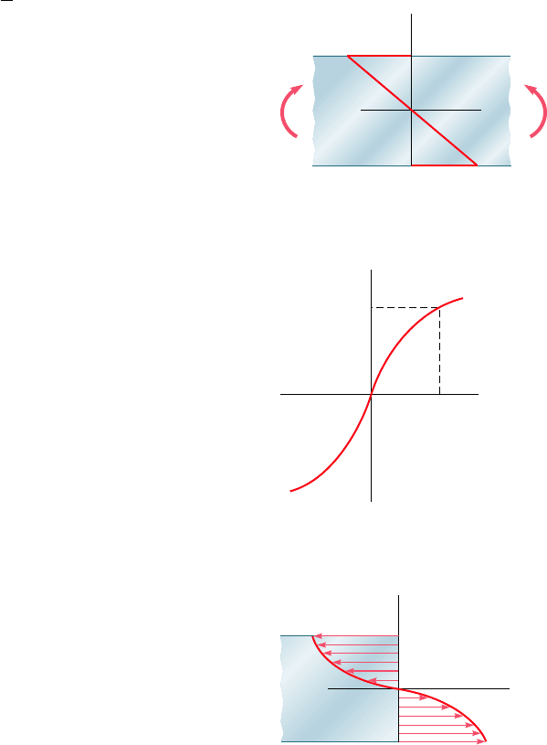
just described. The distance y in Eq. (4.10) is thus measured from
the horizontal axis of symmetry z of the cross section, and the dis-
tribution of strain P
x
is linear and symmetric with respect to that axis
(Fig. 4.30). On the other hand, the stress-strain curve is symmetric
with respect to the origin of coordinates (Fig. 4.31).
The distribution of stresses in the cross section of the member,
i.e., the plot of s
x
versus y, is obtained as follows. Assuming that s
max
has been specified, we first determine the corresponding value of P
m
from the stress-strain diagram and carry this value into Eq. (4.10).
Then, for each value of y, we determine the corresponding value of P
x
from Eq. (4.10) or Fig. 4.30, and obtain from the stress-strain diagram
of Fig. 4.31 the stress s
x
corresponding to this value of P
x
. Plotting s
x
against y yields the desired distribution of stresses (Fig. 4.32).
We now recall that, when we derived Eq. (4.3) in Sec. 4.2, we
assumed no particular relation between stress and strain. We can there-
fore use Eq. (4.3) to determine the bending moment M corresponding
to the stress distribution obtained in Fig. 4.32. Considering the particular
4.8 Plastic Deformations
z
– c
–
m
m
x
MM'
y
c
Fig. 4.30 Linear strain distribution in
beam.
0
x
m
x
max
Fig. 4.31 Nonlinear stress-
strain material diagram.
y
c
– c
max
x
Fig. 4.32 Nonlinear stress
distribution in beam.
bee80288_ch04_220-313.indd Page 255 11/11/10 3:03:13 PM user-f499bee80288_ch04_220-313.indd Page 255 11/11/10 3:03:13 PM user-f499 /Users/user-f499/Desktop/Temp Work/Don't Delete Job/MHDQ251:Beer:201/ch04/Users/user-f499/Desktop/Temp Work/Don't Delete Job/MHDQ251:Beer:201/ch04
Apago PDF Enhancer
256
Pure Bending
case of a member with a rectangular cross section of width b, we
express the element of area in Eq. (4.3) as dA 5 b dy and write
M 52b
#
c
2c
ys
x
dy
(4.30)
where s
x
is the function of y plotted in Fig. 4.32. Since s
x
is an odd
function of y, we can write Eq. (4.30) in the alternative form
M 522b
#
c
0
ys
x
dy
(4.31)
If s
x
is a known analytical function of P
x
, Eq. (4.10) can be
used to express s
x
as a function of y, and the integral in (4.31)
can be determined analytically. Otherwise, the bending moment
M can be obtained through a numerical integration. This computa-
tion becomes more meaningful if we note that the integral in
Eq. (4.31) represents the first moment with respect to the hori-
zontal axis of the area in Fig. 4.32 that is located above the hori-
zontal axis and is bounded by the stress-distribution curve and the
vertical axis.
An important value of the bending moment is the ultimate
bending moment M
U
that causes failure of the member. This value
can be determined from the ultimate strength s
U
of the material by
choosing s
max
5 s
U
and carrying out the computations indicated
earlier. However, it is found more convenient in practice to deter-
mine M
U
experimentally for a specimen of a given material. Assum-
ing a fictitious linear distribution of stresses, Eq. (4.15) is then used
to determine the corresponding maximum stress R
B
:
R
B
5
M
U
c
I
(4.32)
The fictitious stress R
B
is called the modulus of rupture in bending
of the given material. It can be used to determine the ultimate bend-
ing moment M
U
of a member made of the same material and having
a cross section of the same shape, but of different dimensions, by
solving Eq. (4.32) for M
U
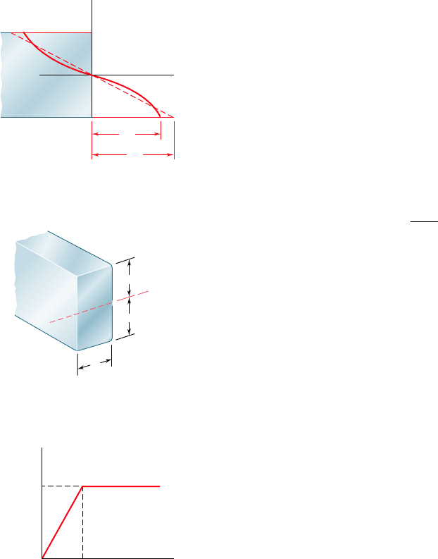
. Since, in the case of a member with a
rectangular cross section, the actual and the fictitious linear stress
distributions shown in Fig. 4.33 must yield the same value M
U
for the
ultimate bending moment, the areas they define must have the same
first moment with respect to the horizontal axis. It is thus clear that
the modulus of rupture R
B
will always be larger than the actual ulti-
mate strength s
U
.
*4.9 MEMBERS MADE OF AN ELASTOPLASTIC MATERIAL
In order to gain a better insight into the plastic behavior of a mem-
ber in bending, let us consider the case of a member made of an
elastoplastic material and first assume the member to have a rectan-
gular cross section of width b and depth 2c (Fig. 4.34). We recall
from Sec. 2.17 that the stress-strain diagram for an idealized elasto-
plastic material is as shown in Fig. 4.35.
R
x
U
B
y
Fig. 4.33 Beam stress
distribution at ultimate moment M
U
.
c
b
c
N. A.
Fig. 4.34 Beam with
rectangular cross section.
Y
Y
Y
Fig. 4.35 Idealized steel
stress-strain diagram.
bee80288_ch04_220-313.indd Page 256 10/27/10 5:46:17 PM user-f499bee80288_ch04_220-313.indd Page 256 10/27/10 5:46:17 PM user-f499 /Users/user-f499/Desktop/Temp Work/Don't Delete Job/MHDQ251:Beer:201/ch04/Users/user-f499/Desktop/Temp Work/Don't Delete Job/MHDQ251:Beer:201/ch04
