Beer F.P., Johnston E.R., DeWolf J.T., Mazurek D.F. Mechanics of Materials
Подождите немного. Документ загружается.

Apago PDF Enhancer
307
Review and Summary
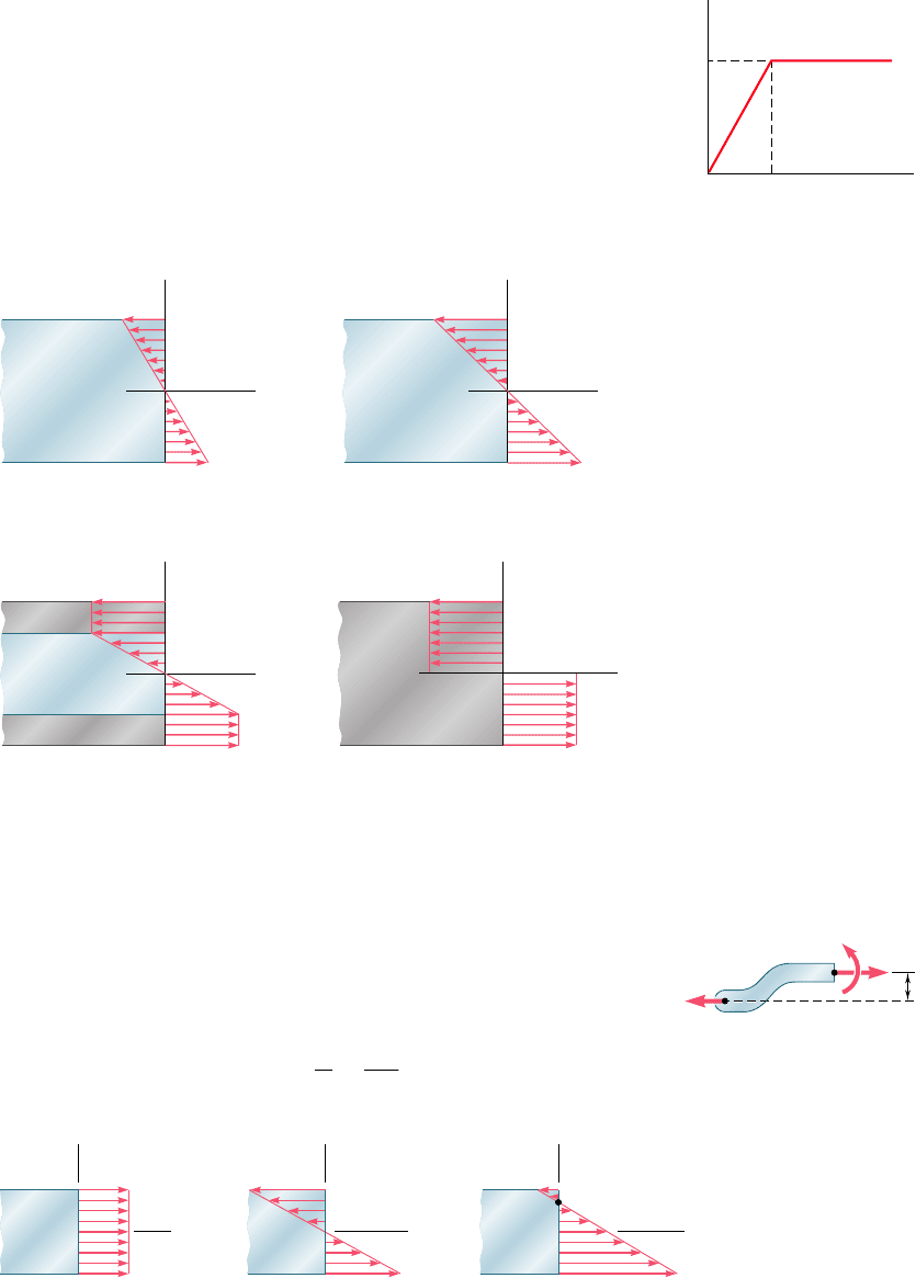
We next investigated members made of materials that do not
follow Hooke’s law [Sec. 4.8]. A rectangular beam made of an elas-
toplastic material (Fig. 4.82) was analyzed as the magnitude of the
bending moment was increased. The maximum elastic moment M
Y
occurred when yielding was initiated in the beam (Fig. 4.83). As the
bending moment was further increased, plastic zones developed and
the size of the elastic core of the member decreased [Sec. 4.9].
Finally the beam became fully plastic and we obtained the maximum
or plastic moment M
p
. In Sec. 4.11, we found that permanent defor-
mations and residual stresses remain in a member after the loads
that caused yielding have been removed.
Y
Y
Y
Fig. 4.82
y
C
C
y
x
x
C
N.A.
y
x
+=
Fig. 4.85
ELASTIC
y
c
c
x
max
m
(a) MM
ELASTIC
y
c
x
max
m
(b) MM
c
ELASTIC
PLASTIC
PLASTIC
y
c
c
x
max
(c) MM
PLASTIC
y
c
c
x
(d) MM
p
Fig. 4.83
Plastic deformations
In Sec. 4.12, we studied the stresses in members loaded eccentrically
in a plane of symmetry. Our analysis made use of methods developed
earlier. We replaced the eccentric load by a force-couple system
located at the centroid of the cross section (Fig. 4.84) and then
superposed stresses due to the centric load and the bending couple
(Fig. 4.85):
s
x
5
P
A
2
M
y
I
(4.50)
d
D
C
F
M
P'
A
Fig. 4.84
Eccentric axial loading
bee80288_ch04_220-313.indd Page 307 10/26/10 4:35:47 PM user-f499bee80288_ch04_220-313.indd Page 307 10/26/10 4:35:47 PM user-f499 /Volumes/201/MHDQ251/bee80288_disk1of1/0073380288/bee80288_pagefiles/Volumes/201/MHDQ251/bee80288_disk1of1/0073380288/bee80288_pagefiles
Apago PDF Enhancer
308
Pure Bending
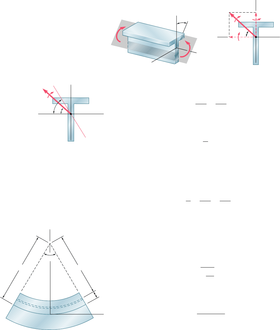
The bending of members of unsymmetric cross section was consid-
ered next [Sec. 4.13]. We found that the flexure formula may be
used, provided that the couple vector M is directed along one of the
principal centroidal axes of the cross section. When necessary we
resolved M into components along the principal axes and superposed
the stresses due to the component couples (Figs. 4.86 and 4.87).
s
x
52
M
z
y
I
z
1
M
y
z
I
y
(4.55)
For the couple M shown in Fig. 4.88, we determined the ori-
entation of the neutral axis by writing
tan f 5
I
z
I
y
tan u
(4.57)
The general case of eccentric axial loading was considered in
Sec. 4.14, where we again replaced the load by a force-couple system
located at the centroid. We then superposed the stresses due to the
centric load and two component couples directed along the principal
axes:
s
x
5
P
A
2
M
z
y
I
z
1
M
y
z
I
y
(4.58)
The chapter concluded with the analysis of stresses in curved mem-
bers (Fig. 4.89). While transverse sections remain plane when the
member is subjected to bending, we found that the stresses do not
vary linearly and the neutral surface does not pass through the cen-
troid of the section. The distance R from the center of curvature of
the member to the neutral surface was found to be
R 5
A
#
dA
r
(4.66)
where A is the area of the cross section. The normal stress at a dis-
tance y from the neutral surface was expressed as
s
x
52
M
y
Ae1R 2 y2
(4.70)
where M is the bending moment and e the distance from the cen-
troid of the section to the neutral surface.
Unsymmetric bending
M
x
z
y
M'
Fig. 4.86
M
M
y
M
z
y
z
C
Fig. 4.87
M
N. A.
C
y
z
Fig. 4.88
R
A
J
D
F
G
E
B
K
y
r
C
y
x
Fig. 4.89
General eccentric axial loading
Curved members
bee80288_ch04_220-313.indd Page 308 11/11/10 3:03:22 PM user-f499bee80288_ch04_220-313.indd Page 308 11/11/10 3:03:22 PM user-f499 /Users/user-f499/Desktop/Temp Work/Don't Delete Job/MHDQ251:Beer:201/ch04/Users/user-f499/Desktop/Temp Work/Don't Delete Job/MHDQ251:Beer:201/ch04
Apago PDF Enhancer
309
REVIEW PROBLEMS
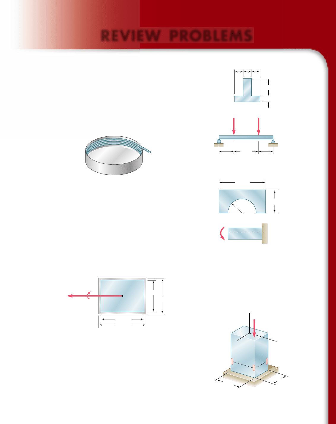
4.192 Two vertical forces are applied to a beam of the cross section
shown. Determine the maximum tensile and compressive stresses
in portion BC of the beam.
4.193 Straight rods of 6-mm diameter and 30-m length are stored by
coiling the rods inside a drum of 1.25-m inside diameter. Assum-
ing that the yield strength is not exceeded, determine (a) the maxi-
mum stress in a coiled rod, (b) the corresponding bending moment
in the rod. Use E 5 200 GPa.
DCBA
6 in.
2 in.
3 in.3 in.
15 kips 15 kips
3 in.
40 in. 40 in.
60 in.
Fig. P4.192
Fig. P4.193
4.194 Knowing that for the beam shown the allowable stress is 12 ksi in
tension and 16 ksi in compression, determine the largest couple M
that can be applied.
4.195 In order to increase corrosion resistance, a 2-mm-thick cladding of
aluminum has been added to a steel bar as shown. The modulus
of elasticity is 200 GPa for steel and 70 GPa for aluminum. For a
bending moment of 300 N ? m, determine (a) the maximum stress
in the steel, (b) the maximum stress in the aluminum, (c) the radius
of curvature of the bar.
1.2 in.
0.75 in.
2.4 in.
M
Fig. P4.194
46 mm
50 mm
M 300 N · m
30 mm
26 mm
Fig. P4.195
4.196 A single vertical force P is applied to a short steel post as shown.
Gages located at A, B, and C indicate the following strains:
P
A
5 2500 m P
B
5 21000 m P
C
5 2200 m
Knowing that E 5 29 3 10
6
psi, determine (a) the magnitude of
P, (b) the line of action of P, (c) the corresponding strain at the
hidden edge of the post, where x 5 22.5 in. and z 5 21.5 in.
P
C
B
A
y
z
x
3 in.
5 in.
Fig. P4.196
bee80288_ch04_220-313.indd Page 309 10/26/10 4:36:50 PM user-f499bee80288_ch04_220-313.indd Page 309 10/26/10 4:36:50 PM user-f499 /Volumes/201/MHDQ251/bee80288_disk1of1/0073380288/bee80288_pagefiles/Volumes/201/MHDQ251/bee80288_disk1of1/0073380288/bee80288_pagefiles
Apago PDF Enhancer
310
Pure Bending
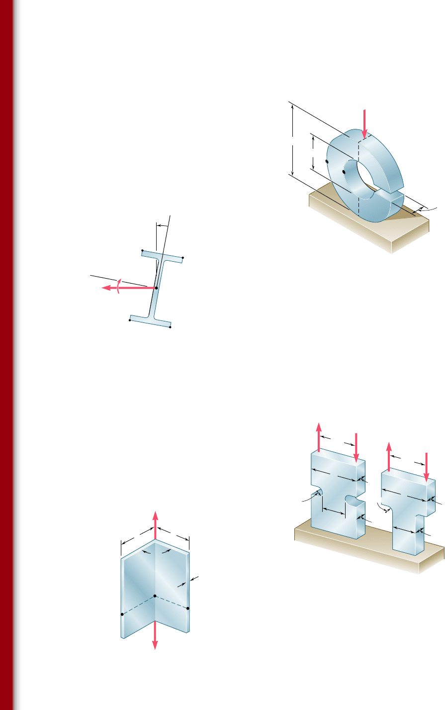
4.197 For the split ring shown, determine the stress at (a) point A,
(b) point B.
90 mm
40 mm
14 mm
2500 N
B
A
Fig. P4.197
E
D
M
8 kN · m
y'
z'
W
200
19.3
5
A
B
C
Fig. P4.198
4.198 A couple M of moment 8 kN ? m acting in a vertical plane is
applied to a W200 3 19.3 rolled-steel beam as shown. Determine
(a) the angle that the neutral axis forms with the horizontal plane,
(b) the maximum stress in the beam.
4.199 Determine the maximum stress in each of the two machine ele-
ments shown.
400 lb
400 lb
400 lb
400 lb
3
2.5
1.5
0.5
3
2.5
1.5
0.5
0.5
0.5
r ⫽ 0.3
r ⫽ 0.3
(a)
(b)
Fig. P4.199 All dimensions given in inches.
P'
P
A
B
C
a
a
t
90⬚
Fig. P4.200
4.200 The shape shown was formed by bending a thin steel plate. Assum-
ing that the thickness t is small compared to the length a of a side
of the shape, determine the stress (a) at A, (b) at B, (c) at C.
bee80288_ch04_220-313.indd Page 310 11/11/10 8:01:54 PM user-f499bee80288_ch04_220-313.indd Page 310 11/11/10 8:01:54 PM user-f499 /Users/user-f499/Desktop/Temp Work/Don't Delete Job/MHDQ251:Beer:201/ch04/Users/user-f499/Desktop/Temp Work/Don't Delete Job/MHDQ251:Beer:201/ch04
Apago PDF Enhancer
311
Review Problems
10 mm
120 mm
10 mm
120 mm
10 mm
M
Fig. P4.201
4.201 Three 120 3 10-mm steel plates have been welded together to
form the beam shown. Assuming that the steel is elastoplastic with
E 5 200 GPa and s
Y
5 300 MPa, determine (a) the bending
moment for which the plastic zones at the top and bottom of the
beam are 40 mm thick, (b) the corresponding radius of curvature
of the beam.
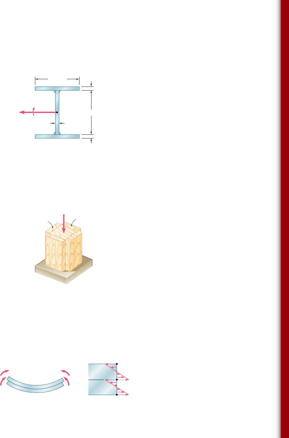
4.202 A short column is made by nailing four 1 3 4-in. planks to a
4 3 4-in. timber. Determine the largest compressive stress created
in the column by a 16-kip load applied as shown in the center
of the top section of the timber if (a) the column is as described,
(b) plank 1 is removed, (c) planks 1 and 2 are removed, (d) planks
1, 2, and 3 are removed, (e) all planks are removed.
11
2
4
3
16 kips
Fig. P4.202
4.203 Two thin strips of the same material and same cross section are
bent by couples of the same magnitude and glued together. After
the two surfaces of contact have been securely bonded, the couples
are removed. Denoting by s
1
the maximum stress and by r
1
the
radius of curvature of each strip while the couples were applied,
determine (a) the final stresses at points A, B, C, and D, (b) the
final radius of curvature.
M
1
M
1
M'
1
M'
1
A
C
B
D
1
1
1
1
Fig. P4.203
bee80288_ch04_220-313.indd Page 311 10/26/10 4:37:11 PM user-f499bee80288_ch04_220-313.indd Page 311 10/26/10 4:37:11 PM user-f499 /Volumes/201/MHDQ251/bee80288_disk1of1/0073380288/bee80288_pagefiles/Volumes/201/MHDQ251/bee80288_disk1of1/0073380288/bee80288_pagefiles
Apago PDF Enhancer
312
COMPUTER PROBLEMS
The following problems are designed to be solved with a computer.
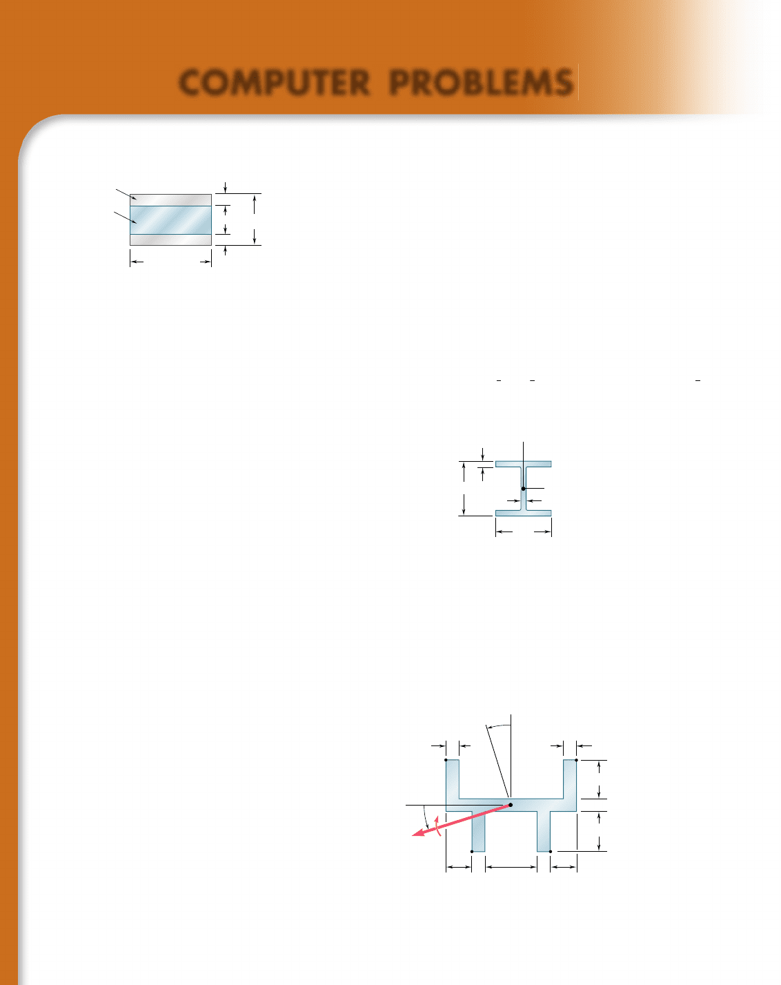
4.C1 Two aluminum strips and a steel strip are to be bonded together
to form a composite member of width b 5 60 mm and depth h 5 40 mm.
The modulus of elasticity is 200 GPa for the steel and 75 GPa for the alu-
minum. Knowing that M 5 1500 N ? m, write a computer program to cal-
culate the maximum stress in the aluminum and in the steel for values of a
from 0 to 20 mm using 2-mm increments. Using appropriate smaller incre-
ments, determine (a) the largest stress that can occur in the steel, (b) the
corresponding value of a.
4.C2 A beam of the cross section shown, made of a steel that is assumed
to be elastoplastic with a yield strength s
Y
and a modulus of elasticity E, is
bent about the x axis. (a) Denoting by y
Y
the half thickness of the elastic core,
write a computer program to calculate the bending moment M and the radius
of curvature r for values of y
Y
from
1
2
d to
1
6
d using decrements equal to
1
2
t
f
.
Neglect the effect of fillets. (b) Use this program to solve Prob. 4.201.
b
60 mm
h
40 mm
a
a
Steel
Aluminum
Fig. P4.C1
d
x
y
t
f
t
w
b
f
Fig. P4.C2
4.C3 An 8-kip ? in. couple M is applied to a beam of the cross section
shown in a plane forming an angle b with the vertical. Noting that the cen-
troid of the cross section is located at C and that the y and z axes are principal
axes, write a computer program to calculate the stress at A, B, C, and D for
values of b from 0 to 1808 using 108 increments. (Given: I
y
5 6.23 in
4
and
I
z
5 1.481 in
4
.)
z
0.40.4
1.6
1.2
0.4
1.2
0.4 0.8
Dimensions in inches
0.40.8
B
E
D
A
y
M
C
Fig. P4.C3
bee80288_ch04_220-313.indd Page 312 10/26/10 4:37:17 PM user-f499bee80288_ch04_220-313.indd Page 312 10/26/10 4:37:17 PM user-f499 /Volumes/201/MHDQ251/bee80288_disk1of1/0073380288/bee80288_pagefiles/Volumes/201/MHDQ251/bee80288_disk1of1/0073380288/bee80288_pagefiles
Apago PDF Enhancer
313
Computer Problems
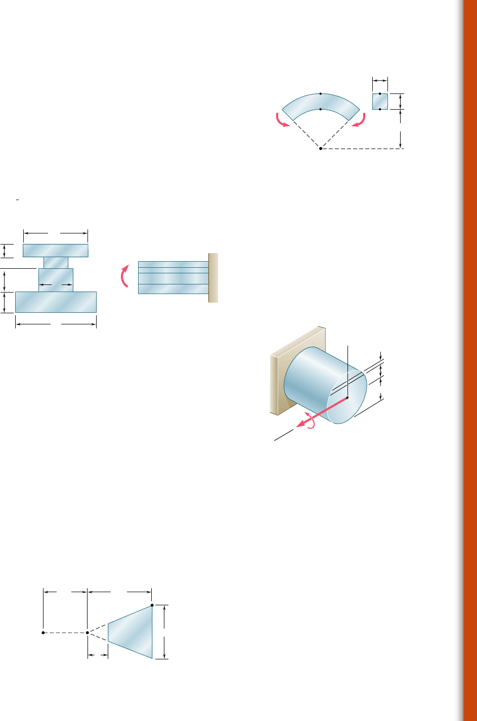
4.C4 Couples of moment M 5 2 kN ? m are applied as shown to a
curved bar having a rectangular cross section with h 5 100 mm and b 5
25 mm. Write a computer program and use it to calculate the stresses at
points A and B for values of the ratio r
1
/h from 10 to 1 using decrements
of 1, and from 1 to 0.1 using decrements of 0.1. Using appropriate smaller
increments, determine the ratio r
1
/h for which the maximum stress in the
curved bar is 50% larger than the maximum stress in a straight bar of the
same cross section.
4.C5 The couple M is applied to a beam of the cross section shown.
(a) Write a computer program that, for loads expressed in either SI or
U.S. customary units, can be used to calculate the maximum tensile and
compressive stresses in the beam. (b) Use this program to solve Probs. 4.10,
4.11, and 4.192.
B
b
r
1
M'
M
A
A
B
C
h
Fig. P4.C4
M
h
1
h
2
b
1
h
n
b
n
b
2
Fig. P4.C5
4.C6 A solid rod of radius c 5 1.2 in. is made of a steel that is assumed
to be elastoplastic with E 5 29,000 ksi and s
Y
5 42 ksi. The rod is subjected
to a couple of moment M that increases from zero to the maximum elastic
moment M
Y
and then to the plastic moment M
p
. Denoting by y
Y
the half
thickness of the elastic core, write a computer program and use it to calcu-
late the bending moment M and the radius of curvature r for values of y
Y
from 1.2 in. to 0 using 0.2-in. decrements. (Hint: Divide the cross section
into 80 horizontal elements of 0.03-in. height.)
4.C7 The machine element of Prob. 4.182 is to be redesigned by remov-
ing part of the triangular cross section. It is believed that the removal of a
small triangular area of width a will lower the maximum stress in the ele-
ment. In order to verify this design concept, write a computer program to
calculate the maximum stress in the element for values of a from 0 to 1 in.
using 0.1-in. increments. Using appropriate smaller increments, determine
the distance a for which the maximum stress is as small as possible and the
corresponding value of the maximum stress.
3 in.2 in.
2.5 in.C
B
a
A
Fig. P4.C7
c
z
y
y
M
y
Fig. P4.C6
bee80288_ch04_220-313.indd Page 313 10/26/10 4:37:28 PM user-f499bee80288_ch04_220-313.indd Page 313 10/26/10 4:37:28 PM user-f499 /Volumes/201/MHDQ251/bee80288_disk1of1/0073380288/bee80288_pagefiles/Volumes/201/MHDQ251/bee80288_disk1of1/0073380288/bee80288_pagefiles
Apago PDF Enhancer
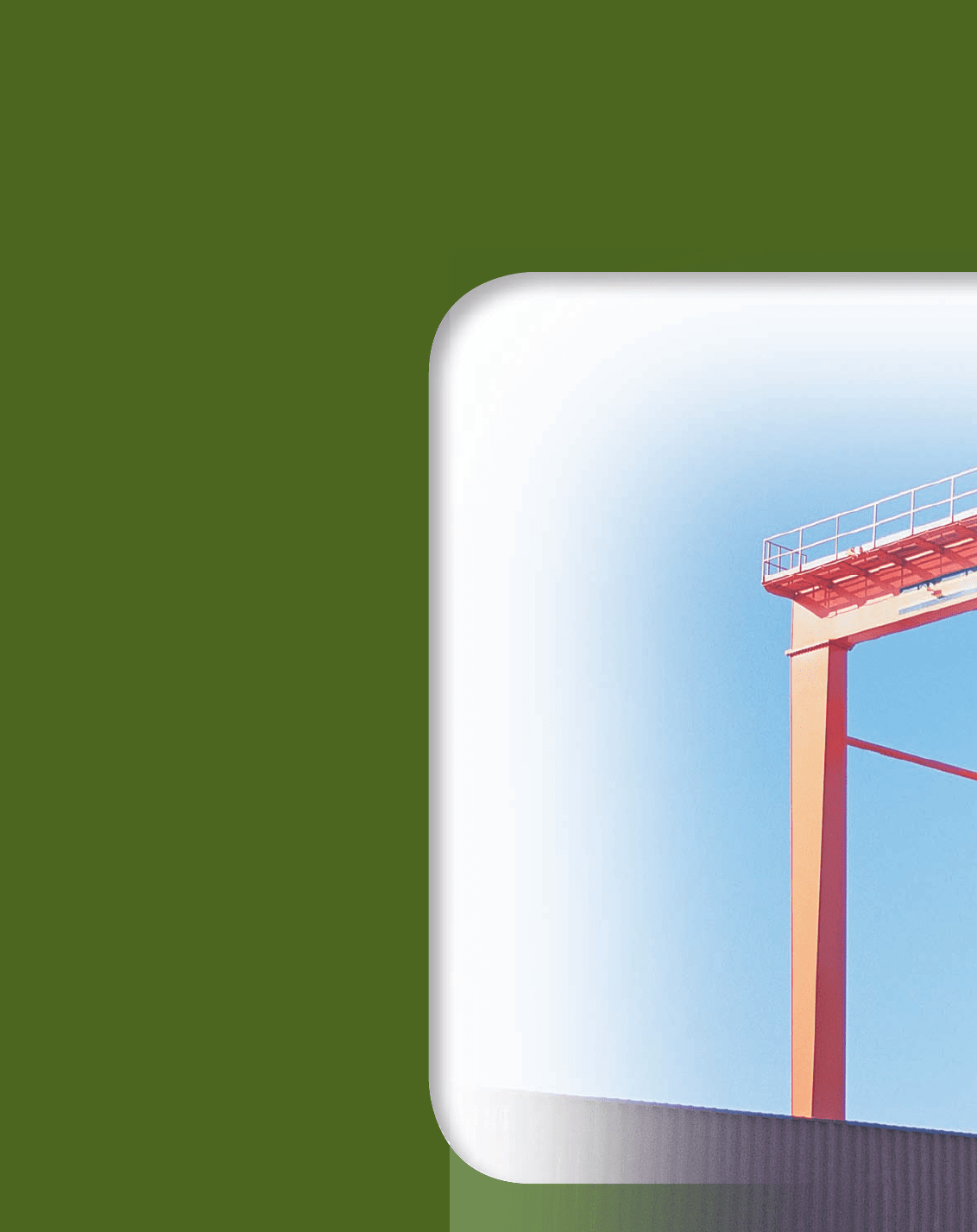
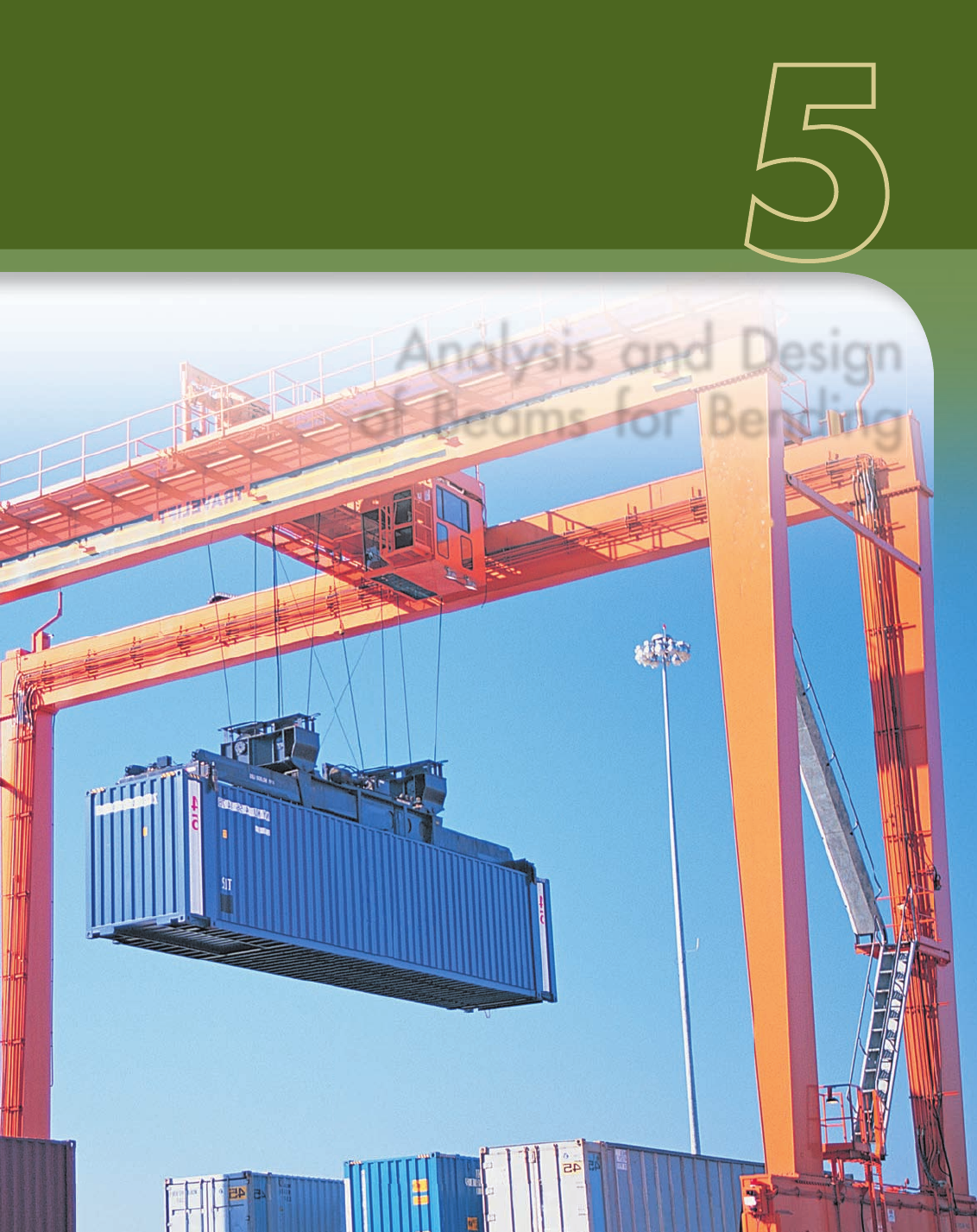
The beams supporting the multiple
overhead cranes system shown in this
picture are subjected to transverse
loads causing the beams to bend. The
normal stresses resulting from such
loadings will be determined in this
chapter.
314
bee80288_ch05_314-379.indd Page 314 10/27/10 9:48:37 PM user-f499bee80288_ch05_314-379.indd Page 314 10/27/10 9:48:37 PM user-f499 /Volumes/201/MHDQ251/bee80288_disk1of1/0073380288/bee80288_pagefiles/Volumes/201/MHDQ251/bee80288_disk1of1/0073380288/bee80288_pagefiles
Apago PDF Enhancer
CHAPTER
315
Analysis and Design
of Beams for Bending
bee80288_ch05_314-379.indd Page 315 10/27/10 9:50:57 PM user-f499bee80288_ch05_314-379.indd Page 315 10/27/10 9:50:57 PM user-f499 /Volumes/201/MHDQ251/bee80288_disk1of1/0073380288/bee80288_pagefiles/Volumes/201/MHDQ251/bee80288_disk1of1/0073380288/bee80288_pagefiles
Apago PDF Enhancer
316
Chapter 5 Analysis and Design
of Beams for Bending
5.1 Introduction
5.2 Shear and Bending-Moment
Diagrams
5.3 Relations Among Load, Shear,
and Bending Moment
5.4 Design of Prismatic Beams for
Bending
*5.5 Using Singularity Functions to
Determine Shear and Bending
Moment in a Beam
*5.6 Nonprismatic Beams
5.1 INTRODUCTION
This chapter and most of the next one will be devoted to the analysis
and the design of beams, i.e., structural members supporting loads
applied at various points along the member. Beams are usually long,
straight prismatic members, as shown in the photo on the previous
page. Steel and aluminum beams play an important part in both struc-
tural and mechanical engineering. Timber beams are widely used in
home construction (Photo 5.1). In most cases, the loads are perpen-
dicular to the axis of the beam. Such a transverse loading causes only
bending and shear in the beam. When the loads are not at a right
angle to the beam, they also produce axial forces in the beam.
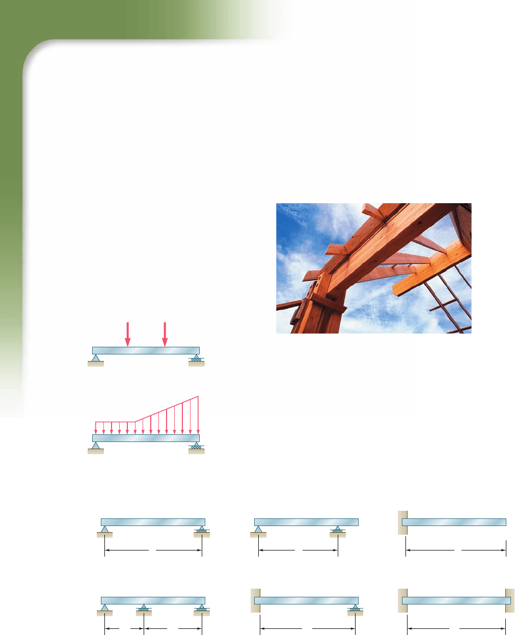
Photo 5.1 Timber beams used in residential
dwelling.
CB
P
1
(a) Concentrated loads
w
P
2
A
D
(b) Distributed load
A
B
C
Fig. 5.1 Transversely loaded
beams.
The transverse loading of a beam may consist of concentrated
loads P
1
, P
2
, . . . , expressed in newtons, pounds, or their multiples,
kilonewtons and kips (Fig. 5.1a), of a distributed load w, expressed
in N/m, kN/m, lb/ft, or kips/ft (Fig. 5.1b), or of a combination of
both. When the load w per unit length has a constant value over part
of the beam (as between A and B in Fig. 5.1b), the load is said to
be uniformly distributed over that part of the beam.
Beams are classified according to the way in which they are
supported. Several types of beams frequently used are shown in
Fig. 5.2. The distance L shown in the various parts of the figure is
Fig. 5.2 Common beam support configurations.
L
(a) Simply supported beam
Statically
Determinate
Beams
Statically
Indeterminate
Beams
L
2
L
1
(d) Continuous beam
L
(b) Overhanging beam
L
Beam fixed at one end
and simply supported
at the other end
(e)
L
(c) Cantilever beam
L
( f ) Fixed beam
bee80288_ch05_314-379.indd Page 316 10/29/10 7:07:38 PM user-f499bee80288_ch05_314-379.indd Page 316 10/29/10 7:07:38 PM user-f499 /Volumes/201/MHDQ251/bee80288_disk1of1/0073380288/bee80288_pagefiles/Volumes/201/MHDQ251/bee80288_disk1of1/0073380288/bee80288_pagefiles
