Beer F.P., Johnston E.R., DeWolf J.T., Mazurek D.F. Mechanics of Materials
Подождите немного. Документ загружается.

Apago PDF Enhancer
337
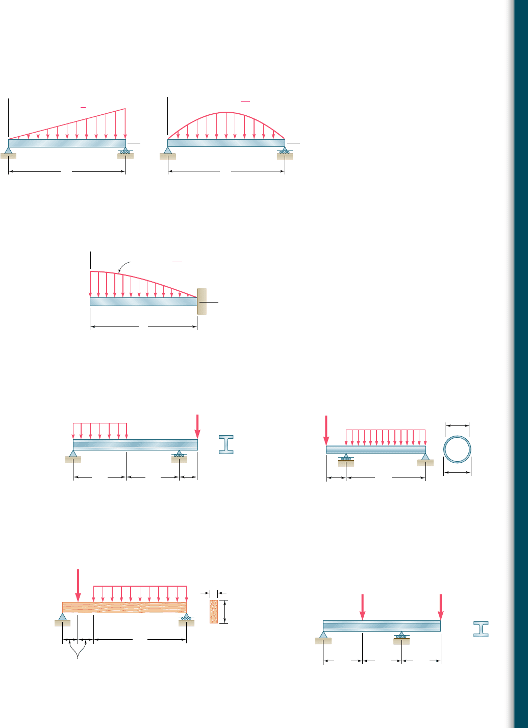
5.51 and 5.52 Determine (a) the equations of the shear and
bending-moment curves for the beam and loading shown, (b) the
maximum absolute value of the bending moment in the beam.
B
x
w
w w
0
A
L
x
L
Fig. P5.51
B
x
w
w w
0
sin
A
L
x
L
Fig. P5.52
5.53 Determine (a) the equations of the shear and bending-moment
curves for the beam and loading shown, (b) the maximum absolute
value of the bending moment in the beam.
w
A
L
B
x
w w
0
cos
x
2L
Fig. P5.53
CD
A
B
6 ft 6 ft
2 ft
2 kips/ft
6 kips
W8 31
Fig. P5.54
C
A
B
1 m
4 m
160 mm
140 mm
3 kN/m
2 kN
Fig. P5.55
5.56 and 5.57 Draw the shear and bending-moment diagrams for
the beam and loading shown and determine the maximum normal
stress due to bending.
AB
80 lb /ft
1600 lb
1.5 ft
9 ft
11.5 in.
1.5 in.
Fig. P5.56
B
DC
250 kN 150 kN
A
2 m 2 m 2 m
W410 114
Fig. P5.57
5.54 and 5.55 Draw the shear and bending-moment diagrams for
the beam and loading shown and determine the maximum normal
stress due to bending.
Problems
bee80288_ch05_314-379.indd Page 337 10/27/10 9:53:33 PM user-f499bee80288_ch05_314-379.indd Page 337 10/27/10 9:53:33 PM user-f499 /Volumes/201/MHDQ251/bee80288_disk1of1/0073380288/bee80288_pagefiles/Volumes/201/MHDQ251/bee80288_disk1of1/0073380288/bee80288_pagefiles
Apago PDF Enhancer
338
Analysis and Design of Beams for Bending
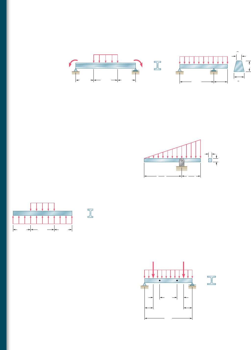
5.58 and 5.59 Draw the shear and bending-moment diagrams for
the beam and loading shown and determine the maximum normal
stress due to bending.
A
B
DC
80 kN/m
W250 80
1.2 m 1.2 m1.6 m
60 kN · m 12 kN · m
B
C
A
8 in.
20 in.
3 in.
800 lb/in.
2 in.
1
2
1 in.
1
4
Fig. P5.59Fig. P5.58
5.60 Beam AB, of length L and square cross section of side a, is sup-
ported by a pivot at C and loaded as shown. (a) Check that the
beam is in equilibrium. (b) Show that the maximum stress due to
bending occurs at C and is equal to w
0
L
2
y(1.5a)
3
.
B
a
a
A
2L
3
C
w
0
L
3
Fig. P5.60
A
C
BD
400 kN/m
W200 22.5
w
0
0.3 m 0.3 m0.4 m
Fig. P5.61
A
480 lb/ft
1 ft 1 ft
1.5 ft 1.5 ft
W8 31
8 ft
P
B
CDEF
Q
Fig. P5.62
5.61 Knowing that beam AB is in equilibrium under the loading shown,
draw the shear and bending-moment diagrams and determine the
maximum normal stress due to bending.
*5.62 The beam AB supports a uniformly distributed load of 480 lb/ft
and two concentrated loads P and Q. The normal stress due to
bending on the bottom edge of the lower flange is 114.85 ksi at
D and 110.65 ksi at E. (a) Draw the shear and bending-moment
diagrams for the beam. (b) Determine the maximum normal stress
due to bending that occurs in the beam.
bee80288_ch05_314-379.indd Page 338 10/27/10 9:53:49 PM user-f499bee80288_ch05_314-379.indd Page 338 10/27/10 9:53:49 PM user-f499 /Volumes/201/MHDQ251/bee80288_disk1of1/0073380288/bee80288_pagefiles/Volumes/201/MHDQ251/bee80288_disk1of1/0073380288/bee80288_pagefiles
Apago PDF Enhancer
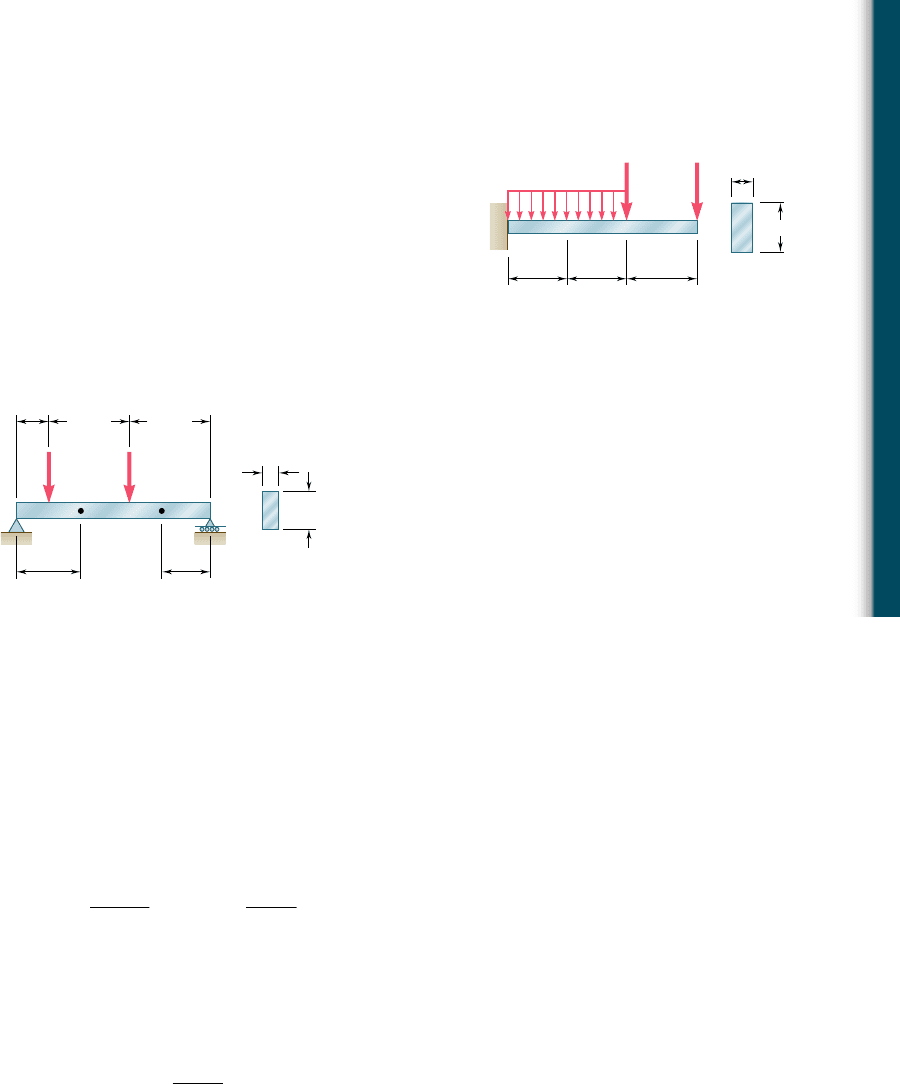
*5.63 Beam AB supports a uniformly distributed load of 2 kN/m and two
concentrated loads P and Q. It has been experimentally deter-
mined that the normal stress due to bending in the bottom edge
of the beam is 256.9 MPa at A and 229.9 MPa at C. Draw the
shear and bending-moment diagrams for the beam and determine
the magnitudes of the loads P and Q.
*5.64 The beam AB supports two concentrated loads P and Q. The
normal stress due to bending on the bottom edge of the beam
is 155 MPa at D and 137.5 MPa at F. (a) Draw the shear and
bending-moment diagrams for the beam. (b) Determine the maxi-
mum normal stress due to bending that occurs in the beam.
CD
B
A
2 kN/m
P
0.1 m 0.1 m 0.125 m
36 mm
18 mm
Q
Fig. P5.63
Fig. P5.64
0.4 m
PQ
24 mm
0.2 m
0.5 m 0.5 m
60 mm
A
CDEF
B
0.3 m
5.4 DESIGN OF PRISMATIC BEAMS FOR BENDING
As indicated in Sec. 5.1, the design of a beam is usually controlled by
the maximum absolute value |M|
max
of the bending moment that will
occur in the beam. The largest normal stress s
m
in the beam is found
at the surface of the beam in the critical section where |M|
max
occurs
and can be obtained by substituting |M|
max
for |M| in Eq. (5.1) or Eq.
(5.3).† We write
s
m
5
Z
M
Z
max
c
I
s
m
5
Z
M
Z
max
S
(5.19, 5.39)
A safe design requires that s
m
# s
all
, where s
all
is the allowable stress
for the material used. Substituting s
all
for s
m
in (5.39) and solving
for S yields the minimum allowable value of the section modulus for
the beam being designed:
S
min
5
Z
M
Z
max
s
a
ll
(5.9)
The design of common types of beams, such as timber beams
of rectangular cross section and rolled-steel beams of various cross-
sectional shapes, will be considered in this section. A proper proce-
dure should lead to the most economical design. This means that,
among beams of the same type and the same material, and other
†For beams that are not symmetrical with respect to their neutral surface, the largest of
the distances from the neutral surface to the surfaces of the beam should be used for c
in Eq. (5.1) and in the computation of the section modulus S 5 I/c.
5.4 Design of Prismatic Beams for Bending
339
bee80288_ch05_314-379.indd Page 339 10/27/10 9:53:54 PM user-f499bee80288_ch05_314-379.indd Page 339 10/27/10 9:53:54 PM user-f499 /Volumes/201/MHDQ251/bee80288_disk1of1/0073380288/bee80288_pagefiles/Volumes/201/MHDQ251/bee80288_disk1of1/0073380288/bee80288_pagefiles

Apago PDF Enhancer
340
Analysis and Design of Beams for Bending
things being equal, the beam with the smallest weight per unit
length—and, thus, the smallest cross-sectional area—should be
selected, since this beam will be the least expensive.
The design procedure will include the following steps†:
1. First determine the value of s
all
for the material selected from
a table of properties of materials or from design specifications.
You can also compute this value by dividing the ultimate strength
s
U
of the material by an appropriate factor of safety (Sec. 1.13).
Assuming for the time being that the value of s
all
is the same
in tension and in compression, proceed as follows.
2. Draw the shear and bending-moment diagrams corresponding
to the specified loading conditions, and determine the maximum
absolute value |M|
max
of the bending moment in the beam.
3. Determine from Eq. (5.9) the minimum allowable value S
min
of the section modulus of the beam.
4. For a timber beam, the depth h of the beam, its width b, or
the ratio hyb characterizing the shape of its cross section will
probably have been specified. The unknown dimensions may
then be selected by recalling from Eq. (4.19) of Sec. 4.4 that
b and h must satisfy the relation
1
6
bh
2
5 S $ S
min
.
5. For a rolled-steel beam, consult the appropriate table in Appen-
dix C. Of the available beam sections, consider only those with a
section modulus S $ S
min
and select from this group the section
with the smallest weight per unit length. This is the most eco-
nomical of the sections for which S $ S
min
. Note that this is not
necessarily the section with the smallest value of S (see Example
5.04). In some cases, the selection of a section may be limited by
other considerations, such as the allowable depth of the cross
section, or the allowable deflection of the beam (cf. Chap. 9).
The foregoing discussion was limited to materials for which s
all
is
the same in tension and in compression. If s
all
is different in tension
and in compression, you should make sure to select the beam section
in such a way that s
m
# s
all
for both tensile and compressive stresses.
If the cross section is not symmetric about its neutral axis, the largest
tensile and the largest compressive stresses will not necessarily occur in
the section where |M| is maximum. One may occur where M is maxi-
mum and the other where M is minimum. Thus, step 2 should include
the determination of both M
max
and M
min
, and step 3 should be modified
to take into account both tensile and compressive stresses.
Finally, keep in mind that the design procedure described in
this section takes into account only the normal stresses occurring on
the surface of the beam. Short beams, especially those made of tim-
ber, may fail in shear under a transverse loading. The determination
of shearing stresses in beams will be discussed in Chap. 6. Also, in
the case of rolled-steel beams, normal stresses larger than those con-
sidered here may occur at the junction of the web with the flanges.
This will be discussed in Chap. 8.
†We assume that all beams considered in this chapter are adequately braced to prevent
lateral buckling, and that bearing plates are provided under concentrated loads applied to
rolled-steel beams to prevent local buckling (crippling) of the web.
bee80288_ch05_314-379.indd Page 340 10/27/10 9:54:00 PM user-f499bee80288_ch05_314-379.indd Page 340 10/27/10 9:54:00 PM user-f499 /Volumes/201/MHDQ251/bee80288_disk1of1/0073380288/bee80288_pagefiles/Volumes/201/MHDQ251/bee80288_disk1of1/0073380288/bee80288_pagefiles
Apago PDF Enhancer
*Load and Resistance Factor Design. This alternative method
of design was briefly described in Sec. 1.13 and applied to mem-
bers under axial loading. It can readily be applied to the design of
beams in bending. Replacing in Eq. (1.26) the loads P
D
, P
L
, and
P
U
, respectively, by the bending moments M
D
, M
L
, and M
U
, we
write
g
D
M
D
1 g
L
M
L
# fM
U
(5.10)
The coefficients g
D
and g
L
are referred to as the load factors and
the coefficient f as the resistance factor. The moments M
D
and
M
L
are the bending moments due, respectively, to the dead and
the live loads, while M
U
is equal to the product of the ultimate
strength s
U
of the material and the section modulus S of the beam:
M
U
5 Ss
U
.
EXAMPLE 5.04
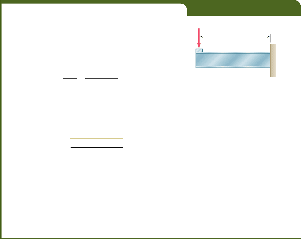
Select a wide-flange beam to support the 15-kip load as shown in Fig. 5.14.
The allowable normal stress for the steel used is 24 ksi.
1. The allowable normal stress is given: s
all
5 24 ksi.
2. The shear is constant and equal to 15 kips. The bending moment
is maximum at B. We have
ZMZ
max
5
1
15 kips
21
8 ft
2
5 120 kip ? ft 5 1440 kip ? in.
3. The minimum allowable section modulus is
S
min
5
ZMZ
max
s
a
ll
5
1440
k
ip ? in.
24 ksi
5 60.0 in
3
4. Referring to the table of Properties of Rolled-Steel Shapes in Appen-
dix C, we note that the shapes are arranged in groups of the same
depth and that in each group they are listed in order of decreasing
weight. We choose in each group the lightest beam having a section
modulus S 5 Iyc at least as large as S
min
and record the results in
the following table.
Shape S, in
3
W21 3 44 81.6
W18 3 50 88.9
W16 3 40 64.7
W14 3 43 62.6
W12 3 50 64.2
W10 3 54 60.0
The most economical is the W16 3 40 shape since it weighs only 40 lb/ft,
even though it has a larger section modulus than two of the other shapes.
We also note that the total weight of the beam will be (8 ft) 3 (40 lb) 5
320 lb. This weight is small compared to the 15,000-1b load and can be
neglected in our analysis.
15 kips
8 ft
A
B
Fig. 5.14
341
bee80288_ch05_314-379.indd Page 341 10/27/10 9:54:00 PM user-f499bee80288_ch05_314-379.indd Page 341 10/27/10 9:54:00 PM user-f499 /Volumes/201/MHDQ251/bee80288_disk1of1/0073380288/bee80288_pagefiles/Volumes/201/MHDQ251/bee80288_disk1of1/0073380288/bee80288_pagefiles
Apago PDF Enhancer
342
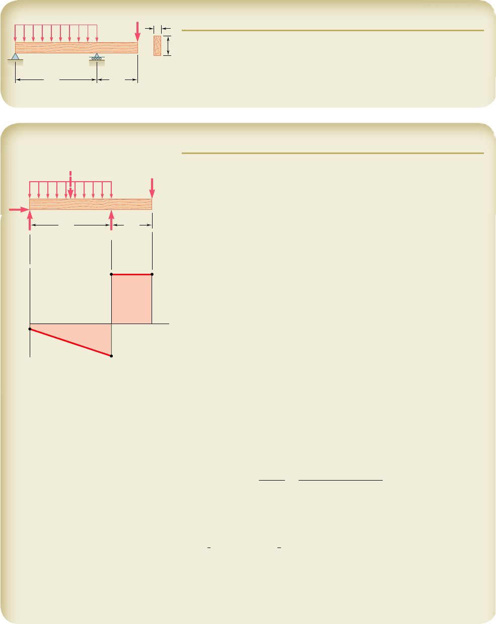
SAMPLE PROBLEM 5.7
A 12-ft-long overhanging timber beam AC with an 8-ft span AB is to be
designed to support the distributed and concentrated loads shown. Knowing
that timber of 4-in. nominal width (3.5-in. actual width) with a 1.75-ksi
allowable stress is to be used, determine the minimum required depth h of
the beam.
B
A
C
h
8 ft 4 ft
3.5 in.
400 lb/ft
4.5 kips
SOLUTION
Reactions. Considering the entire beam as a free body, we write
1l
oM
A
5 0: B18 ft22 13.2 kips214 ft22 14.5 kips2112 ft25 0
B 5 8.35 kips B 5 8.35 kipsx
1
y
oF
x
5 0:
A
x
5 0
1xoF
y
5 0: A
y
1 8.35 kips 2 3.2 kips 2 4.5 kips 5 0
A
y
520.65 kips A 5 0.65 kips w
Shear Diagram. The shear just to the right of A is V
A
5
A
y
5
20.65 kips. Since the change in shear between A and B is equal to minus the
area under the load curve between these two points, we obtain V
B
by writing
V
B
2 V
A
521400 lb/ft218 ft2523200 lb 523.20 kips
V
B
5 V
A
2 3.20 kips 520.65 kips 2 3.20 kips 523.85 kips.
The reaction at B produces a sudden increase of 8.35 kips in V, resulting in a
value of the shear equal to 4.50 kips to the right of B. Since no load is applied
between B and C, the shear remains constant between these two points.
Determination of |M|
max
. We first observe that the bending moment is
equal to zero at both ends of the beam: M
A
5 M
C
5 0. Between A and B the
bending moment decreases by an amount equal to the area under the shear
curve, and between B and C it increases by a corresponding amount. Thus, the
maximum absolute value of the bending moment is |M|
max
5
18.00 kip ? ft.
Minimum Allowable Section Modulus. Substituting into Eq. (5.9) the
given value of s
all
and the value of |M|
max
that we have found, we write
S
min
5
0M 0
max
s
a
ll
5
1
18 kip ? ft
21
12 in./ft
2
1.75 ksi
5 123.43 in
3
Minimum Required Depth of Beam. Recalling the formula developed
in part 4 of the design procedure described in Sec. 5.4 and substituting the
values of b and S
min
, we have
1
6
bh
2
$ S
min
1
6
13.5 in.2h
2
$ 123.43 in
3
h $ 14.546 in.
The minimum required depth of the beam is
h
5 14.55 in.
◀
Note: In practice, standard wood shapes are specified by nominal dimensions that
are slightly larger than actual. In this case, we would specify a 4-in. 3 16-in. member,
whose actual dimensions are 3.5 in. 3 15.25 in.
B
A
V
A
A
x
A
y
B
C
8 ft 4 ft
3.2 kips
4.5 kips
(⫺18)
(⫹18)
4.50
kips
⫺3.85 kips
⫺0.65
kips
CB
x
bee80288_ch05_314-379.indd Page 342 11/16/10 6:42:31 PM user-f499bee80288_ch05_314-379.indd Page 342 11/16/10 6:42:31 PM user-f499 /Volumes/201/MHDQ251/bee80288_disk1of1/0073380288/bee80288_pagefiles/Volumes/201/MHDQ251/bee80288_disk1of1/0073380288/bee80288_pagefiles
Apago PDF Enhancer
343
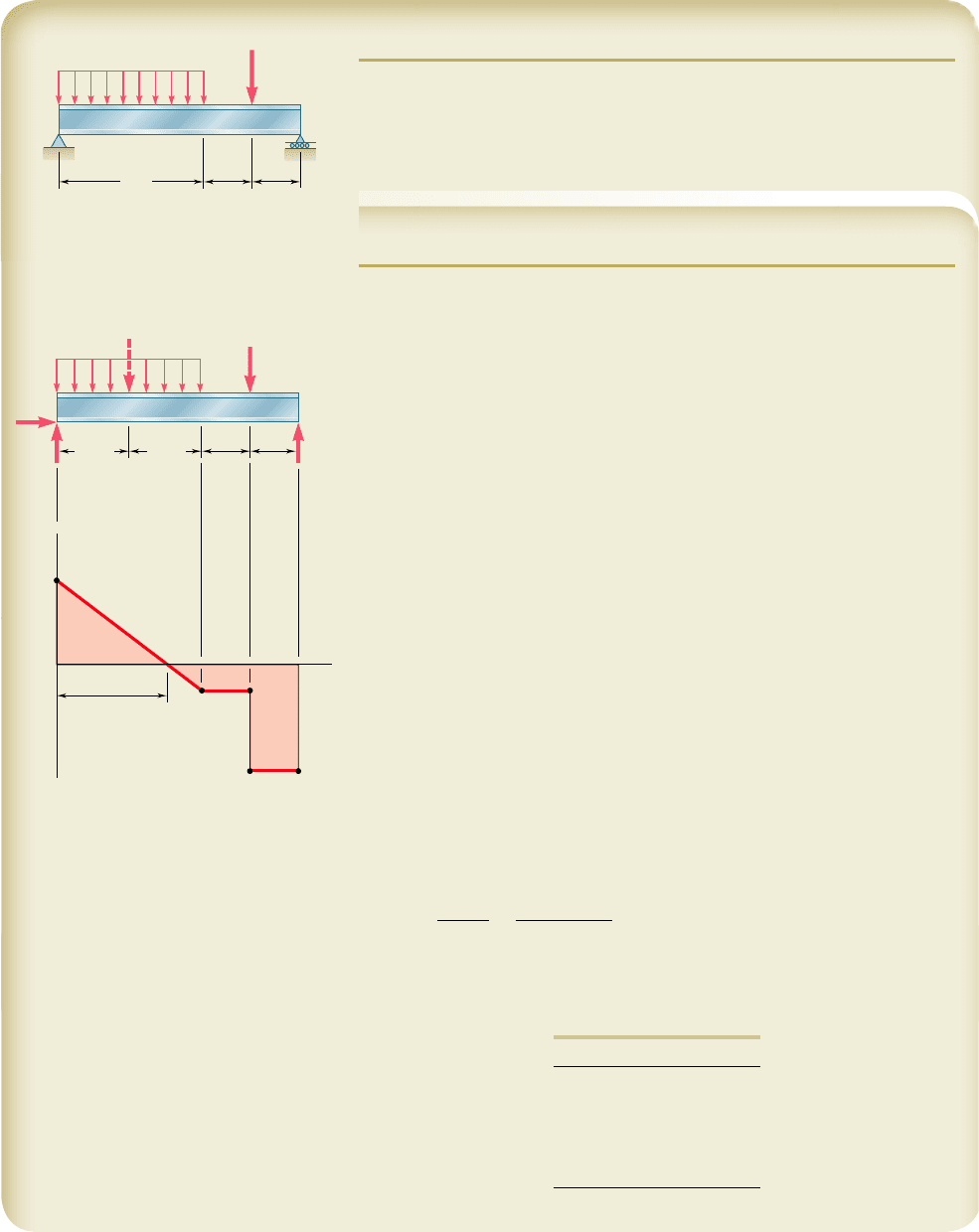
SAMPLE PROBLEM 5.8
A 5-m-long, simply supported steel beam AD is to carry the distributed and
concentrated loads shown. Knowing that the allowable normal stress for the
grade of steel to be used is 160 MPa, select the wide-flange shape that
should be used.
SOLUTION
Reactions. Considering the entire beam as a free body, we write
1loM
A
5 0: D15 m22 160 kN211.5 m22 150 kN214 m25 0
D 5 58
.
0 kN D 5 58.0 kNx
1
y
oF
x
5 0: A
x
5 0
1xoF
y
5 0: A
y
1 58.0 kN 2 60 kN 2 50 kN 5 0
A
y
5 52.0 kN A 5 52.0 kNx
Shear Diagram. The shear just to the right of A is V
A
5
A
y
5
152.0 kN. Since the change in shear between A and B is equal to minus
the area under the load curve between these two points, we have
V
B
5 52.0 kN 2 60 kN 528 kN
The shear remains constant between B and C, where it drops to 258 kN,
and keeps this value between C and D. We locate the section E of the beam
where V 5 0 by writing
V
E
2 V
A
52wx
0 2 52.0 kN 52120 kN/m2
x
Solving for x we find x 5 2.60 m.
Determination of |M|
max
. The bending moment is maximum at E,
where V 5 0. Since M is zero at the support A, its maximum value at E is
equal to the area under the shear curve between A and E. We have, there-
fore, |M|
max
5
M
E
5 67.6 kN ? m.
Minimum Allowable Section Modulus. Substituting into Eq. (5.9) the
given value of s
all
and the value of |M|
max
that we have found, we write
S
min
5
0
M
0
max
s
a
ll
5
67.6 kN ? m
160 MPa
5 422.5 3 10
26
m
3
5 422.5 3 10
3
mm
3
Selection of Wide-Flange Shape. From Appendix C we compile a
list of shapes that have a section modulus larger than S
min
and are also the
lightest shape in a given depth group.
Shape S, mm
3
W410 3 38.8 629
W360 3 32.9 475
W310 3 38.7 547
W250 3 44.8 531
W200 3 46.1 451
We select the lightest shape available, namely W360 3 32.9b
CB
D
1.5 m
52 kN
x ⫽ 2.6 m
⫺58 kN
⫺8 kN
(67.6)
1.5 m
1 m 1 m
50 kN
D
A
V
A
EB C D
x
A
x
A
y
60 kN
B
A
C
D
3 m
1 m 1 m
20 kN
50 kN
bee80288_ch05_314-379.indd Page 343 10/28/10 7:26:00 PM user-f499bee80288_ch05_314-379.indd Page 343 10/28/10 7:26:00 PM user-f499 /Volumes/201/MHDQ251/bee80288_disk1of1/0073380288/bee80288_pagefiles/Volumes/201/MHDQ251/bee80288_disk1of1/0073380288/bee80288_pagefiles
Apago PDF Enhancer
PROBLEMS
344
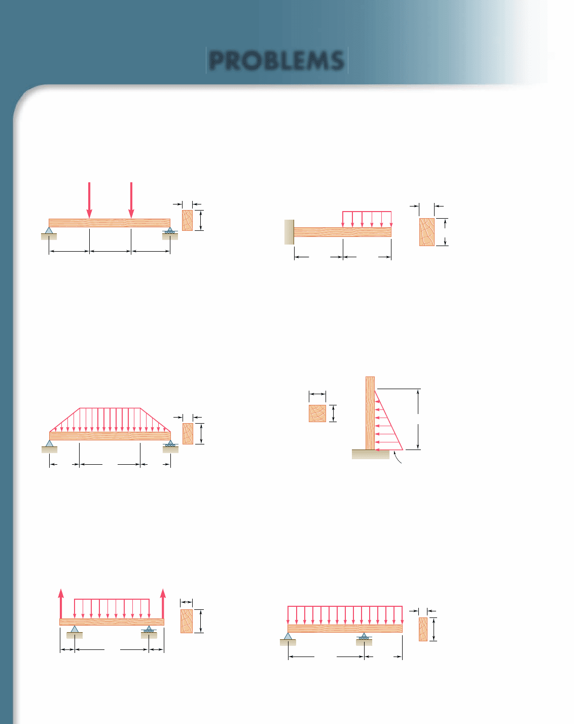
5.65 and 5.66 For the beam and loading shown, design the cross
section of the beam, knowing that the grade of timber used has an
allowable normal stress of 12 MPa.
5.67 and 5.68 For the beam and loading shown, design the cross
section of the beam, knowing that the grade of timber used has an
allowable normal stress of 1750 psi.
5.69 and 5.70 For the beam and loading shown, design the cross
section of the beam, knowing that the grade of timber used has an
allowable normal stress of 12 MPa.
1.8 kN 3.6 kN
CB
AD
h
0.8 m 0.8 m 0.8 m
40 mm
Fig. P5.65
A
B
C
h
1.2 m 1.2 m
125 mm
18 kN/m
Fig. P5.66
1.2 kips/ft
6 ft
a
a
B
A
Fig. P5.68
C
B
A
D
h
3 ft
6 ft
5 in.
1.5 kips/ft
3 ft
Fig. P5.67
A
B
150 mm
b
3 kN/m
C
2.4 m 1.2 m
Fig. P5.70
C
A
B
D
h
0.6 m 0.6 m
3 m
100 mm
6 kN/m
2.5 kN2.5 kN
Fig. P5.69
bee80288_ch05_314-379.indd Page 344 10/27/10 9:54:16 PM user-f499bee80288_ch05_314-379.indd Page 344 10/27/10 9:54:16 PM user-f499 /Volumes/201/MHDQ251/bee80288_disk1of1/0073380288/bee80288_pagefiles/Volumes/201/MHDQ251/bee80288_disk1of1/0073380288/bee80288_pagefiles
Apago PDF Enhancer
345
ProblemsProblems
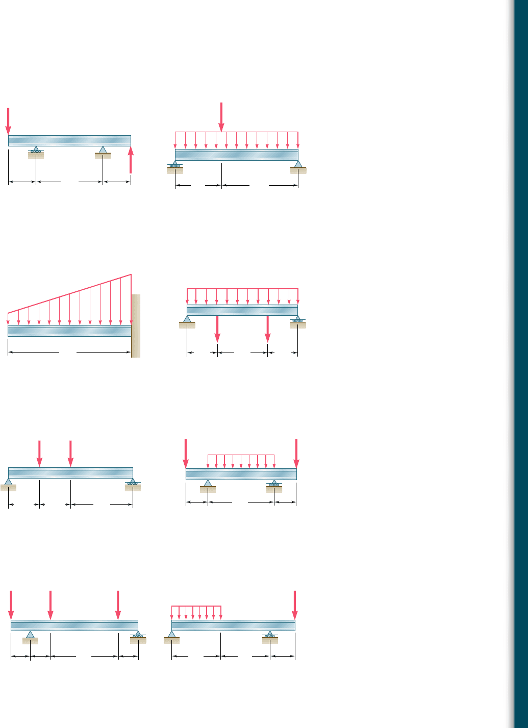
5.71 and 5.72 Knowing that the allowable stress for the steel used
is 24 ksi, select the most economical wide-flange beam to support
the loading shown.
Fig. P5.72
2.75 kips/ft
24 kips
B
A
C
9 ft 15 ft
5 ft
12 ft
5 ft
62 kips
62 kips
BC
A
D
Fig. P5.71
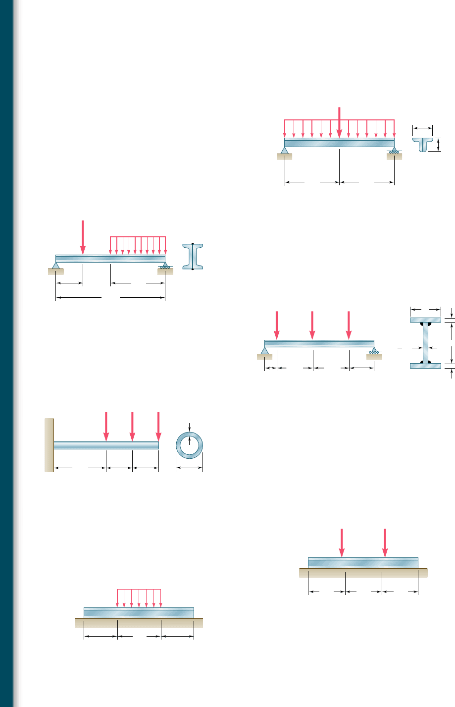
5.73 and 5.74 Knowing that the allowable stress for the steel used
is 160 MPa, select the most economical wide-flange beam to sup-
port the loading shown.
Fig. P5.73
6 kN/m
18 kN/m
6 m
A
B
Fig. P5.74
5 kN/m
70 kN 70 kN
A
D
CB
3 m 3 m
5 m
5.75 and 5.76 Knowing that the allowable stress for the steel used
is 160 MPa, select the most economical S-shape beam to support
the loading shown.
Fig. P5.75
C
D
A
B
2.5 m 2.5 m 5 m
60 kN 40 kN
Fig. P5.76
45 kN/m
A
D
CB
3 m 3 m
9 m
70 kN 70 kN
5.77 and 5.78 Knowing that the allowable stress for the steel used
is 24 ksi, select the most economical S-shape beam to support the
loading shown.
48 kips 48 kips 48 kips
A
D
E
CB
6 ft
2 ft2 ft
2 ft
Fig. P5.77
3 kips/ft
18 kips
A
DCB
6 ft 6 ft
3 ft
Fig. P5.78
bee80288_ch05_314-379.indd Page 345 10/27/10 9:54:31 PM user-f499bee80288_ch05_314-379.indd Page 345 10/27/10 9:54:31 PM user-f499 /Volumes/201/MHDQ251/bee80288_disk1of1/0073380288/bee80288_pagefiles/Volumes/201/MHDQ251/bee80288_disk1of1/0073380288/bee80288_pagefiles
Apago PDF Enhancer
346
Analysis and Design of Beams for Bending
5.79 Two L102 3 76 rolled-steel angles are bolted together and used
to support the loading shown. Knowing that the allowable normal
stress for the steel used is 140 MPa, determine the minimum angle
thickness that can be used.
B
4.5 kN/m
9 kN
A
C
1 m1 m
152 mm
102 mm
Fig. P5.79
5.80 Two rolled-steel channels are to be welded back to back and used
to support the loading shown. Knowing that the allowable normal
stress for the steel used is 30 ksi, determine the most economical
channels that can be used.
5.81 Three steel plates are welded together to form the beam shown.
Knowing that the allowable normal stress for the steel used is
22 ksi, determine the minimum flange width b that can be used.
B
2.25 kips/ft
20 kips
A
C
D
12 ft
3 ft
6 ft
Fig. P5.80
8 kips 32 kips 32 kips
BD
A
C
E
b
4.5 ft
14 ft
14 ft
9.5 ft
in.
1 in.
1 in.
19 in.
3
4
Fig. P5.81
5.82 A steel pipe of 100-mm diameter is to support the loading shown.
Knowing that the stock of pipes available has thicknesses varying
from 6 mm to 24 mm in 3-mm increments, and that the allowable
normal stress for the steel used is 150 MPa, determine the mini-
mum wall thickness t that can be used.
5.83 Assuming the upward reaction of the ground to be uniformly dis-
tributed and knowing that the allowable normal stress for the steel
used is 24 ksi, select the most economical wide-flange beam to
support the loading shown.
A
BCD
100 mm
t
1.5 kN 1.5 kN
1 m
0.5 m 0.5 m
1.5 kN
Fig. P5.82
BC
200 kips 200 kips
A
DD
4 ft
4 ft 4 ft
Fig. P5.83
BC
Total load 2 MN
A
D
0.75 m 0.75 m
1 m
D
Fig. P5.84
5.84 Assuming the upward reaction of the ground to be uniformly dis-
tributed and knowing that the allowable normal stress for the steel
used is 170 MPa, select the most economical wide-flange beam to
support the loading shown.
bee80288_ch05_314-379.indd Page 346 10/27/10 9:54:49 PM user-f499bee80288_ch05_314-379.indd Page 346 10/27/10 9:54:49 PM user-f499 /Volumes/201/MHDQ251/bee80288_disk1of1/0073380288/bee80288_pagefiles/Volumes/201/MHDQ251/bee80288_disk1of1/0073380288/bee80288_pagefiles
