Beer F.P., Johnston E.R., DeWolf J.T., Mazurek D.F. Mechanics of Materials
Подождите немного. Документ загружается.

Apago PDF Enhancer
347
Problems
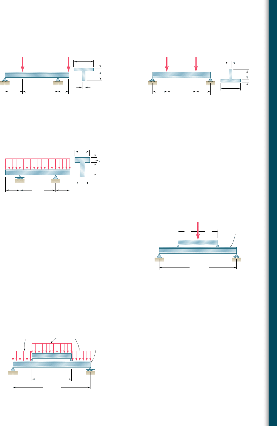
5.85 and 5.86 Determine the largest permissible value of P for the
beam and loading shown, knowing that the allowable normal stress
is 16 ksi in tension and 218 ksi in compression.
B
C
A
D
10 in. 6 in.
20 in.
0.5 in.
0.5 in.
2 in.
4 in.
P P
BC
A
D
16 in.
8 in.
4 in.
2 in.
0.5 in.
0.5 in.
8 in.
PP
Fig. P5.86Fig. P5.85
5.87 Determine the largest permissible distributed load w for the beam
shown, knowing that the allowable normal stress is 180 MPa in
tension and 2130 MPa in compression.
BC
w
A
D
0.2 m 0.2 m
0.5 m
20 mm
20 mm
60 mm
60 mm
Fig. P5.87
5.88 Solve Prob. 5.87, assuming that the cross section of the beam is
reversed, with the flange of the beam resting on the supports at B
and C.
5.89 A 54-kip load is to be supported at the center of the 16-ft span
shown. Knowing that the allowable normal stress for the steel used
is 24 ksi, determine (a) the smallest allowable length l of beam CD
if the W12 3 50 beam AB is not to be overstressed, (b) the most
economical W shape that can be used for beam CD. Neglect the
weight of both beams.
5.90 A uniformly distributed load of 66 kN/m is to be supported over
the 6-m span shown. Knowing that the allowable normal stress for
the steel used is 140 MPa, determine (a) the smallest allowable
length l of beam CD if the W460 3 74 beam AB is not to be
overstressed, (b) the most economical W shape that can be used
for beam CD. Neglect the weight of both beams.
B
A
CD
l/2 l/2
L 16 ft
W12 50
54 kips
Fig. P5.89
B
A
C
D
W460 74
66 kN/m
66 kN/m
l
L 6 m
Fig. P5.90
bee80288_ch05_314-379.indd Page 347 10/27/10 9:55:03 PM user-f499bee80288_ch05_314-379.indd Page 347 10/27/10 9:55:03 PM user-f499 /Volumes/201/MHDQ251/bee80288_disk1of1/0073380288/bee80288_pagefiles/Volumes/201/MHDQ251/bee80288_disk1of1/0073380288/bee80288_pagefiles
Apago PDF Enhancer
348
Analysis and Design of Beams for Bending
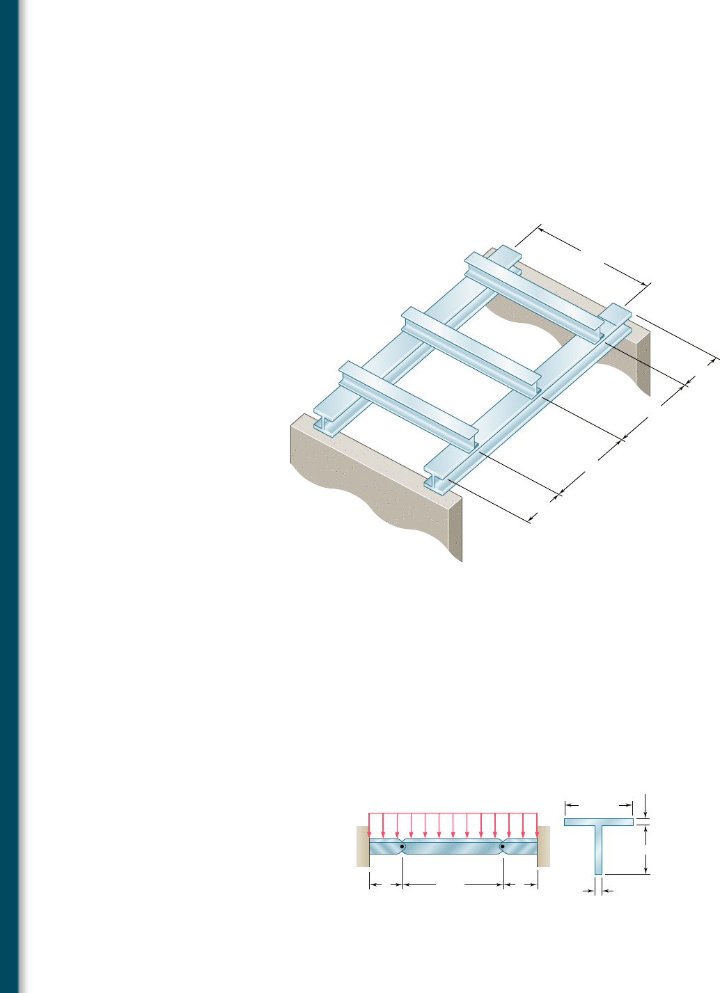
5.91 Each of the three rolled-steel beams shown (numbered 1, 2,
and 3) is to carry a 64-kip load uniformly distributed over the
beam. Each of these beams has a 12-ft span and is to be supported
by the two 24-ft rolled-steel girders AC and BD. Knowing that the
allowable normal stress for the steel used is 24 ksi, select (a) the
most economical S shape for the three beams, (b) the most eco-
nomical W shape for the two girders.
4 ft
4 ft
12 ft
8 ft
1
2
3
8 ft
B
A
C
D
Fig. P5.91
5.92 Beams AB, BC, and CD have the cross section shown and are pin-
connected at B and C. Knowing that the allowable normal stress
is 1110 MPa in tension and 2150 MPa in compression, determine
(a) the largest permissible value of w if beam BC is not to be
overstressed, (b) the corresponding maximum distance a for which
the cantilever beams AB and CD are not overstressed.
BC
w
D
a
7.2 m
12.5 mm
12.5 mm
150 mm
200 mm
A
a
Fig. P5.92
bee80288_ch05_314-379.indd Page 348 10/27/10 9:55:10 PM user-f499bee80288_ch05_314-379.indd Page 348 10/27/10 9:55:10 PM user-f499 /Volumes/201/MHDQ251/bee80288_disk1of1/0073380288/bee80288_pagefiles/Volumes/201/MHDQ251/bee80288_disk1of1/0073380288/bee80288_pagefiles
Apago PDF Enhancer
349
Problems
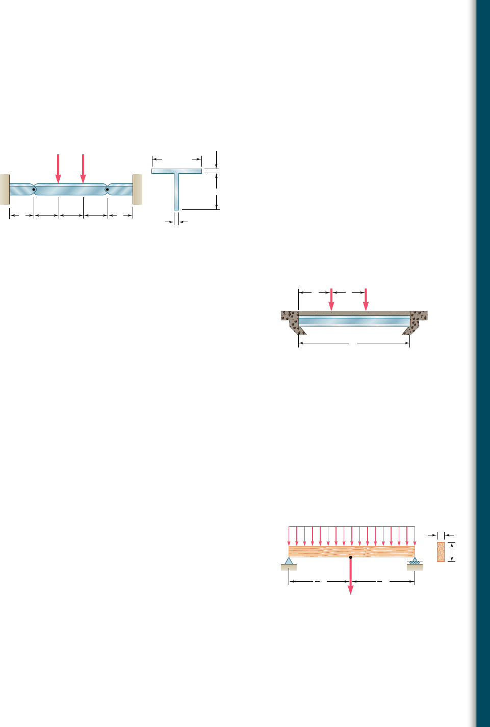
5.93 Beams AB, BC, and CD have the cross section shown and are pin-
connected at B and C. Knowing that the allowable normal stress
is 1110 MPa in tension and 2150 MPa in compression, determine
(a) the largest permissible value of P if beam BC is not to be
overstressed, (b) the corresponding maximum distance a for which
the cantilever beams AB and CD are not overstressed.
PP
BCD
a
2.4 m 2.4 m 2.4 m
12.5 mm
12.5 mm
150 mm
200 mm
A
a
Fig. P5.93
a
AB
x
L
P
2
P
1
Fig. P5.94
*5.94 A bridge of length L 5 48 ft is to be built on a secondary road
whose access to trucks is limited to two-axle vehicles of medium
weight. It will consist of a concrete slab and of simply supported
steel beams with an ultimate strength s
U
5 60 ksi. The combined
weight of the slab and beams can be approximated by a uniformly
distributed load w 5 0.75 kips/ft on each beam. For the purpose
of the design, it is assumed that a truck with axles located at a
distance a 5 14 ft from each other will be driven across the bridge
and that the resulting concentrated loads P
1
and P
2
exerted on
each beam could be as large as 24 kips and 6 kips, respectively.
Determine the most economical wide-flange shape for the beams,
using LRFD with the load factors g
D
5 1.25, g
L
5 1.75 and the
resistance factor f 5 0.9. [Hint: It can be shown that the maxi-
mum value of |M
L
| occurs under the larger load when that load is
located to the left of the center of the beam at a distance equal
to aP
2
y2(P
1
1 P
2
).]
*5.95 Assuming that the front and rear axle loads remain in the same
ratio as for the truck of Prob. 5.94, determine how much heavier
a truck could safely cross the bridge designed in that problem.
*5.96 A roof structure consists of plywood and roofing material sup-
ported by several timber beams of length L 5 16 m. The dead
load carried by each beam, including the estimated weight of the
beam, can be represented by a uniformly distributed load w
D
5
350 N/m. The live load consists of a snow load, represented by a
uniformly distributed load w
L
5 600 N/m, and a 6-kN concen-
trated load P applied at the midpoint C of each beam. Knowing
that the ultimate strength for the timber used is s
U
5 50 MPa and
that the width of each beam is b 5 75 mm, determine the mini-
mum allowable depth h of the beams, using LRFD with the load
factors g
D
5 1.2, g
L
5 1.6 and the resistance factor f 5 0.9.
*5.97 Solve Prob. 5.96, assuming that the 6-kN concentrated load P
applied to each beam is replaced by 3-kN concentrated loads P
1
and P
2
applied at a distance of 4 m from each end of the beams.
P
w
D
w
L
C
b
h
AB
L
1
2
L
1
2
Fig. P5.96
bee80288_ch05_314-379.indd Page 349 10/27/10 9:55:15 PM user-f499bee80288_ch05_314-379.indd Page 349 10/27/10 9:55:15 PM user-f499 /Volumes/201/MHDQ251/bee80288_disk1of1/0073380288/bee80288_pagefiles/Volumes/201/MHDQ251/bee80288_disk1of1/0073380288/bee80288_pagefiles
Apago PDF Enhancer
350
Analysis and Design of Beams for Bending
*5.5 USING SINGULARITY FUNCTIONS TO
DETERMINE SHEAR AND BENDING MOMENT
IN A BEAM
Reviewing the work done in the preceding sections, we note that the
shear and bending moment could only rarely be described by single
analytical functions. In the case of the cantilever beam of Example
5.02 (Fig. 5.9), which supported a uniformly distributed load w, the
shear and bending moment could be represented by single analytical
functions, namely, V 5 2wx and M 52
1
2
wx
2
; this was due to the
fact that no discontinuity existed in the loading of the beam. On the
other hand, in the case of the simply supported beam of Exam-
ple 5.01, which was loaded only at its midpoint C, the load P applied
at C represented a singularity in the beam loading. This singularity
resulted in discontinuities in the shear and bending moment and
required the use of different analytical functions to represent V and
M in the portions of beam located, respectively, to the left and to
the right of point C. In Sample Prob. 5.2, the beam had to be divided
into three portions, in each of which different functions were used
to represent the shear and the bending moment. This situation led
us to rely on the graphical representation of the functions V and M
provided by the shear and bending-moment diagrams and, later in
Sec. 5.3, on a graphical method of integration to determine V and
M from the distributed load w.
The purpose of this section is to show how the use of singular-
ity functions makes it possible to represent the shear V and the
bending moment M by single mathematical expressions.
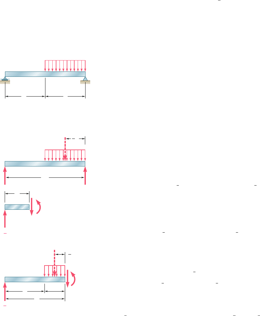
Consider the simply supported beam AB, of length 2a, which
carries a uniformly distributed load w
0
extending from its midpoint
C to its right-hand support B (Fig. 5.15). We first draw the free-body
diagram of the entire beam (Fig. 5.16a); replacing the distributed
load by an equivalent concentrated load and, summing moments
about B, we write
1
l
o
M
B
5 0:
1
w
0
a
21
1
2
a
2
2 R
A
1
2a
2
5 0 R
A
5
1
4
w
0
a
Next we cut the beam at a point D between A and C. From the
free-body diagram of AD (Fig. 5.16b) we conclude that, over the
interval 0 , x , a, the shear and bending moment are expressed,
respectively, by the functions
V
1
1
x
2
5
1
4
w
0
a and M
1
1
x
2
5
1
4
w
0
ax
Cutting, now, the beam at a point E between C and B, we draw the
free-body diagram of portion AE (Fig. 5.16c). Replacing the distrib-
uted load by an equivalent concentrated load, we write
1x oF
y
5 0:
1
4
w
0
a 2 w
0
1
x 2 a
2
2 V
2
5 0
1
l
o
M
E
5 0: 2
1
4
w
0
ax 1 w
0
1
x 2 a
23
1
2
1
x 2 a
24
1 M
2
5 0
and conclude that, over the interval a , x , 2a, the shear and bend-
ing moment are expressed, respectively, by the functions
V
2
1
x
2
5
1
4
w
0
a 2 w
0
1
x 2 a
2
and M
2
1
x
2
5
1
4
w
0
ax 2
1
2
w
0
1
x 2 a
2
2
B
C
w
0
A
aa
Fig. 5.15
B
R
B
M
1
V
1
R
A
C
D
x
A
w
0
w
0
a
A
2a
a
1
2
(a)
M
2
V
2
C
E
w
0
(x a)
A
x
a
(x a)
x a
1
2
(c)
(b)
R
A
w
0
a
1
4
R
A
w
0
a
1
4
Fig. 5.16
bee80288_ch05_314-379.indd Page 350 10/27/10 9:55:22 PM user-f499bee80288_ch05_314-379.indd Page 350 10/27/10 9:55:22 PM user-f499 /Volumes/201/MHDQ251/bee80288_disk1of1/0073380288/bee80288_pagefiles/Volumes/201/MHDQ251/bee80288_disk1of1/0073380288/bee80288_pagefiles

Apago PDF Enhancer
351
As we pointed out earlier in this section, the fact that the shear
and bending moment are represented by different functions of x,
depending upon whether x is smaller or larger than a, is due to the
discontinuity in the loading of the beam. However, the functions
V
1
(x) and V
2
(x) can be represented by the single expression
V1x25
1
4
w
0
a 2 w
0
H
x 2 a
I
(5.11)
if we specify that the second term should be included in our com-
putations when x $ a and ignored when x , a. In other words, the
brackets
H
I
should be replaced by ordinary parentheses ( ) when
x $ a and by zero when x , a. With the same convention, the bending
moment can be represented at any point of the beam by the single
expression
M1x25
1
4
w
0
ax 2
1
2
w
0
H
x 2 a
I
2
(5.12)
From the convention we have adopted, it follows that brackets
H
I
can be differentiated or integrated as ordinary parentheses.
Instead of calculating the bending moment from free-body diagrams,
we could have used the method indicated in Sec. 5.3 and integrated
the expression obtained for V(x):
M1x22 M1025
#
x
0
V1x2 dx 5
#
x
0
1
4
w
0
a dx 2
#
x
0
w
0
Hx 2 aI dx
After integration, and observing that M(0) 5 0, we obtain as before
M1x25
1
4
w
0
ax 2
1
2
w
0
H
x 2 a
I
2
Furthermore, using the same convention again, we note that
the distributed load at any point of the beam can be expressed as
w1x25 w
0
H
x 2 a
I
0
(5.13)
Indeed, the brackets should be replaced by zero for x , a and
by parentheses for x $ a; we thus check that w(x) 5 0 for x , a
and, defining the zero power of any number as unity, that
H
x 2 a
I
0
5 1x 2 a2
0
5 1 and w(x) 5 w
0
for x $ a. From Sec. 5.3 we
recall that the shear could have been obtained by integrating the
function 2w(x). Observing that V 5
1
4
w
0
a for x 5 0, we write
V1x22 V10252
#
x
0
w1x2 dx 52
#
x
0
w
0
Hx 2 aI
0
dx
V1x22
1
4
w
0
a 52w
0
H
x 2 a
I
1
Solving for V(x) and dropping the exponent 1, we obtain again
V1x25
1
4
w
0
a 2 w
0
H
x 2 a
I
The expressions
H
x 2 a
I
0
,
H
x 2 a
I
,
H
x 2 a
I
2
are called singularity
functions. By definition, we have, for n $ 0,
Hx 2 aI
n
5
e
1x 2 a2
n
0
when x $ a
when
x
, a
(5.14)
5.5 Using Singularity Functions to Determine
Shear and Bending Moment in a Beam
bee80288_ch05_314-379.indd Page 351 10/27/10 9:55:23 PM user-f499bee80288_ch05_314-379.indd Page 351 10/27/10 9:55:23 PM user-f499 /Volumes/201/MHDQ251/bee80288_disk1of1/0073380288/bee80288_pagefiles/Volumes/201/MHDQ251/bee80288_disk1of1/0073380288/bee80288_pagefiles
Apago PDF Enhancer
352
Analysis and Design of Beams for Bending
We also note that whenever the quantity between brackets is positive
or zero, the brackets should be replaced by ordinary parentheses, and
whenever that quantity is negative, the bracket itself is equal to zero.
0
(a) n 0
x a
0
ax0
(b) n 1
x a
1
ax0
(c) n 2
x a
2
ax
Fig. 5.17 Singularity functions.
†Since (x 2 a)
0
is discontinuous at x 2 a, it can be argued that this function should be
left undefined for x 5 a or that it should be assigned both of the values 0 and 1 for x 5 a.
However, defining (x 2 a)
0
as equal to 1 when x 5 a, as stated in (Eq. 5.15), has the
advantage of being unambiguous and, thus, readily applicable to computer programming
(cf. page 348).
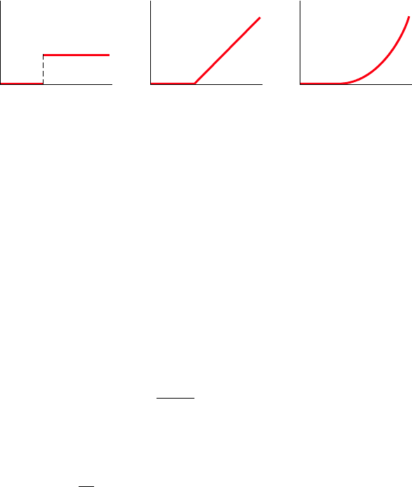
The three singularity functions corresponding respectively to
n 5 0, n 5 1, and n 5 2 have been plotted in Fig. 5.17. We note that
the function
H
x 2 a
I
0
is discontinuous at x 5 a and is in the shape
of a “step.” For that reason it is referred to as the step function.
According to (5.14), and with the zero power of any number defined
as unity, we have†
Hx 2 aI
0
5
e
1
0
when x $ a
when
x
, a
(5.15)
It follows from the definition of singularity functions that
#
Hx 2 aI
n
dx 5
1
n 1 1
Hx 2 aI
n11
for n $ 0 (5.16)
and
d
d
x
Hx 2 aI
n
5 nHx 2 aI
n21
for n $ 1
(5.17)
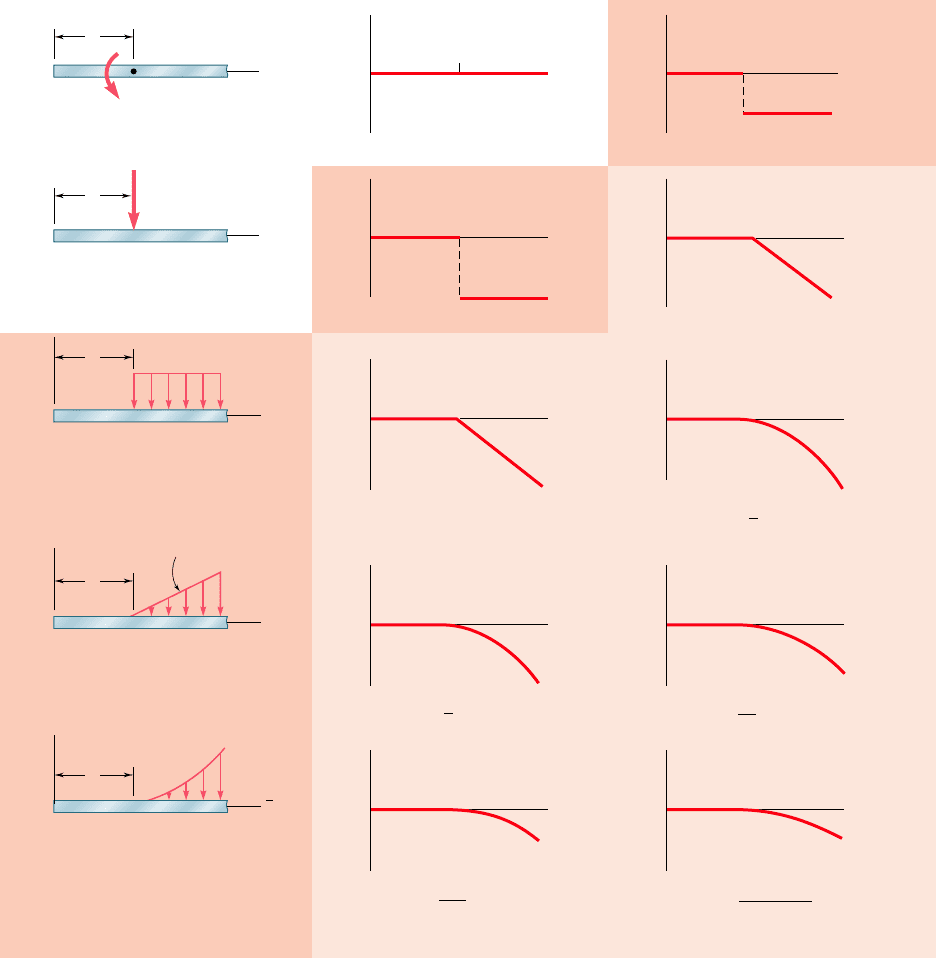
Most of the beam loadings encountered in engineering practice
can be broken down into the basic loadings shown in Fig. 5.18.
Whenever applicable, the corresponding functions w(x), V(x), and
M(x) have been expressed in terms of singularity functions and plot-
ted against a color background. A heavier color background was used
to indicate for each loading the expression that is most easily derived
or remembered and from which the other functions can be obtained
by integration.
bee80288_ch05_314-379.indd Page 352 10/27/10 9:55:27 PM user-f499bee80288_ch05_314-379.indd Page 352 10/27/10 9:55:27 PM user-f499 /Volumes/201/MHDQ251/bee80288_disk1of1/0073380288/bee80288_pagefiles/Volumes/201/MHDQ251/bee80288_disk1of1/0073380288/bee80288_pagefiles
Apago PDF Enhancer
353
5.5 Using Singularity Functions to Determine
Shear and Bending Moment in a Beam
a
a
x
xO
O
V
M
0
P
Loading Shear Bending Moment
(a)
a
x
O
(b)
a
x
O
w
(c) w (x) w
0
x a
0
V (x) P
x a
0
(d) w (x) k
x a
1
(e) w (x) k
x a
n
Slope k
w
0
a
x
O
w
a
x
O
w
a
x
O
V
P
M (x) M
0
x a
0
a
x
O
M
M
0
V (x) w
0
x a
1
a
x
O
V
M (x) P
x a
1
a
x
O
M
V (x)
x a
2
a
x
O
V
k
2
a
x
O
M
M (x) w
0
x a
2
a
x
O
M
1
2
M (x) x a
3
k
2
?
3
M (x) x a
n 2
k
(n 1) (n 2)
V (x)
x a
n 1
k
n 1
a
x
O
V
a
x
O
M
Fig. 5.18 Basic loadings and corresponding shears and bending moments expressed in terms of singularity functions.
After a given beam loading has been broken down into the
basic loadings of Fig. 5.18, the functions V(x) and M(x) representing
the shear and bending moment at any point of the beam can be
obtained by adding the corresponding functions associated with each
of the basic loadings and reactions. Since all the distributed loadings
shown in Fig. 5.18 are open-ended to the right, a distributed loading
bee80288_ch05_314-379.indd Page 353 11/12/10 7:31:40 PM user-f499bee80288_ch05_314-379.indd Page 353 11/12/10 7:31:40 PM user-f499 /Users/user-f499/Desktop/Temp Work/Don't Delete Job/MHDQ251:Beer:201/ch05/Users/user-f499/Desktop/Temp Work/Don't Delete Job/MHDQ251:Beer:201/ch05
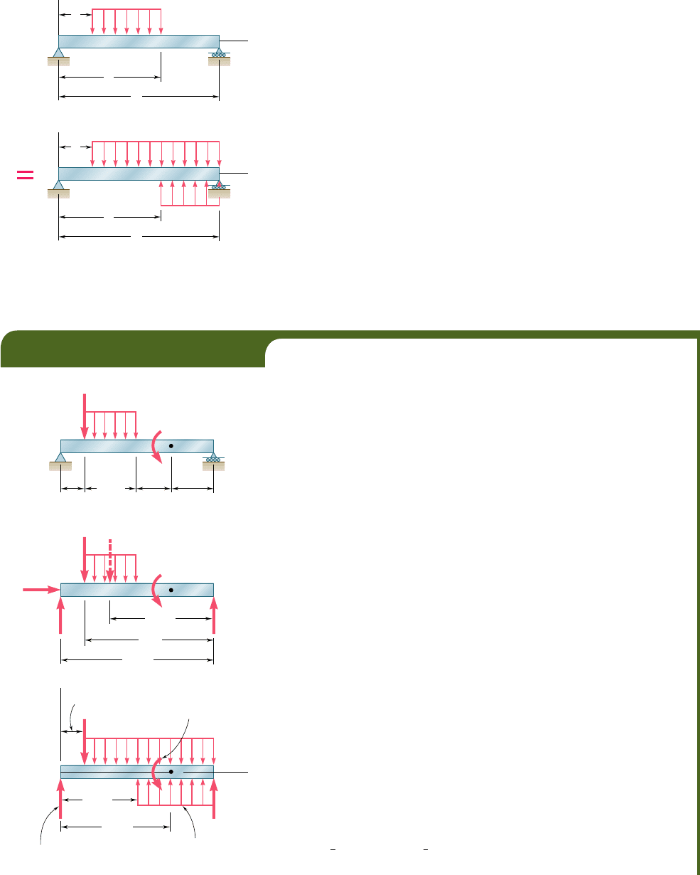
Apago PDF Enhancer
that does not extend to the right end of the beam or that is discon-
tinuous should be replaced as shown in Fig. 5.19 by an equivalent
combination of open-ended loadings. (See also Example 5.05 and
Sample Prob. 5.9.)
As you will see in Sec. 9.6, the use of singularity functions also
greatly simplifies the determination of beam deflections. It was in
connection with that problem that the approach used in this section
was first suggested in 1862 by the German mathematician A. Clebsch
(1833–1872). However, the British mathematician and engineer
W. H. Macaulay (1853–1936) is usually given credit for introducing
the singularity functions in the form used here, and the brackets
H
I
are generally referred to as Macaulay’s brackets.†
x
O
w
w
0
b
L
a
x
O
w
w
0
w
0
b
L
a
w(x) w
0
x a
0
w
0
x b
0
Fig. 5.19 Use of open-ended loadings to
create a closed-ended loading.
†W. H. Macaulay, “Note on the Deflection of Beams,” Messenger of Mathematics, vol. 48,
pp. 129–130, 1919.
B
E
DC
P 1.2 kN
A
w
0
1.5 kN/m
w
0
1.5 kN/m
w
0
1.5 kN/m
w
M
0
1.44 kN
?
m
0.6 m 0.8 m 1.0 m
1.2 m
(a)
B
B
DC
P 1.2 kN
A
A
x
A
y
A
y
2.6 kN
1.8 kN
M
0
1.44 kN
?
m
3.6 m
0.6 m
3 m
2.4 m
(b)
B
x
B
C
D
P 1.2 kN
A
M
0
1.44 kN
?
m
2.6 m
1.8 m
(c)
E
E
Fig. 5.20
For the beam and loading shown (Fig. 5.20a) and using singularity func-
tions, express the shear and bending moment as functions of the distance
x from the support at A.
We first determine the reaction at A by drawing the free-body
diagram of the beam (Fig. 5.20b) and writing
y
1
oF
x
5 0:
A
x
5
0
1
l
o
M
B
5 0: 2A
y
1
3.6 m
2
1
1
1.2 kN
21
3 m
2
1
1
1.8 kN
21
2.4 m
2
1 1.44 kN ? m 5 0
A
y
5 2.60
k
N
Next, we replace the given distributed loading by two equivalent
open-ended loadings (Fig. 5.20c) and express the distributed load w(x) as
the sum of the corresponding step functions:
w
1x251w
0
H
x 2 0.6
I
0
2 w
0
H
x 2 1.8
I
0
The function V(x) is obtained by integrating w(x), reversing the 1
and 2 signs, and adding to the result the constants A
y
and 2P
H
x 2 0.6
I
0
representing the respective contributions to the shear of the reaction at
A and of the concentrated load. (No other constant of integration is
required.) Since the concentrated couple does not directly affect the
shear, it should be ignored in this computation. We write
V1x252w
0
H
x 2 0.6
I
1
1 w
0
H
x 2 1.8
I
1
1 A
y
2 P
H
x 2 0.6
I
0
In a similar way, the function M(x) is obtained by integrating V(x) and
adding to the result the constant 2M
0
H
x 2 2.6
I
0
representing the contri-
bution of the concentrated couple to the bending moment. We have
M1x252
1
2
w
0
H
x 2 0.6
I
2
1
1
2
w
0
H
x 2 1.8
I
2
1 A
y
x 2 P
H
x 2 0.6
I
1
2 M
0
H
x 2 2.6
I
0
EXAMPLE 5.05
354
bee80288_ch05_314-379.indd Page 354 11/12/10 7:31:42 PM user-f499bee80288_ch05_314-379.indd Page 354 11/12/10 7:31:42 PM user-f499 /Users/user-f499/Desktop/Temp Work/Don't Delete Job/MHDQ251:Beer:201/ch05/Users/user-f499/Desktop/Temp Work/Don't Delete Job/MHDQ251:Beer:201/ch05

Apago PDF Enhancer
Substituting the numerical values of the reaction and loads into the
expressions obtained for V(x) and M(x) and being careful not to compute
any product or expand any square involving a bracket, we obtain the fol-
lowing expressions for the shear and bending moment at any point of the
beam:
V1x2521.5
H
x 2 0.6
I
1
1 1.5
H
x 2 1.8
I
1
1 2.6 2 1.2
H
x 2 0.6
I
0
M1x2520.75
H
x 2 0.6
I
2
1 0.75
H
x 2 1.8
I
2
1 2.6x 2 1.2
H
x 2 0.6
I
1
2 1.44
H
x 2 2.6
I
0
355
EXAMPLE 5.06
For the beam and loading of Example 5.05, determine the numerical
values of the shear and bending moment at the midpoint D.
Making x 5 1.8 m in the expressions found for V(x) and M(x) in
Example 5.05, we obtain
V11.82521.5
H
1.2
I
1
1 1.5
H
0
I
1
1 2.6 2 1.2
H
1.2
I
0
M11.82520.75
H
1.2
I
2
1 0.75
H
0
I
2
1 2.611.822 1.2
H
1.2
I
1
2 1.44
H
20.8
I
0
Recalling that whenever a quantity between brackets is positive or zero,
the brackets should be replaced by ordinary parentheses, and whenever
the quantity is negative, the bracket itself is equal to zero, we write
V
1
1.8
2
521.5
1
1.2
2
1
1 1.5
1
0
2
1
1 2.6 2 1.2
1
1.2
2
0
521.5
1
1.2
2
1 1.5
1
0
2
1 2.6 2 1.2
1
1
2
52
1.8
1
0
1
2.6
2
1.2
V
1
1.8
2
520.4 kN
and
M
1
1.8
2
520.75
1
1.2
2
2
1 0.75
1
0
2
2
1 2.6
1
1.8
2
2 1.2
1
1.2
2
1
2 1.44
1
0
2
52
1.08
1
0
1
4.68
2
1.44
2
0
M
1
1.8
2
512.16 kN ? m
Application to Computer Programming. Singularity functions
are particularly well suited to the use of computers. First we note
that the step function
H
x 2 a
I
0
, which will be represented by the
symbol STP, can be defined by an IF/THEN/ELSE statement as
being equal to 1 for X $ A and to 0 otherwise. Any other singularity
function
H
x 2 a
I
n
, with n $ 1, can then be expressed as the product
of the ordinary algebraic function
1
x 2 a
2
n
and the step function
H
x 2 a
I
0
.
When k different singularity functions are involved, such as
H
x 2 a
i
I
n
, where i 5 1, 2, . . ., k, then the corresponding step functions
STP(I), where I 5 1, 2, . . ., K, can be defined by a loop containing
a single IF/THEN/ELSE statement.
bee80288_ch05_314-379.indd Page 355 11/16/10 6:42:43 PM user-f499bee80288_ch05_314-379.indd Page 355 11/16/10 6:42:43 PM user-f499 /Volumes/201/MHDQ251/bee80288_disk1of1/0073380288/bee80288_pagefiles/Volumes/201/MHDQ251/bee80288_disk1of1/0073380288/bee80288_pagefiles
Apago PDF Enhancer
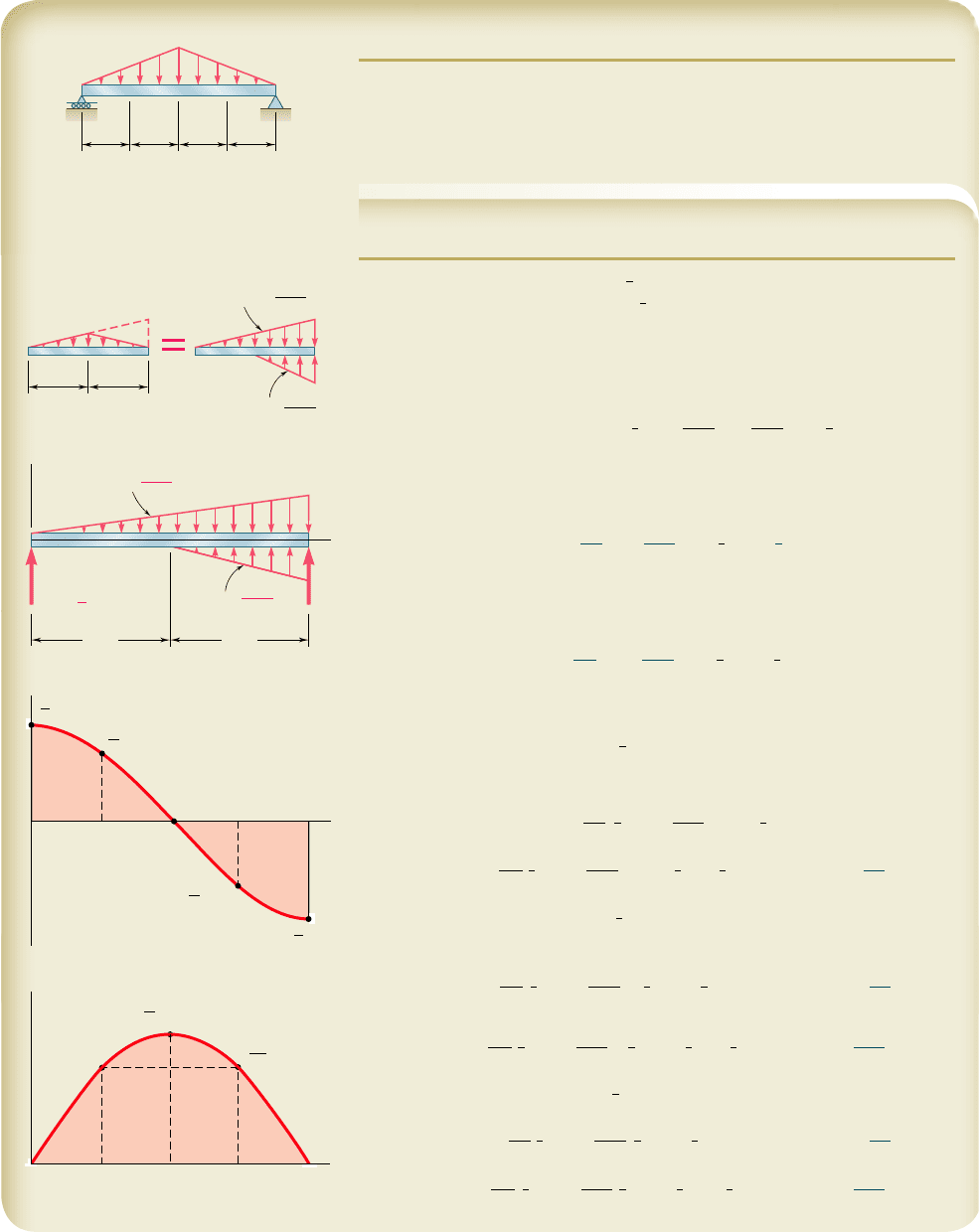
SAMPLE PROBLEM 5.9
For the beam and loading shown, determine (a) the equations de ning the shear
and bending moment at any point, (b) the shear and bending moment at points
C, D, and E.
SOLUTION
Reactions. The total load is
1
2
w
0
L; because of symmetry, each reaction
is equal to half that value, namely,
1
4
w
0
L.
Distributed Load. The given distributed loading is replaced by two
equivalent open-ended loadings as shown. Using a singularity function to
express the second loading, we write
w
1x25 k
1
x 1 k
2
Hx 2
1
2
LI5
2
w
0
L
x 2
4
w
0
L
Hx 2
1
2
LI
(1)
a. Equations for Shear and Bending Moment. We obtain
V1x2
by
integrating (1), changing the signs, and adding a constant equal to
R
A
:
V1x252
w
0
L
x
2
1
2
w
0
L
Hx 2
1
2
LI
2
1
1
4
w
0
L
(2)
◀
We obtain M(x) by integrating (2); since there is no concentrated couple,
no constant of integration is needed:
M1x252
w
0
3L
x
3
1
2
w
0
3L
Hx 2
1
2
LI
3
1
1
4
w
0
Lx
(3)
◀
b. Shear and Bending Moment at C, D, and E
At Point C: Making
x
5
1
2
L in Eqs. (2) and (3) and recalling that
whenever a quantity between brackets is positive or zero, the brackets may
be replaced by parentheses, we have
V
C
52
w
0
L
1
1
2
L2
2
1
2
w
0
L
H0I
2
1
1
4
w
0
L
V
C
5
0
◀
M
C
52
w
0
3L
1
1
2
L2
3
1
2
w
0
3L
H0I
3
1
1
4
w
0
L1
1
2
L2
M
C
5
1
1
2
w
0
L
2
◀
At Point D: Making
x
5
1
4
L in Eqs. (2) and (3) and recalling that a
bracket containing a negative quantity is equal to zero, we write
V
D
52
w
0
L
1
1
4
L2
2
1
2
w
0
L
H2
1
4
LI
2
1
1
4
w
0
L
V
D
5
3
16
w
0
L
◀
M
D
52
w
0
3L
1
1
4
L2
3
1
2
w
0
3L
H2
1
4
LI
3
1
1
4
w
0
L1
1
4
L2
M
D
5
11
19
2
w
0
L
2
◀
At Point E: Making
x
5
3
4
L in Eqs. (2) and (3), we have
V
E
52
w
0
L
1
3
4
L2
2
1
2
w
0
L
H
1
4
LI
2
1
1
4
w
0
L
V
E
52
3
16
w
0
L
◀
M
E
52
w
0
3L
1
3
4
L2
3
1
2
w
0
3L
H
1
4
LI
3
1
1
4
w
0
L1
3
4
L2
M
E
5
11
19
2
w
0
L
2
◀
B
w
0
A
D
L/4 L/4 L/4 L/4
CE
w
0
2w
0
L/2 L/2
CC
A
B
2w
0
2w
0
2w
0
L
A
B
Slope
4w
0
L
Slope
L/2
x
x
x
L/2
C
CE
D
B
w
0
L
R
B
R
A
w
0
L
2w
0
L
A
V
A
M
CEDBA
w
B
k
1
4w
0
L
k
2
1
4
3
16
w
0
L
3
16
11
192
w
0
L
2
1
12
w
0
L
2
w
0
L
1
4
w
0
L
1
4
356
bee80288_ch05_314-379.indd Page 356 11/12/10 7:31:49 PM user-f499bee80288_ch05_314-379.indd Page 356 11/12/10 7:31:49 PM user-f499 /Users/user-f499/Desktop/Temp Work/Don't Delete Job/MHDQ251:Beer:201/ch05/Users/user-f499/Desktop/Temp Work/Don't Delete Job/MHDQ251:Beer:201/ch05
