Beer F.P., Johnston E.R., DeWolf J.T., Mazurek D.F. Mechanics of Materials
Подождите немного. Документ загружается.

Apago PDF Enhancer
367
Problems
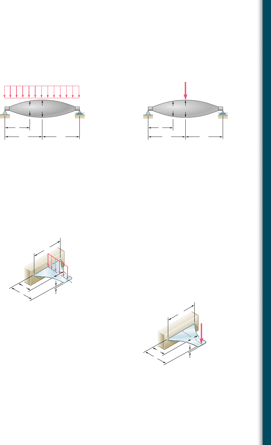
5.136 and 5.137 A machine element of cast aluminum and in the
shape of a solid of revolution of variable diameter d is being designed
to support the load shown. Knowing that the machine element is
to be of constant strength, express d in terms of x, L, and d
0
.
w
AB
C
x
L/2 L/2
dd
0
Fig. P5.136
P
AB
C
x
L/2 L/2
dd
0
Fig. P5.137
5.138 A cantilever beam AB consisting of a steel plate of uniform depth h
and variable width b is to support the distributed load w along its
centerline AB. (a) Knowing that the beam is to be of constant
strength, express b in terms of x, L, and b
0
. (b) Determine the maxi-
mum allowable value of w if L 5 15 in., b
0
5 8 in., h 5 0.75 in.,
and s
all
5 24 ksi.
x
L
h
A
B
b
0
w
b
Fig. P5.138
x
L
h
A
B
b
0
b
P
Fig. P5.139
5.139 A cantilever beam AB consisting of a steel plate of uniform depth
h and variable width b is to support the concentrated load P at
point A. (a) Knowing that the beam is to be of constant strength,
express b in terms of x, L, and b
0
. (b) Determine the smallest
allowable value of h if L 5 300 mm, b
0
5 375 mm, P 5 14.4 kN,
and s
all
5 160 MPa.
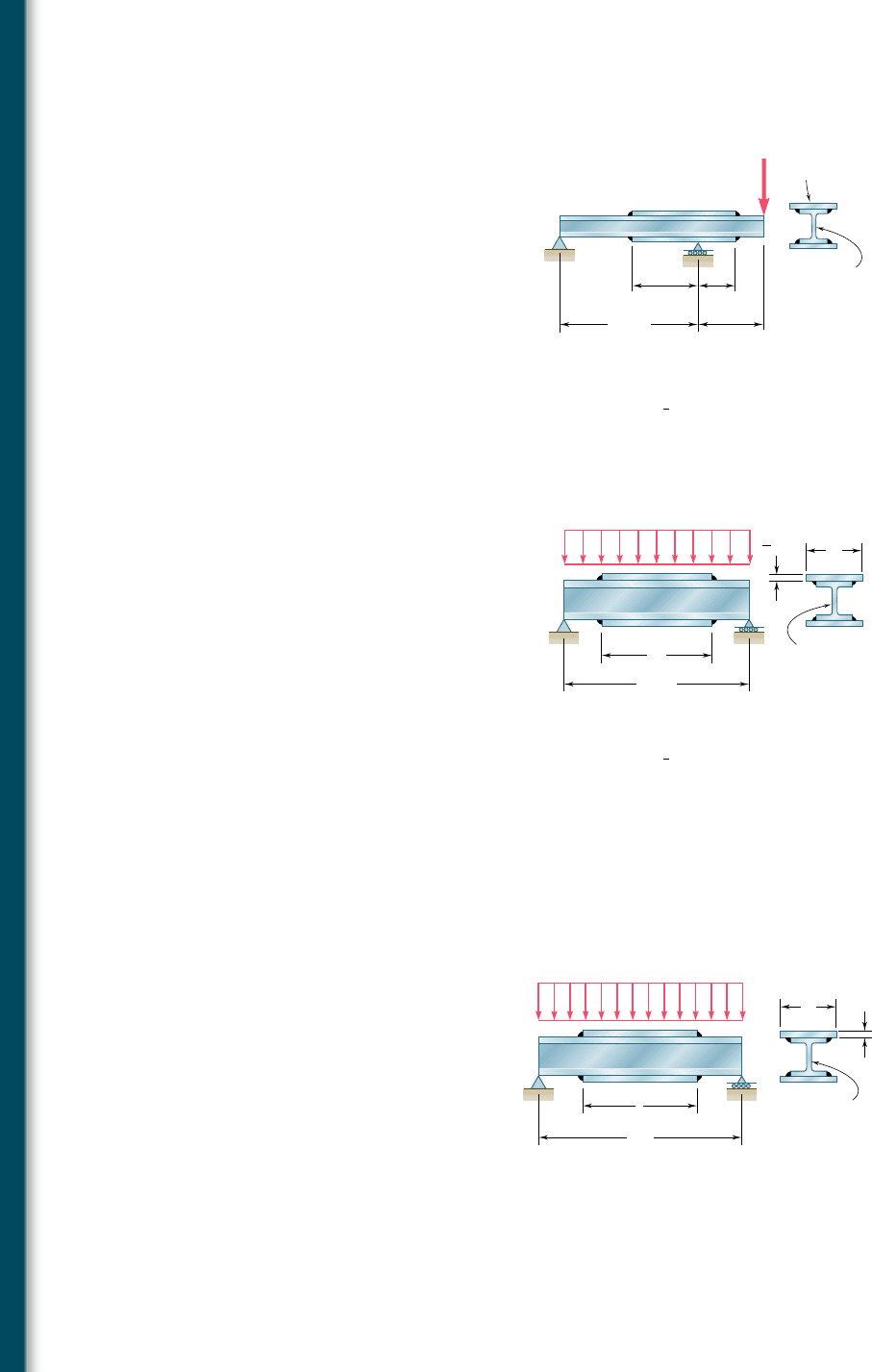
5.140 Assuming that the length and width of the cover plates used with
the beam of Sample Prob. 5.12 are, respectively, l 5 4 m and b 5
285 mm, and recalling that the thickness of each plate is 16 mm,
determine the maximum normal stress on a transverse section
(a) through the center of the beam, (b) just to the left of D.
bee80288_ch05_314-379.indd Page 367 10/27/10 9:58:50 PM user-f499bee80288_ch05_314-379.indd Page 367 10/27/10 9:58:50 PM user-f499 /Volumes/201/MHDQ251/bee80288_disk1of1/0073380288/bee80288_pagefiles/Volumes/201/MHDQ251/bee80288_disk1of1/0073380288/bee80288_pagefiles
Apago PDF Enhancer
368
Analysis and Design of Beams for Bending
5.141 Knowing that s
all
5 150 MPa, determine the largest concentrated
load P that can be applied at end E of the beam shown.
E
C
A
B
D
P
W410 ⫻ 85
18 ⫻ 220 mm
2.25 m 1.25 m
2.2 m
4.8 m
Fig. P5.141
5.142 Two cover plates, each
5
8
in. thick, are welded to a W30 3 99 beam
as shown. Knowing that l 5 9 ft and b 5 12 in., determine the
maximum normal stress on a transverse section (a) through the
center of the beam, (b) just to the left of D.
B
b
E
D
A
W30 × 99
16 ft
30 kips/ft
in.
5
8
l
Fig. P5.142 and P5.143
B
b
7.5 mm
ED
A
l
W460 × 74
8 m
40 kN/m
Fig. P5.144 and P5.145
5.143 Two cover plates, each
5
8
in. thick, are welded to a W30 3 99 beam
as shown. Knowing that s
all
5 22 ksi for both the beam and the
plates, determine the required value of (a) the length of the plates,
(b) the width of the plates.
5.144 Two cover plates, each 7.5 mm thick, are welded to a W460 3 74
beam as shown. Knowing that l 5 5 m and b 5 200 mm, determine
the maximum normal stress on a transverse section (a) through the
center of the beam, (b) just to the left of D.
5.145 Two cover plates, each 7.5 mm thick, are welded to a W460 3 74
beam as shown. Knowing that s
all
5 150 MPa for both the beam
and the plates, determine the required value of (a) the length of
the plates, (b) the width of the plates.
bee80288_ch05_314-379.indd Page 368 10/27/10 9:58:59 PM user-f499bee80288_ch05_314-379.indd Page 368 10/27/10 9:58:59 PM user-f499 /Volumes/201/MHDQ251/bee80288_disk1of1/0073380288/bee80288_pagefiles/Volumes/201/MHDQ251/bee80288_disk1of1/0073380288/bee80288_pagefiles
Apago PDF Enhancer
369
Problems
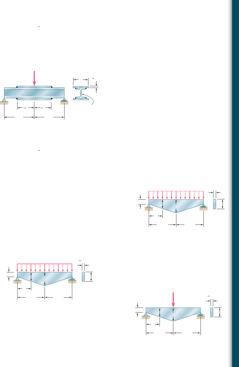
5.147 Two cover plates, each
1
2
in. thick, are welded to a W27 3 84 beam
as shown. Knowing that s
all
5 24 ksi for both the beam and the
plates, determine the required value of (a) the length of the plates,
(b) the width of the plates.
5.148 For the tapered beam shown, determine (a) the transverse section
in which the maximum normal stress occurs, (b) the largest distrib-
uted load w that can be applied, knowing that s
all
5 140 MPa.
5.149 For the tapered beam shown, knowing that w 5 160 kN/m, deter-
mine (a) the transverse section in which the maximum normal
stress occurs, (b) the corresponding value of the normal stress.
5.150 For the tapered beam shown, determine (a) the transverse section
in which the maximum normal stress occurs, (b) the largest distrib-
uted load w that can be applied, knowing that s
all
5 24 ksi.
in.
1
2
B
b
EDC
A
l
W27 × 84
9 ft
160 kips
1
2
l
1
2
9 ft
Fig. P5.146 and P5.147
5.146 Two cover plates, each
1
2
in. thick, are welded to a W27 3 84 beam
as shown. Knowing that l 5 10 ft and b 5 10.5 in., determine the
maximum normal stress on a transverse section (a) through the
center of the beam, (b) just to the left of D.
C
x
0.6 m
120 mm
AB
h
h
0.6 m
300 mm
w
20 mm
Fig. P5.148 and P5.149
AB
x
30 in.
4 in.
h
h
30 in.
in.
3
4
8 in.
C
w
Fig. P5.150
5.151 For the tapered beam shown, determine (a) the transverse section
in which the maximum normal stress occurs, (b) the largest con-
centrated load P that can be applied, knowing that s
all
5 24 ksi.
x
30 in.
4 in.
ABC
h
h
30 in.
P
8 in.
in.
3
4
Fig. P5.151
bee80288_ch05_314-379.indd Page 369 10/27/10 9:59:06 PM user-f499bee80288_ch05_314-379.indd Page 369 10/27/10 9:59:06 PM user-f499 /Volumes/201/MHDQ251/bee80288_disk1of1/0073380288/bee80288_pagefiles/Volumes/201/MHDQ251/bee80288_disk1of1/0073380288/bee80288_pagefiles
Apago PDF Enhancer
370
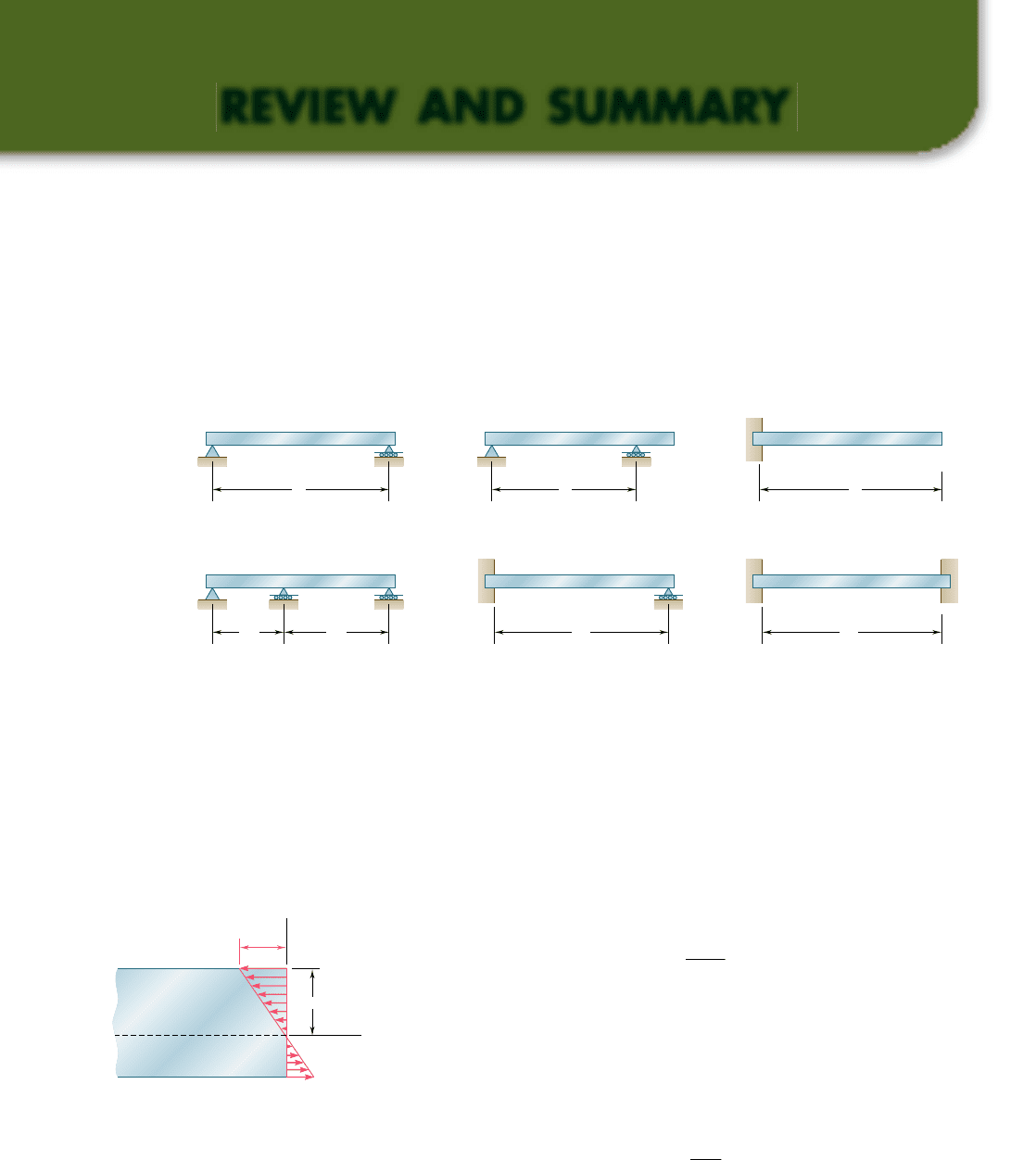
This chapter was devoted to the analysis and design of beams under
transverse loadings. Such loadings can consist of concentrated loads
or distributed loads and the beams themselves are classified accord-
ing to the way they are supported (Fig. 5.22). Only statically deter-
minate beams were considered in this chapter, where all support
reactions can be determined by statics. The analysis of statically inde-
terminate beams is postponed until Chap. 9.
Considerations for the design of
prismatic beams
Considerations for the design of
prismatic beams
L
(a) Simply supported beam
Statically
Determinate
Beams
Statically
Indeterminate
Beams
L
2
L
1
(d) Continuous beam
L
(b) Overhanging beam
L
Beam fixed at one end
and simply supported
at the other end
(e)
L
(c) Cantilever beam
L
( f ) Fixed beam
Fig. 5.22
y
c
m
x
Neutral surface
Fig. 5.23
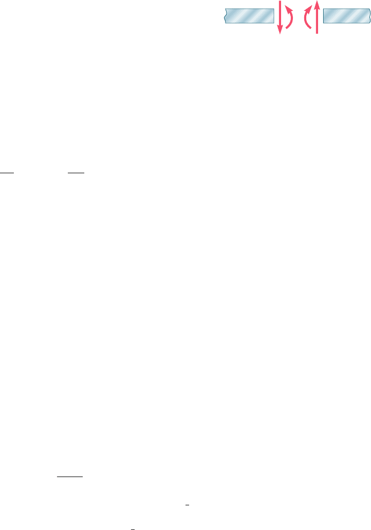
While transverse loadings cause both bending and shear in a beam,
the normal stresses caused by bending are the dominant criterion in
the design of a beam for strength [Sec. 5.1]. Therefore, this chapter
dealt only with the determination of the normal stresses in a beam,
the effect of shearing stresses being examined in the next one.
We recalled from Sec. 4.4 the flexure formula for the determi-
nation of the maximum value s
m
of the normal stress in a given
section of the beam,
s
m
5
0
M
0
c
I
(5.1)
where I is the moment of inertia of the cross section with respect to a
centroidal axis perpendicular to the plane of the bending couple M and
c is the maximum distance from the neutral surface (Fig. 5.23). We
also recalled from Sec. 4.4 that, introducing the elastic section modulus
S 5 Iyc of the beam, the maximum value s
m
of the normal stress in
the section can be expressed as
s
m
5
0
M
0
S
(5.3)
It follows from Eq. (5.1) that the maximum normal stress occurs in
the section where |M| is largest, at the point farthest from the neutral
Normal stresses due to bending
Shear and bending-moment
diagrams
REVIEW AND SUMMARY
bee80288_ch05_314-379.indd Page 370 10/27/10 9:59:16 PM user-f499bee80288_ch05_314-379.indd Page 370 10/27/10 9:59:16 PM user-f499 /Volumes/201/MHDQ251/bee80288_disk1of1/0073380288/bee80288_pagefiles/Volumes/201/MHDQ251/bee80288_disk1of1/0073380288/bee80288_pagefiles
Apago PDF Enhancer
371
axis. The determination of the maximum value of |M| and of the critical
section of the beam in which it occurs is greatly simplified if we draw
a shear diagram and a bending-moment diagram. These diagrams rep-
resent, respectively, the variation of the shear and of the bending
moment along the beam and were obtained by determining the values
of V and M at selected points of the beam [Sec. 5.2]. These values
were found by passing a section through the point where they were
to be determined and drawing the free-body diagram of either of the
portions of beam obtained in this fashion. To avoid any confusion
regarding the sense of the shearing force V and of the bending couple
M (which act in opposite sense on the two portions of the beam), we
followed the sign convention adopted earlier in the text as illustrated
in Fig. 5.24 [Examples 5.01 and 5.02, Sample Probs. 5.1 and 5.2].
The construction of the shear and bending-moment diagrams is
facilitated if the following relations are taken into account [Sec. 5.3].
Denoting by w the distributed load per unit length (assumed positive
if directed downward), we wrote
d
V
d
x
52w
dM
d
x
5 V
(5.5, 5.7)
or, in integrated form,
V
D
2 V
C
52
1
area under load curve between C and D
2
(5.69)
M
D
2 M
C
5 area under shear curve between C and D (5.89)
Equation (5.69) makes it possible to draw the shear diagram of a beam
from the curve representing the distributed load on that beam and the
value of V at one end of the beam. Similarly, Eq. (5.89) makes it pos-
sible to draw the bending-moment diagram from the shear diagram
and the value of M at one end of the beam. However, concentrated
loads introduce discontinuities in the shear diagram and concentrated
couples in the bending-moment diagram, none of which is accounted
for in these equations [Sample Probs. 5.3 and 5.6]. Finally, we noted
from Eq. (5.7) that the points of the beam where the bending moment
is maximum or minimum are also the points where the shear is zero
[Sample Prob. 5.4].
A proper procedure for the design of a prismatic beam was
described in Sec. 5.4 and is summarized here:
Having determined s
all
for the material used and assuming that
the design of the beam is controlled by the maximum normal stress
in the beam, compute the minimum allowable value of the section
modulus:
S
min
5
Z
M
Z
max
s
a
ll
(5.9)
For a timber beam of rectangular cross section, S 5
1
6
bh
2
,
where b is the width of the beam and h its depth. The dimensions
of the section, therefore, must be selected so that
1
6
bh
2
$ S
min
.
For a rolled-steel beam, consult the appropriate table in Appen-
dix C. Of the available beam sections, consider only those with a
Relations among load, shear,
and bending moment
Relations among load, shear,
and bending moment
Design of prismatic beamsDesign of prismatic beams
Review and Summary
V
M
M'
V'
(a) Internal forces
(
p
ositive shear and
p
ositive bendin
g
moment)
Fig. 5.24
bee80288_ch05_314-379.indd Page 371 11/16/10 7:00:20 PM user-f499bee80288_ch05_314-379.indd Page 371 11/16/10 7:00:20 PM user-f499 /Volumes/201/MHDQ251/bee80288_disk1of1/0073380288/bee80288_pagefiles/Volumes/201/MHDQ251/bee80288_disk1of1/0073380288/bee80288_pagefiles
Apago PDF Enhancer
372
Analysis and Design of Beams for Bending
section modulus S $ S
min
and select from this group the section with
the smallest weight per unit length. This is the most economical of
the sections for which S $ S
min
.
In Sec. 5.5, we discussed an alternative method for the determina-
tion of the maximum values of the shear and bending moment based
on the use of the singularity functions
H
x 2 a
I
n
. By definition, and
for n $ 0, we had
Hx 2 aI
n
5
e
1x 2 a2
n
when x $ a
0 when x , a
(5.14)
We noted that whenever the quantity between brackets is positive or
zero, the brackets should be replaced by ordinary parentheses, and
whenever that quantity is negative, the bracket itself is equal to zero.
We also noted that singularity functions can be integrated and dif-
ferentiated as ordinary binomials. Finally, we observed that the sin-
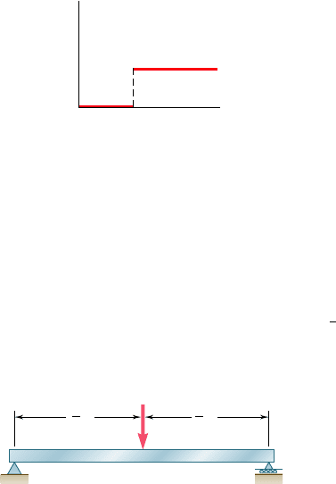
gularity function corresponding to n 5 0 is discontinuous at x 5 a
(Fig. 5.25). This function is called the step function. We wrote
Hx 2 aI
0
5
e
1 when x $ a
0 when x , a
(5.15)
Singularity functionsSingularity functions
Step functionStep function
0
(a) n ⫽ 0
⬍ x ⫺ a ⬎
0
ax
Fig. 5.25
The use of singularity functions makes it possible to represent the
shear or the bending moment in a beam by a single expression, valid
at any point of the beam. For example, the contribution to the shear
of the concentrated load P applied at the midpoint C of a simply
supported beam (Fig. 5.26) can be represented by 2P
H
x 2
1
2
L
I
0
, since
Using singularity functions to
express shear and bending moment
Using singularity functions to
express shear and bending moment
B
C
A
P
L
1
2
L
1
2
Fig. 5.26
bee80288_ch05_314-379.indd Page 372 11/12/10 7:24:36 PM user-f499bee80288_ch05_314-379.indd Page 372 11/12/10 7:24:36 PM user-f499 /Users/user-f499/Desktop/Temp Work/Don't Delete Job/MHDQ251:Beer:201/ch05/Users/user-f499/Desktop/Temp Work/Don't Delete Job/MHDQ251:Beer:201/ch05
Apago PDF Enhancer
373
this expression is equal to zero to the left of C, and to 2P to the
right of C. Adding the contribution of the reaction R
A
5
1
2
P at A, we
express the shear at any point of the beam as
V
1
x
2
5
1
2
P 2 P
H
x 2
1
2
L
I
0
The bending moment is obtained by integrating this expression:
M1x25
1
2
Px 2 P
H
x 2
1
2
L
I
1
The singularity functions representing, respectively, the load, shear,
and bending moment corresponding to various basic loadings were
given in Fig. 5.18 on page 353. We noted that a distributed loading
that does not extend to the right end of the beam, or which is dis-
continuous, should be replaced by an equivalent combination of
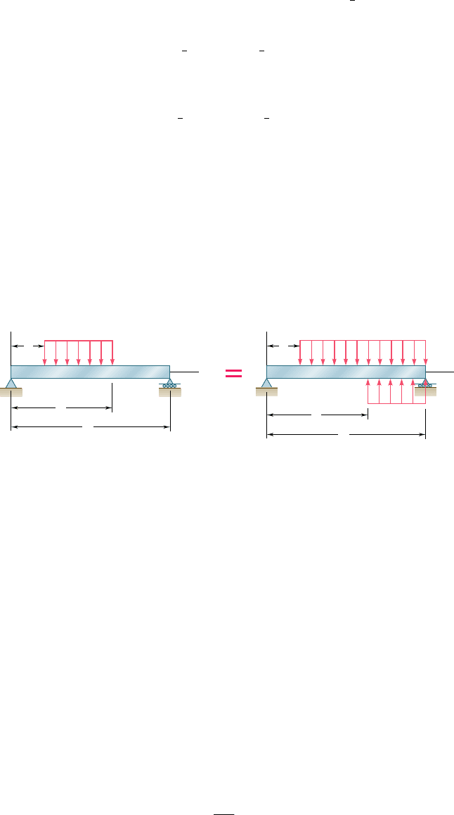
open-ended loadings. For instance, a uniformly distributed load
extending from x 5 a to x 5 b (Fig. 5.27) should be expressed as
w1x25 w
0
H
x 2 a
I
0
2 w
0
H
x 2 b
I
0
Equivalent open-ended loadingsEquivalent open-ended loadings
Fig. 5.27
x
O
w
w
0
b
L
a
x
O
w
w
0
⫺ w
0
b
L
a
Review and Summary
The contribution of this load to the shear and to the bending moment
can be obtained through two successive integrations. Care should be
taken, however, to also include in the expression for V(x) the contribu-
tion of concentrated loads and reactions, and to include in the expres-
sion for M(x) the contribution of concentrated couples [Examples 5.05
and 5.06, Sample Probs. 5.9 and 5.10]. We also observed that singular-
ity functions are particularly well suited to the use of computers.
We were concerned so far only with prismatic beams, i.e., beams of
uniform cross section. Considering in Sec. 5.6 the design of nonpris-
matic beams, i.e., beams of variable cross section, we saw that by
selecting the shape and size of the cross section so that its elastic
section modulus S 5 Iyc varied along the beam in the same way as
the bending moment M, we were able to design beams for which
s
m
at each section was equal to s
all
. Such beams, called beams of
constant strength, clearly provide a more effective use of the material
than prismatic beams. Their section modulus at any section along
the beam was defined by the relation
S 5
M
s
a
ll
(5.18)
Nonprismatic beamsNonprismatic beams
Beams of constant strengthBeams of constant strength
bee80288_ch05_314-379.indd Page 373 11/12/10 7:24:41 PM user-f499bee80288_ch05_314-379.indd Page 373 11/12/10 7:24:41 PM user-f499 /Users/user-f499/Desktop/Temp Work/Don't Delete Job/MHDQ251:Beer:201/ch05/Users/user-f499/Desktop/Temp Work/Don't Delete Job/MHDQ251:Beer:201/ch05
Apago PDF Enhancer
374
REVIEW PROBLEMS
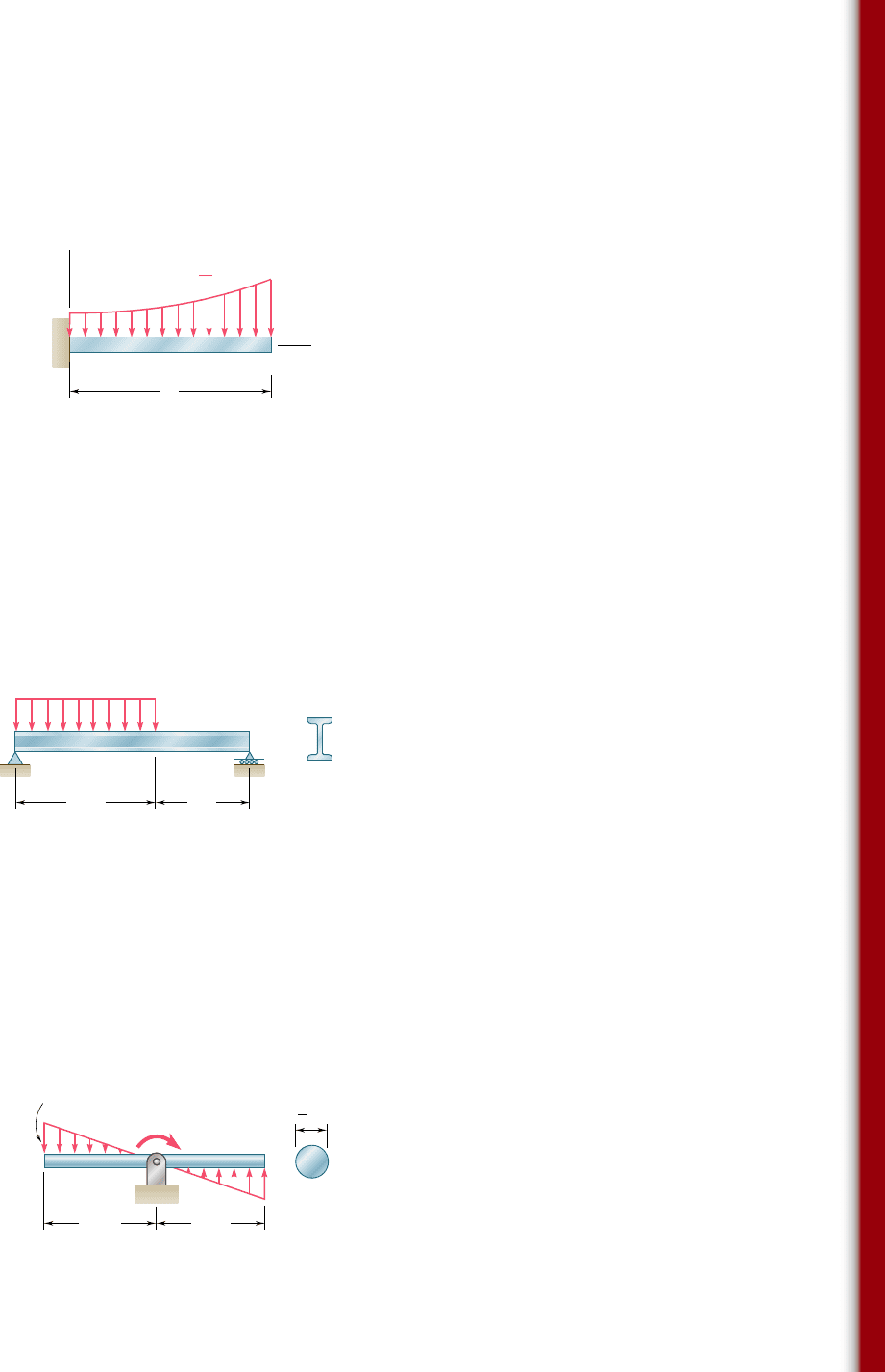
5.152 Draw the shear and bending-moment diagrams for the beam and
loading shown, and determine the maximum absolute value (a) of
the shear, (b) of the bending moment.
400 lb 1600 lb 400 lb
12 in. 12 in. 12 in. 12 in.
8 in.
8 in.
C
A
DEF
G
B
Fig. P5.152
5.154 Determine (a) the distance a for which the maximum absolute
value of the bending moment in the beam is as small as possible,
(b) the corresponding maximum normal stress due to bending.
(See hint of Prob. 5.27.)
H
A
7 @ 200 mm ⫽ 1400 mm
Hinge
30 mm
20 mm
CBDEFG
300 N 300 N 300 N40 N
Fig. P5.153
B
A
CD
a
5 ft8 ft
W14 ⫻ 22
10 kips5 kips
Fig. P5.154
5.153 Draw the shear and bending-moment diagrams for the beam and
loading shown and determine the maximum normal stress due to
bending.
bee80288_ch05_314-379.indd Page 374 10/27/10 9:59:38 PM user-f499bee80288_ch05_314-379.indd Page 374 10/27/10 9:59:38 PM user-f499 /Volumes/201/MHDQ251/bee80288_disk1of1/0073380288/bee80288_pagefiles/Volumes/201/MHDQ251/bee80288_disk1of1/0073380288/bee80288_pagefiles
Apago PDF Enhancer
375
Review Problems
5.155 Determine (a) the equations of the shear and bending-moment
curves for the beam and loading shown, (b) the maximum absolute
value of the bending moment in the beam.
w
A
L
B
x
w ⫽ w
0
l ⫹
(
(
x
2
L
2
Fig. P5.155
5.156 Draw the shear and bending-moment diagrams for the beam and
loading shown and determine the maximum normal stress due to
bending.
A
B
C
16 kN/m
1 m1.5 m
S150 ⫻ 18.6
Fig. P5.156
5.157 Knowing that beam AB is in equilibrium under the loading shown,
draw the shear and bending-moment diagrams and determine the
maximum normal stress due to bending.
Fig. P5.157
B
A
1.2 ft 1.2 ft
C
w
0
⫽ 50 lb/ft
T
w
0
3
4
in.
bee80288_ch05_314-379.indd Page 375 10/27/10 10:00:31 PM user-f499bee80288_ch05_314-379.indd Page 375 10/27/10 10:00:31 PM user-f499 /Volumes/201/MHDQ251/bee80288_disk1of1/0073380288/bee80288_pagefiles/Volumes/201/MHDQ251/bee80288_disk1of1/0073380288/bee80288_pagefiles
Apago PDF Enhancer
376
Analysis and Design of Beams for Bending
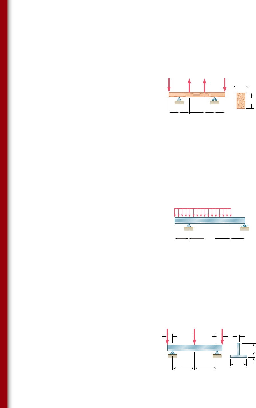
5.159 Knowing that the allowable stress for the steel used is 160 MPa,
select the most economical wide-flange beam to support the loading
shown.
5.160 Determine the largest permissible value of P for the beam and
loading shown, knowing that the allowable normal stress is 18 ksi
in tension and 218 ksi in compression.
P
10 in.
10 in.
60 in. 60 in.
1 in.
5 in.
1 in.
7 in.
E
DCB
A
PP
Fig. P5.160
C
D
A
B
0.8 m 0.8 m
2.4 m
50 kN/m
Fig. P5.159
5.158 For the beam and loading shown, design the cross section of the
beam, knowing that the grade of timber used has an allowable
normal stress of 1750 psi.
4.8 kips
4.8 kips
2 kips 2 kips
F
b
A
2 ft 2 ft 3 ft 2 ft 2 ft
9.5 in.
BC DE
Fig. P5.158
bee80288_ch05_314-379.indd Page 376 10/27/10 10:00:44 PM user-f499bee80288_ch05_314-379.indd Page 376 10/27/10 10:00:44 PM user-f499 /Volumes/201/MHDQ251/bee80288_disk1of1/0073380288/bee80288_pagefiles/Volumes/201/MHDQ251/bee80288_disk1of1/0073380288/bee80288_pagefiles
