Beer F.P., Johnston E.R., DeWolf J.T., Mazurek D.F. Mechanics of Materials
Подождите немного. Документ загружается.

Apago PDF Enhancer
397
Problems
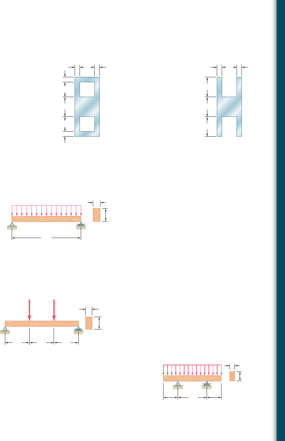
6.13 and 6.14 For a beam having the cross section shown, deter-
mine the largest allowable vertical shear if the shearing stress is
not to exceed 60 MPa.
6.15 For the beam and loading shown, determine the minimum required
depth h, knowing that for the grade of timber used, s
all
5 1750 psi
and t
all
5 130 psi.
10
10 10
30
10
Dimensions in mm
30
30
40
Fig. P6.13
Dimensions in mm
40
40
40
10 10
30
Fig. P6.14
16 ft
5 in.
A
B
h
750 lb/ft
Fig. P6.15
2.4 kN 4.8 kN
1 m 1 m 1 m
150 mm
AD
b
BC
Fig. P6.16
6.16 For the beam and loading shown, determine the minimum required
width b, knowing that for the grade of timber used, s
all
5 12 MPa
and t
all
5 825 kPa.
6.17 A timber beam AB of length L and rectangular cross section carries
a uniformly distributed load w and is supported as shown. (a) Show
that the ratio t
m
ys
m
of the maximum values of the shearing and
normal stresses in the beam is equal to 2hyL, where h and L are,
respectively, the depth and the length of the beam. (b) Determine
the depth h and the width b of the beam, knowing that L 5 5 m,
w 5 8 kN/m, t
m
5 1.08 MPa, and s
m
5 12 MPa.
B
b
h
A
CD
w
L/2
L/4L/4
Fig. P6.17
bee80288_ch06_380-435.indd Page 397 10/28/10 8:00:21 PM user-f499bee80288_ch06_380-435.indd Page 397 10/28/10 8:00:21 PM user-f499 /Volumes/201/MHDQ251/bee80288_disk1of1/0073380288/bee80288_pagefiles/Volumes/201/MHDQ251/bee80288_disk1of1/0073380288/bee80288_pagefiles
Apago PDF Enhancer
398
Shearing Stresses in Beams
and Thin-Walled Members
6.18 A timber beam AB of length L and rectangular cross section carries
a single concentrated load P at its midpoint C. (a) Show that the ratio
t
m
ys
m
of the maximum values of the shearing and normal stresses in
the beam is equal to hy2L, where h and L are, respectively, the depth
and the length of the beam. (b) Determine the depth h and the width
b of the beam, knowing that L 5 2 m, P 5 40 kN, t
m
5 960 kPa,
and s
m
5 12 MPa.
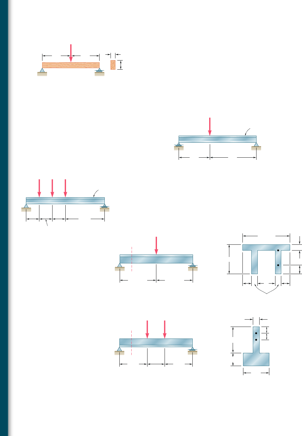
6.19 For the wide-flange beam with the loading shown, determine the
largest P that can be applied, knowing that the maximum normal
stress is 24 ksi and the largest shearing stress using the approxima-
tion t
m
5 VyA
web
is 14.5 ksi.
Fig. P6.18
B
b
h
C
L/2 L/2
A
P
6 ft
AC
B
9 ft
W24 ⫻ 104
P
Fig. P6.19
Fig. P6.20
0.6 m 0.6 m
0.6 m
1.8 m
AE
BCD
W360 ⫻ 122
PPP
6.20 For the wide-flange beam with the loading shown, determine the
largest load P that can be applied, knowing that the maximum
normal stress is 160 MPa and the largest shearing stress using the
approximation t
m
5 VyA
web
is 100 MPa.
6.21 and 6.22 For the beam and loading shown, consider section
n-n and determine the shearing stress at (a) point a, (b) point b.
Fig. P6.21 and P6.23
180 kN
500 mm 500 mm
100 mm
160 mm
30 mm 30 mm
30 mm
20 mm
20 mm
A
B
b
a
n
n
Fig. P6.22 and P6.24
16 in.
12 kips 12 kips
A
n
n
B
a
b
10 in.
16 in.
4 in.
1 in.
1 in.
1 in.
4 in.
2 in.
6.23 and 6.24 For the beam and loading shown, determine the larg-
est shearing stress in section n-n.
bee80288_ch06_380-435.indd Page 398 10/29/10 7:45:25 PM user-f499bee80288_ch06_380-435.indd Page 398 10/29/10 7:45:25 PM user-f499 /Volumes/201/MHDQ251/bee80288_disk1of1/0073380288/bee80288_pagefiles/Volumes/201/MHDQ251/bee80288_disk1of1/0073380288/bee80288_pagefiles
Apago PDF Enhancer
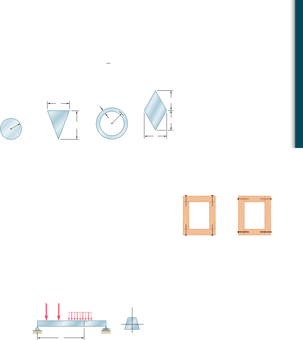
6.25 through 6.28 A beam having the cross section shown is sub-
jected to a vertical shear V. Determine (a) the horizontal line along
which the shearing stress is maximum, (b) the constant k in the
following expression for the maximum shearing stress
t
max
5 k
V
A
where A is the cross-sectional area of the beam.
c
Fig. P6.25
b
h
Fig. P6.26
r
m
t
m
Fig. P6.27
h
h
b
Fig. P6.28
6.6 LONGITUDINAL SHEAR ON A BEAM ELEMENT
OF ARBITRARY SHAPE
Consider a box beam obtained by nailing together four planks, as
shown in Fig. 6.22a. You learned in Sec. 6.2 how to determine the
shear per unit length, q, on the horizontal surfaces along which the
planks are joined. But could you determine q if the planks had been
joined along vertical surfaces, as shown in Fig. 6.22b? We examined
in Sec. 6.4 the distribution of the vertical components t
xy
of the
stresses on a transverse section of a W-beam or an S-beam and found
that these stresses had a fairly constant value in the web of the beam
and were negligible in its flanges. But what about the horizontal
components t
xz
of the stresses in the flanges?
To answer these questions we must extend the procedure
developed in Sec. 6.2 for the determination of the shear per unit
length, q, so that it will apply to the cases just described.
(a)(b)
Fig. 6.22 Box beam cross sections.
B
P
1
P
2
w
A
x
C
y
z
Fig. 6.4 (repeated) Beam example.
Consider the prismatic beam AB of Fig. 6.4, which has a verti-
cal plane of symmetry and supports the loads shown. At a distance
x from end A we detach again an element CDD9C9 of length Dx.
This element, however, will now extend from two sides of the beam
399
6.6 Longitudinal Shear on a Beam Element
of Arbitrary Shape
bee80288_ch06_380-435.indd Page 399 10/28/10 8:00:39 PM user-f499bee80288_ch06_380-435.indd Page 399 10/28/10 8:00:39 PM user-f499 /Volumes/201/MHDQ251/bee80288_disk1of1/0073380288/bee80288_pagefiles/Volumes/201/MHDQ251/bee80288_disk1of1/0073380288/bee80288_pagefiles
Apago PDF Enhancer
400
Shearing Stresses in Beams
and Thin-Walled Members
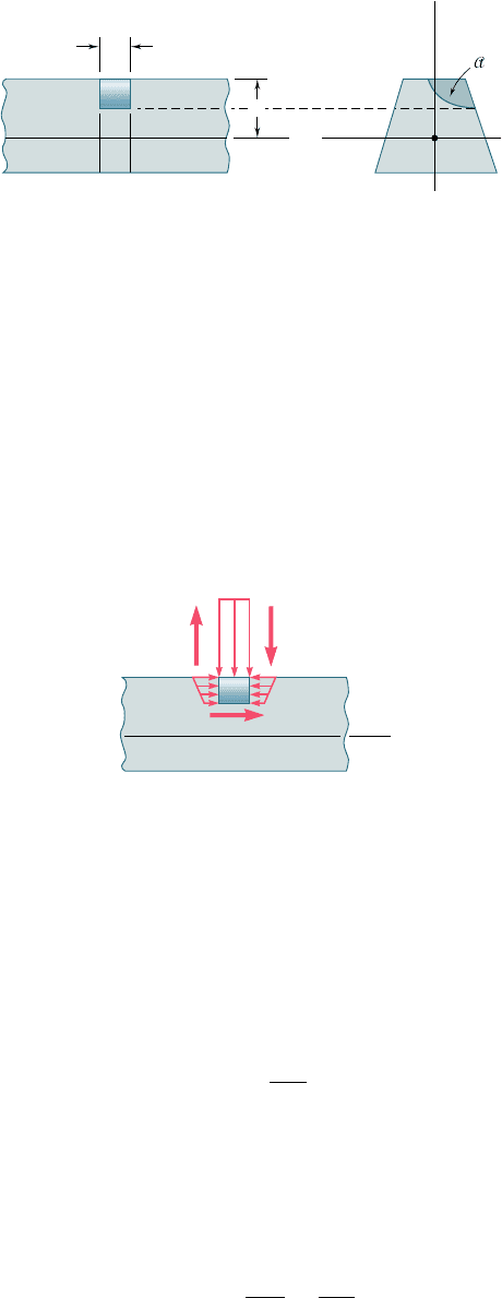
to an arbitrary curved surface (Fig. 6.23). The forces exerted on the
element include vertical shearing forces V9
C
and V9
D
, elementary hori-
zontal normal forces s
C
dA and s
D
dA, possibly a load w Dx, and a
longitudinal shearing force DH representing the resultant of the
elementary longitudinal shearing forces exerted on the curved sur-
face (Fig. 6.24). We write the equilibrium equation
1
ygF
x
5 0:
¢H 1
#
A
1s
C
2 s
D
2 dA 5 0
x
C
c
x
D
C'
D'
y
N.A.
z
Fig. 6.23 Short segment of beam example.
V
⬘
C
V
⬘
D
H
x
CD
dA
D
dA
C
w
Fig. 6.24 Forces exerted on
element.
where the integral is to be computed over the shaded area A of the
section. We observe that the equation obtained is the same as the
one we obtained in Sec. 6.2, but that the shaded area A over which
the integral is to be computed now extends to the curved surface.
The remainder of the derivation is the same as in Sec. 6.2. We
find that the longitudinal shear exerted on the beam element is
¢H 5
V
Q
I
¢x (6.4)
where I is the centroidal moment of inertia of the entire section, Q
the first moment of the shaded area A with respect to the neutral
axis, and V the vertical shear in the section. Dividing both members
of Eq. (6.4) by Dx, we obtain the horizontal shear per unit length,
or shear flow:
q 5
¢H
¢
x
5
V
Q
I
(6.5)
bee80288_ch06_380-435.indd Page 400 10/28/10 8:00:50 PM user-f499bee80288_ch06_380-435.indd Page 400 10/28/10 8:00:50 PM user-f499 /Volumes/201/MHDQ251/bee80288_disk1of1/0073380288/bee80288_pagefiles/Volumes/201/MHDQ251/bee80288_disk1of1/0073380288/bee80288_pagefiles
Apago PDF Enhancer
6.7 SHEARING STRESSES IN THIN-WALLED MEMBERS
We saw in the preceding section that Eq. (6.4) may be used to deter-
mine the longitudinal shear DH exerted on the walls of a beam ele-
ment of arbitrary shape and Eq. (6.5) to determine the corresponding
shear flow q. These equations will be used in this section to calculate
both the shear flow and the average shearing stress in thin-walled
401
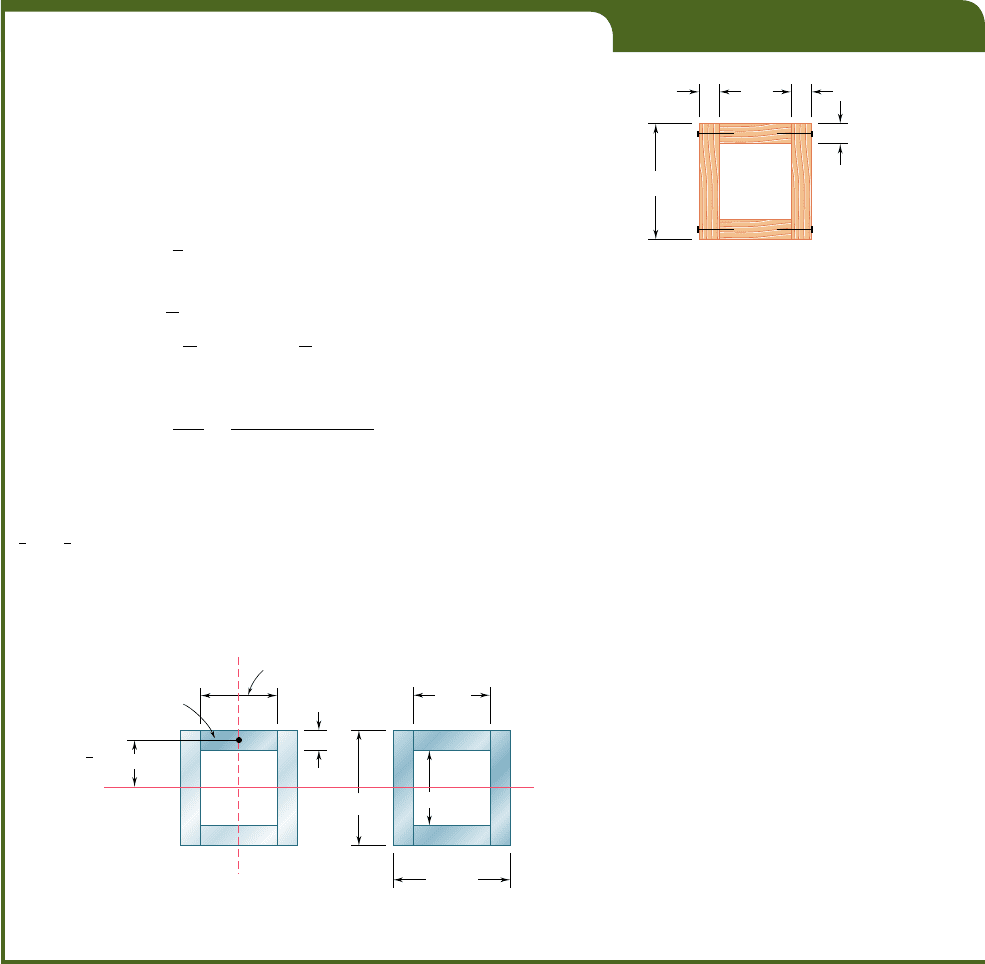
EXAMPLE 6.04
A square box beam is made of two 0.75 3 3-in. planks and two 0.75 3
4.5-in. planks, nailed together as shown (Fig. 6.25). Knowing that the spacing
between nails is 1.75 in. and that the beam is subjected to a vertical shear
of magnitude V 5 600 lb, determine the shearing force in each nail.
We isolate the upper plank and consider the total force per unit
length, q, exerted on its two edges. We use Eq. (6.5), where Q represents
the first moment with respect to the neutral axis of the shaded area A9 shown
in Fig. 6.26a, and where I is the moment of inertia about the same axis of
the entire cross-sectional area of the box beam (Fig. 6.26b). We have
Q 5 A¿
y 5 10.75 in.213 in.211.875 in.25 4.22 in
3
Recalling that the moment of inertia of a square of side a about a cen-
troidal axis is I 5
1
1
2
a
4
, we write
I 5
1
12
14.5 in.2
4
2
1
12
13 in.2
4
5 27.42 in
4
Substituting into Eq. (6.5), we obtain
q 5
V
Q
I
5
1600 lb214.22 in
3
2
27
.
42 in
4
5 92.3 lb/in.
Because both the beam and the upper plank are symmetric with respect
to the vertical plane of loading, equal forces are exerted on both edges
of the plank. The force per unit length on each of these edges is thus
1
2
q 5
1
2
192.325 46.15 lb/in. Since the spacing between nails is 1.75 in.,
the shearing force in each nail is
F 5 11.75 in.2146.15 lb/in.25 80.8 lb
0.75 in. 0.75 in.
0.75 in.
4.5 in.
3 in.
Fig. 6.25
0.75 in.
y
1.875 in.
N.A.
4.5 in.
4.5 in.
3 in.
3 in.
3 in.
(a)(b)
A'
Fig. 6.26
bee80288_ch06_380-435.indd Page 401 10/28/10 8:00:55 PM user-f499bee80288_ch06_380-435.indd Page 401 10/28/10 8:00:55 PM user-f499 /Volumes/201/MHDQ251/bee80288_disk1of1/0073380288/bee80288_pagefiles/Volumes/201/MHDQ251/bee80288_disk1of1/0073380288/bee80288_pagefiles
Apago PDF Enhancer
402
Shearing Stresses in Beams
and Thin-Walled Members
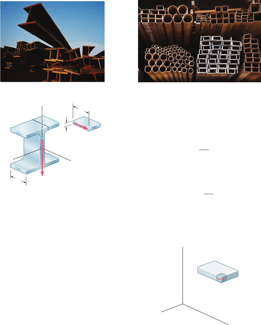
members such as the flanges of wide-flange beams (Photo 6.2) and
box beams, or the walls of structural tubes (Photo 6.3).
Photo 6.2 Wide-flange beams. Photo 6.3 Box beams and tubes.
Consider, for instance, a segment of length Dx of a wide-flange
beam (Fig. 6.27a) and let V be the vertical shear in the transverse
section shown. Let us detach an element ABB9A9 of the upper flange
(Fig. 6.27b). The longitudinal shear DH exerted on that element can
be obtained from Eq. (6.4):
¢H 5
V
Q
I
¢x (6.4)
Dividing DH by the area DA 5 t Dx of the cut, we obtain for the
average shearing stress exerted on the element the same expression
that we had obtained in Sec. 6.3 in the case of a horizontal cut:
t
ave
5
V
Q
It
(6.6)
Note that t
ave
now represents the average value of the shearing stress
t
zx
over a vertical cut, but since the thickness t of the flange is small,
there is very little variation of t
zx
across the cut. Recalling that t
xz
5
t
zx
(Fig. 6.28), we conclude that the horizontal component t
xz
of the
y
B'
B'
B
B
H
V
x
x
A
A
A'
A'
t
x
z
(a)
(b)
Fig. 6.27 Wide-flange beam segment.
y
zx
xz
x
z
Fig. 6.28 Segment of beam flange.
bee80288_ch06_380-435.indd Page 402 11/13/10 12:25:40 AM user-f499bee80288_ch06_380-435.indd Page 402 11/13/10 12:25:40 AM user-f499 /Users/user-f499/Desktop/Temp Work/Don't Delete Job/MHDQ251:Beer:201/ch06/Users/user-f499/Desktop/Temp Work/Don't Delete Job/MHDQ251:Beer:201/ch06
Apago PDF Enhancer
403
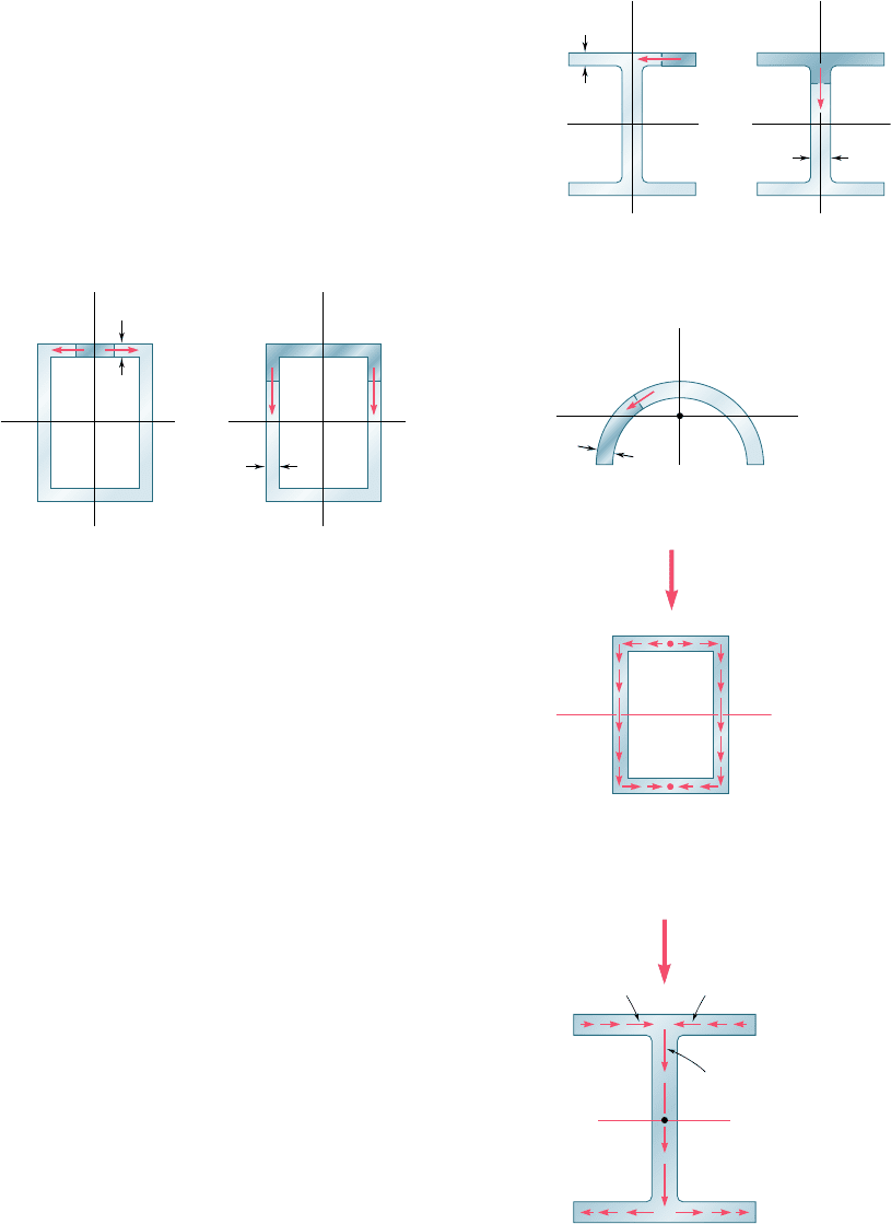
shearing stress at any point of a transverse section of the flange can
be obtained from Eq. (6.6), where Q is the first moment of the
shaded area about the neutral axis (Fig. 6.29a). We recall that a
similar result was obtained in Sec. 6.4 for the vertical component t
xy
of the shearing stress in the web (Fig. 6.29b). Equation (6.6) can be
used to determine shearing stresses in box beams (Fig. 6.30), half
pipes (Fig. 6.31), and other thin-walled members, as long as the loads
are applied in a plane of symmetry of the member. In each case, the
cut must be perpendicular to the surface of the member, and Eq. (6.6)
will yield the component of the shearing stress in the direction of the
tangent to that surface. (The other component may be assumed equal
to zero, in view of the proximity of the two free surfaces.)
†We recall that the concept of shear flow was used to analyze the distribution of shearing
stresses in thin-walled hollow shafts (Sec. 3.13). However, while the shear flow in a hollow
shaft is constant, the shear flow in a member under a transverse loading is not.
N.A.
xz
y
t
z
(a)
N.A.
xy
y
t
z
(b)
Fig. 6.29 Wide-flange beam.
N.A.
N.A.
xy
xz
xz
xy
t
t
zz
y
y
(a)(b)
Fig. 6.30 Box beam.
N.A.
z
y
t
C
Fig. 6.31 Half pipe beam.
B
N.A.
A
qq
CC'
B'
DE
D'
V
Fig. 6.32 Shear flow q
in box beam section.
N.A.
q
1
q
q ⫽ q
1
⫹ q
2
q
2
q
1
q
2
A
D
B
C
A'
E'E
V
Fig. 6.33 Shear flow q in
wide-flange beam section.
Comparing Eqs. (6.5) and (6.6), we note that the product of the
shearing stress t at a given point of the section and of the thickness
t of the section at that point is equal to q. Since V and I are constant
in any given section, q depends only upon the first moment Q and,
thus, can easily be sketched on the section. In the case of a box beam,
for example (Fig. 6.32), we note that q grows smoothly from zero at
A to a maximum value at C and C9 on the neutral axis, and then
decreases back to zero as E is reached. We also note that there is no
sudden variation in the magnitude of q as we pass a corner at B, D,
B9, or D9, and that the sense of q in the horizontal portions of the
section may be easily obtained from its sense in the vertical portions
(which is the same as the sense of the shear V). In the case of a wide-
flange section (Fig. 6.33), the values of q in portions AB and A9B of
the upper flange are distributed symmetrically. As we turn at B into
the web, the values of q corresponding to the two halves of the flange
must be combined to obtain the value of q at the top of the web.
After reaching a maximum value at C on the neutral axis, q decreases,
and at D splits into two equal parts corresponding to the two halves
of the lower flange. The name of shear flow commonly used to refer
to the shear per unit length, q, reflects the similarity between the
properties of q that we have just described and some of the charac-
teristics of a fluid flow through an open channel or pipe.†
6.7 Shearing Stresses in Thin-Walled Members
bee80288_ch06_380-435.indd Page 403 10/29/10 7:45:38 PM user-f499bee80288_ch06_380-435.indd Page 403 10/29/10 7:45:38 PM user-f499 /Volumes/201/MHDQ251/bee80288_disk1of1/0073380288/bee80288_pagefiles/Volumes/201/MHDQ251/bee80288_disk1of1/0073380288/bee80288_pagefiles
Apago PDF Enhancer
404
Shearing Stresses in Beams
and Thin-Walled Members
So far we have assumed that all the loads were applied in a
plane of symmetry of the member. In the case of members pos-
sessing two planes of symmetry, such as the wide-flange beam of
Fig. 6.29 or the box beam of Fig. 6.30, any load applied through
the centroid of a given cross section can be resolved into compo-
nents along the two axes of symmetry of the section. Each compo-
nent will cause the member to bend in a plane of symmetry, and
the corresponding shearing stresses can be obtained from Eq. (6.6).
The principle of superposition can then be used to determine the
resulting stresses.
However, if the member considered possesses no plane of sym-
metry, or if it possesses a single plane of symmetry and is subjected
to a load that is not contained in that plane, the member is observed
to bend and twist at the same time, except when the load is applied
at a specific point, called the shear center. Note that the shear center
generally does not coincide with the centroid of the cross section.
The determination of the shear center of various thin-walled shapes
is discussed in Sec. 6.9.
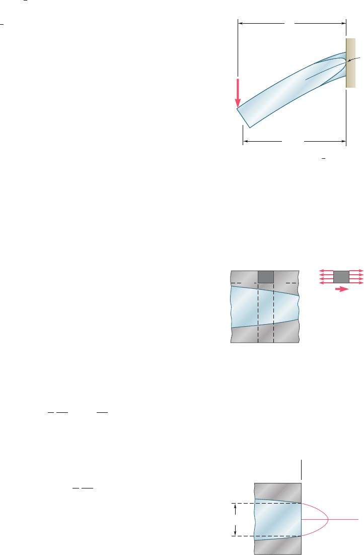
*6.8 PLASTIC DEFORMATIONS
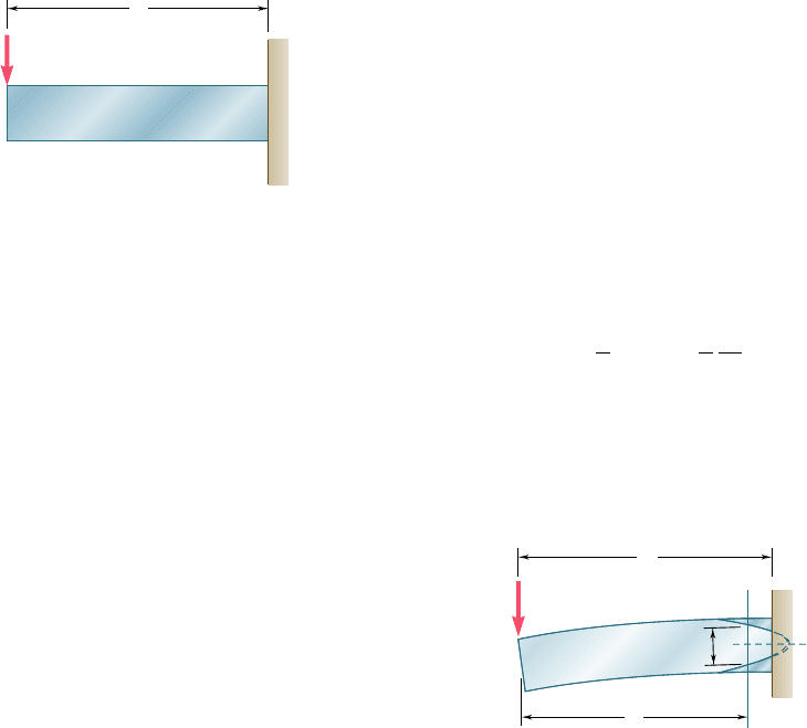
Consider a cantilever beam AB of length L and rectangular cross sec-
tion, subjected at its free end A to a concentrated load P (Fig. 6.34).
The largest value of the bending moment occurs at the fixed end B
and is equal to M 5 PL. As long as this value does not exceed the
maximum elastic moment M
Y
, that is, as long as PL # M
Y
, the normal
stress s
x
will not exceed the yield strength s
Y
anywhere in the beam.
However, as P is increased beyond the value M
Y
yL, yield is initiated
at points B and B9 and spreads toward the free end of the beam.
Assuming the material to be elastoplastic, and considering a cross
section CC9 located at a distance x from the free end A of the beam
(Fig. 6.35), we obtain the half-thickness y
Y
of the elastic core in that
section by making M 5 Px in Eq. (4.38) of Sec. 4.9. We have
Px 5
3
2
M
Y
a
1 2
1
3
y
2
Y
c
2
b
(6.14)
where c is the half-depth of the beam. Plotting y
Y
against x, we
obtain the boundary between the elastic and plastic zones.
P
A
L
B
B'
Fig. 6.34 (PL # M
Y
)
A
L
x
C
2y
Y
C'
B
'
B
P
Fig. 6.35 (PL . M
Y
)
bee80288_ch06_380-435.indd Page 404 10/28/10 8:01:08 PM user-f499bee80288_ch06_380-435.indd Page 404 10/28/10 8:01:08 PM user-f499 /Volumes/201/MHDQ251/bee80288_disk1of1/0073380288/bee80288_pagefiles/Volumes/201/MHDQ251/bee80288_disk1of1/0073380288/bee80288_pagefiles
Apago PDF Enhancer
405
As long as PL ,
3
2
M
Y
, the parabola defined by Eq. (6.14)
intersects the line BB9, as shown in Fig. 6.38. However, when PL
reaches the value
3
2
M
Y
, that is, when PL 5 M
p
, where M
p
is the
plastic moment defined in Sec. 4.9, Eq. (6.14) yields y
Y
5 0 for
x 5 L, which shows that the vertex of the parabola is now located
in section BB9, and that this section has become fully plastic
(Fig. 6.36). Recalling Eq. (4.40) of Sec. 4.9, we also note that the
radius of curvature r of the neutral surface at that point is equal
to zero, indicating the presence of a sharp bend in the beam at its
fixed end. We say that a plastic hinge has developed at that point.
The load P 5 M
p
yL is the largest load that can be supported by
the beam.
The above discussion was based only on the analysis of the
normal stresses in the beam. Let us now examine the distribution
of the shearing stresses in a section that has become partly plastic.
Consider the portion of beam CC0D0D located between the trans-
verse sections CC9 and DD9, and above the horizontal plane D0C0
(Fig. 6.37a). If this portion is located entirely in the plastic zone,
the normal stresses exerted on the faces CC0 and DD0 will be uni-
formly distributed and equal to the yield strength s
Y
(Fig. 6.40b).
The equilibrium of the free body CC0D0D thus requires that the
horizontal shearing force DH exerted on its lower face be equal to
zero. It follows that the average value of the horizontal shearing
stress t
yx
across the beam at C0 is zero, as well as the average value
of the vertical shearing stress t
xy
. We thus conclude that the vertical
shear V 5 P in section CC9 must be distributed entirely over the
portion EE9 of that section that is located within the elastic zone
(Fig. 6.38). It can be shown† that the distribution of the shearing
stresses over EE9 is the same as in an elastic rectangular beam of
the same width b as beam AB, and of depth equal to the thickness
2y
Y
of the elastic zone. Denoting by A9 the area 2by
Y
of the elastic
portion of the cross section, we have
t
xy
5
3
2
P
A¿
a1 2
y
2
y
2
Y
b
(6.15)
The maximum value of the shearing stress occurs for y 5 0 and is
t
max
5
3
2
P
A¿
(6.16)
As the area A9 of the elastic portion of the section decreases,
t
max
increases and eventually reaches the yield strength in shear t
Y
.
Thus, shear contributes to the ultimate failure of the beam. A more
exact analysis of this mode of failure should take into account the
combined effect of the normal and shearing stresses.
Fig. 6.36 (PL 5 M
P
5
3
2
M
Y
)
A
L
x L
B
y
Y
0
B'
P
6.8 Plastic Deformations
†See Prob. 6.60.
D
D''
D''
C''
C''
CD
H
Y
Y
C
D' C'
(b)
(a)
Fig. 6.37 Beam segment.
C'
E'
E
C
y
xy
max
2y
Y
PLASTIC
PLASTIC
ELASTIC
Fig. 6.38
bee80288_ch06_380-435.indd Page 405 10/28/10 8:01:13 PM user-f499bee80288_ch06_380-435.indd Page 405 10/28/10 8:01:13 PM user-f499 /Volumes/201/MHDQ251/bee80288_disk1of1/0073380288/bee80288_pagefiles/Volumes/201/MHDQ251/bee80288_disk1of1/0073380288/bee80288_pagefiles
Apago PDF Enhancer
406
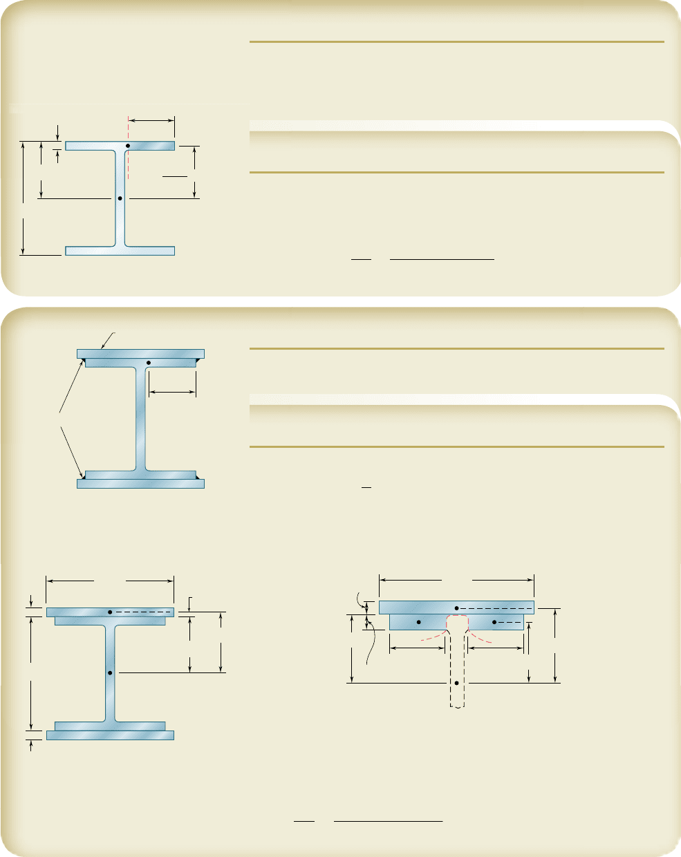
SAMPLE PROBLEM 6.3
Knowing that the vertical shear is 50 kips in a W10 3 68 rolled-steel beam,
determine the horizontal shearing stress in the top flange at a point a located
4.31 in. from the edge of the beam. The dimensions and other geometric
data of the rolled-steel section are given in Appendix C.
SOLUTION
We isolate the shaded portion of the flange by cutting along the dashed line
that passes through point a.
Q 5 14.31 in.210.770 in.214.815 in.25 15.98 in
3
t 5
VQ
It
5
150 kips2115.98 in
3
2
1
394 in
4
21
0.770 in.
2
t 5 2.63 ksib
4.815 in.5.2
5.2 in.
t
f
0.770 in.
I
x
394 in
4
a
C
0.770
4.31 in.
10.4 in.
2
SAMPLE PROBLEM 6.4
Solve Sample Prob. 6.3, assuming that 0.75 3 12-in. plates have been attached
to the flanges of the W10 3 68 beam by continuous fillet welds as shown.
SOLUTION
For the composite beam the centroidal moment of inertia is
I 5 394 in
4
1 23
1
12
112 in.210.75 in.2
3
1 112 in.210.75 in.215.575 in.2
2
4
I 5 954 in
4
Since the top plate and the flange are connected only at the welds, we find the
shearing stress at a by passing a section through the flange at a, between the
plate and the flange, and again through the flange at the symmetric point a9.
For the shaded area that we have isolated, we have
t 5 2t
f
5 210.770 in.25 1.540 in.
Q 5 2314.31 in.210.770 in.214.815 in.241 112 in.210.75 in.215.575 in.2
Q 5 82.1 in
3
t 5
VQ
It
5
150 kips2182.1 in
3
2
1954 in
4
211.540 in.2
t 5 2.79 ksib
C
12 in.
5.2 in.
5.575 in.
0.375 in.
10.4 in.
0.75 in.
0.75 in.
12 in.
5.2 in.
0.75 in.
0.770 in.
4.31 in. 4.31 in.
4.815 in.
5.575 in.
a' a
C
a
W
elds
0.75 in. 12 in.
4.31 in.
bee80288_ch06_380-435.indd Page 406 10/28/10 8:01:18 PM user-f499bee80288_ch06_380-435.indd Page 406 10/28/10 8:01:18 PM user-f499 /Volumes/201/MHDQ251/bee80288_disk1of1/0073380288/bee80288_pagefiles/Volumes/201/MHDQ251/bee80288_disk1of1/0073380288/bee80288_pagefiles
