Beer F.P., Johnston E.R., DeWolf J.T., Mazurek D.F. Mechanics of Materials
Подождите немного. Документ загружается.

Apago PDF Enhancer
417
Fig. 6.48
B
e
O
D
E
A
t
h
b
Fig. 6.49
B
N.A.
h/2
t
A
D
E
s
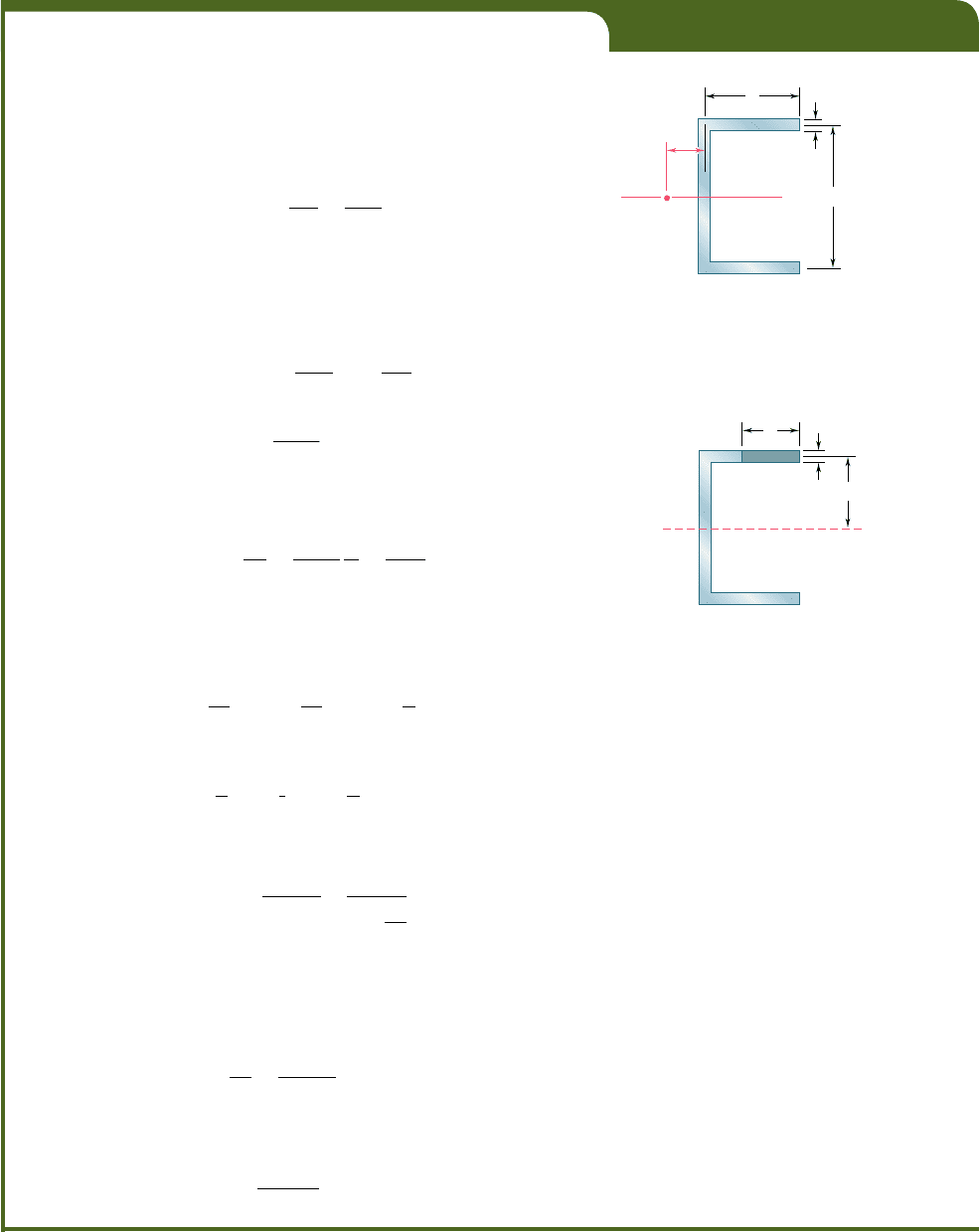
EXAMPLE 6.05
Determine the shear center O of a channel section of uniform thickness
(Fig. 6.48), knowing that b 5 4 in., h 5 6 in., and t 5 0.15 in.
Assuming that the member does not twist, we first determine the
shear flow q in flange AB at a distance s from A (Fig. 6.49). Recalling
Eq. (6.5) and observing that the first moment Q of the shaded area with
respect to the neutral axis is Q 5 (st)(hy2), we write
q 5
VQ
I
5
Vsth
2
I
(6.20)
where V is the vertical shear and I the moment of inertia of the section
with respect to the neutral axis.
Recalling Eq. (6.17), we determine the magnitude of the shearing
force F exerted on flange AB by integrating the shear flow q from A to B:
F 5
#
b
0
q ds 5
#
b
0
Vsth
2I
ds 5
Vth
2I
#
b
0
s ds
F 5
Vthb
2
4I
(6.21)
The distance e from the center line of the web BD to the shear center
O can now be obtained from Eq. (6.19):
e 5
F
h
V
5
Vthb
2
4I
h
V
5
th
2
b
2
4I
(6.22)
The moment of inertia I of the channel section can be expressed as
follows:
I 5 I
web
1
2
I
flange
5
1
12
th
3
1 2
c
1
12
bt
3
1 bt
a
h
2
b
2
d
Neglecting the term containing t
3
, which is very small, we have
I 5
1
12
th
3
1
1
2
tbh
2
5
1
12
th
2
1
6b 1 h
2
(6.23)
Substituting this expression into (6.22), we write
e 5
3b
2
6b 1 h
5
b
2 1
h
3
b
(6.24)
We note that the distance e does not depend upon t and can vary from
0 to by2, depending upon the value of the ratio hy3b. For the given chan-
nel section, we have
h
3b
5
6 in
.
3
1
4 in.
2
5 0.5
and
e 5
4
in.
2 1 0
.
5
5 1.6 in.
bee80288_ch06_380-435.indd Page 417 10/28/10 8:02:46 PM user-f499bee80288_ch06_380-435.indd Page 417 10/28/10 8:02:46 PM user-f499 /Volumes/201/MHDQ251/bee80288_disk1of1/0073380288/bee80288_pagefiles/Volumes/201/MHDQ251/bee80288_disk1of1/0073380288/bee80288_pagefiles
Apago PDF Enhancer
418
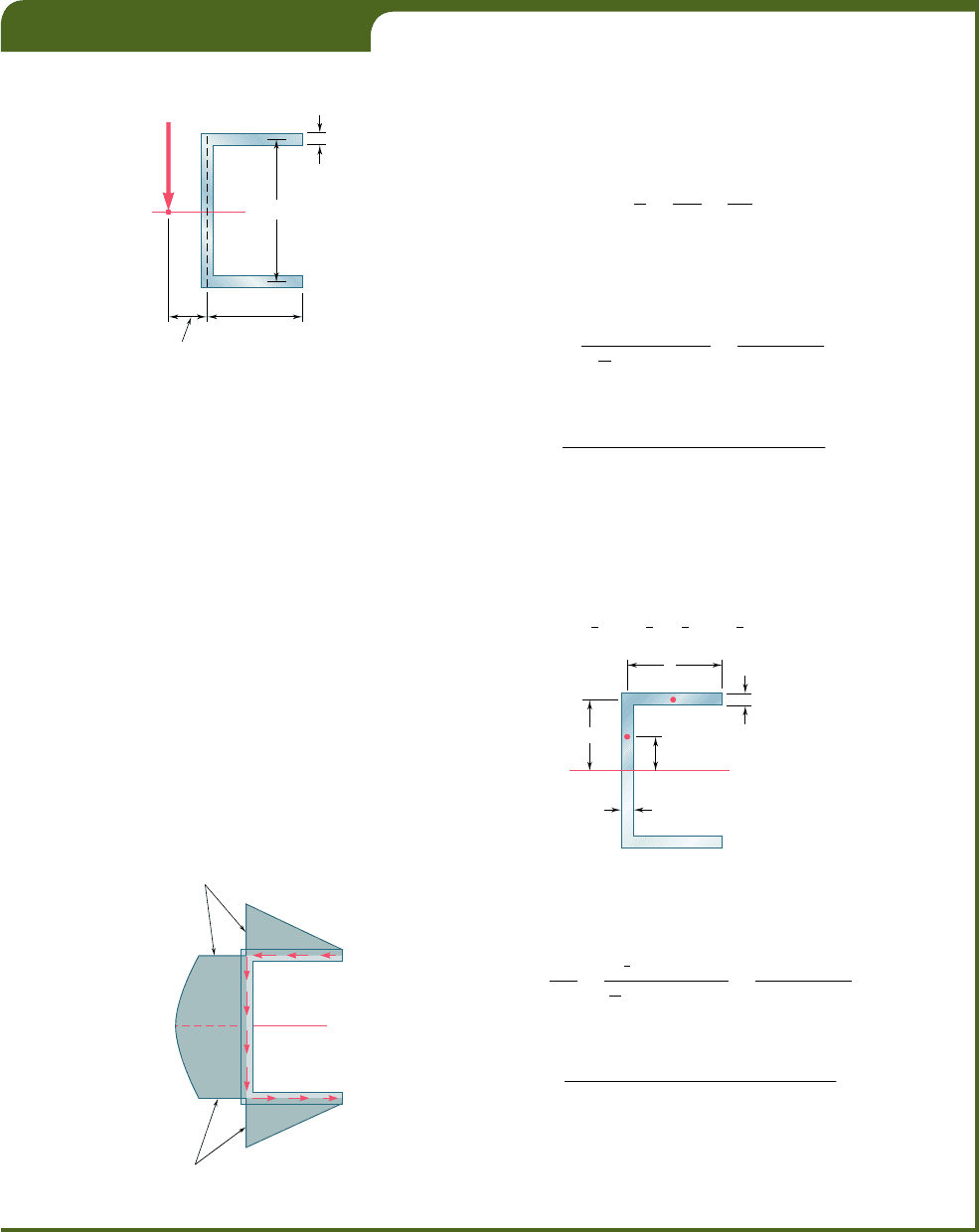
For the channel section of Example 6.05 determine the distribution of
the shearing stresses caused by a 2.5-kip vertical shear V applied at the
shear center O (Fig. 6.50).
Shearing stresses in flanges. Since V is applied at the shear
center, there is no torsion, and the stresses in flange AB are obtained from
Eq. (6.20) of Example 6.05. We have
t 5
q
t
5
VQ
I
t
5
Vh
2I
s
(6.25)
which shows that the stress distribution in flange AB is linear. Letting
s 5 b and substituting for I from Eq. (6.23), we obtain the value of the
shearing stress at B:
t
B
5
V
hb
2
1
1
12
th
2
21
6b 1 h
2
5
6V
b
th16b 1 h2
(6.26)
Letting V 5 2.5 kips, and using the given dimensions, we have
t
B
5
6
1
2.5 kips
21
4 in.
2
1
0.15 in.
21
6 in.
21
6 3 4 in. 1 6 in.
2
5 2
.
22
ks
i
Shearing stresses in web. The distribution of the shearing stresses
in the web BD is parabolic, as in the case of a W-beam, and the maximum
stress occurs at the neutral axis. Computing the first moment of the upper half
of the cross section with respect to the neutral axis (Fig. 6.51), we write
Q 5 bt1
1
2
h21
1
2
ht 1
1
4
h25
1
8
ht14b 1 h2 (6.27)
EXAMPLE 6.06
B
e 1.6 in.
b 4 in.
h 6 in.
t 0.15 in.
V
2.5 kips
O
D
E
A
Fig. 6.50
h/2
t
t
A
E
N.A.
D
B
h/4
b
Fig. 6.51
B
max
3.06 ksi
D
E
N.A.
A
B
2.22 ksi
D
2.22 ksi
Fig. 6.52
Substituting for I and Q from (6.23) and (6.27), respectively, into the
expression for the shearing stress, we have
t
max
5
V
Q
It
5
V1
1
8
ht214b 1 h2
1
12
th
2
1
6b 1 h
2
t
5
3V14b 1 h
2
2th16b 1 h2
or, with the given data,
t
max
5
3
1
2.5 kips
21
4 3 4 in. 1 6 in.
2
2
1
0.15 in.
21
6 in.
21
6 3 4 in. 1 6 in.
2
5 3
.
06
ks
i
Distribution of stresses over the section. The distribution of
the shearing stresses over the entire channel section has been plotted in
Fig. 6.52.
bee80288_ch06_380-435.indd Page 418 10/28/10 8:02:48 PM user-f499bee80288_ch06_380-435.indd Page 418 10/28/10 8:02:48 PM user-f499 /Volumes/201/MHDQ251/bee80288_disk1of1/0073380288/bee80288_pagefiles/Volumes/201/MHDQ251/bee80288_disk1of1/0073380288/bee80288_pagefiles
Apago PDF Enhancer
419
Fig. 6.53
B
6 in.
0.15 in.
1.143 in.
4 in.
V 2.5 kips
C
D
E
A
B
1.143 in.
e 1.6 in.
V
C
O
D
E
A
B
V
T
C
O
D
E
A
B
V 2.5 kips
Bending Twisting
O
D
E
A
a
b t
T 6.86 kip
?
in.
(a)(b)(c)(d)
Fig. 6.54
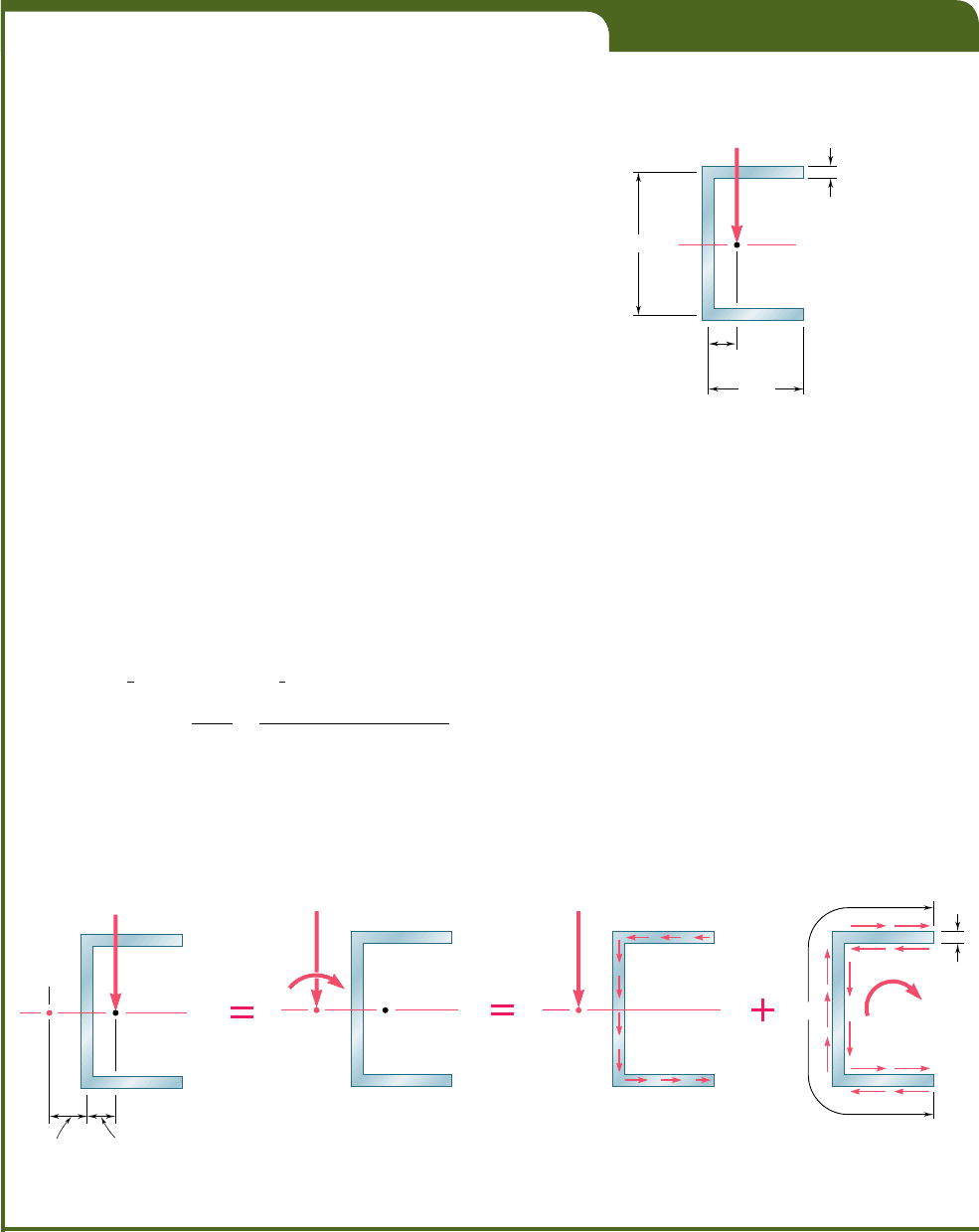
EXAMPLE 6.07
For the channel section of Example 6.05, and neglecting stress concentra-
tions, determine the maximum shearing stress caused by a 2.5-kip vertical
shear V applied at the centroid C of the section, which is located 1.143 in.
to the right of the center line of the web BD (Fig. 6.53).
Equivalent force-couple system at shear center. The shear
center O of the cross section was determined in Example 6.05 and found
to be at a distance e 5 1.6 in. to the left of the center line of the web
BD. We replace the shear V (Fig. 6.54a) by an equivalent force-couple
system at the shear center O (Fig. 6.54b). This system consists of a 2.5-kip
force V and of a torque T of magnitude
T 5 V
1
OC
2
5
1
2.5 kips
21
1.6 in. 1 1.143 in.
2
5 6.86
k
ip ? in.
Stresses due to bending. The 2.5-kip force V causes the mem-
ber to bend, and the corresponding distribution of shearing stresses in
the section (Fig. 6.54c) was determined in Example 6.06. We recall that
the maximum value of the stress due to this force was found to be
1
t
max
2
bending
5 3.06 ksi
Stresses due to twisting. The torque T causes the member to twist,
and the corresponding distribution of stresses is shown in Fig. 6.54d. We
recall from Sec. 3.12 that the membrane analogy shows that, in a thin-walled
member of uniform thickness, the stress caused by a torque T is maximum
along the edge of the section. Using Eqs. (3.45) and (3.43) with
a
5
4
in
.
1
6
in
.
1
4
in
.
5
14
in
.
b
5
t
5 0
.
15 in
.
b
y
a 5 0.0107
we have
c
1
5
1
3
1
1 2 0.630b
y
a
2
5
1
3
1
1 2 0.630 3 0.0107
2
5 0.331
1t
max
2
twisting
5
T
c
1
ab
2
5
6.86
k
ip ? in.
1
0.331
21
14 in.
21
0.15 in.
2
2
5 65.8 ksi
Combined stresses. The maximum stress due to the combined
bending and twisting occurs at the neutral axis, on the inside surface of
the web, and is
t
max
5 3.06
k
si 1 65.8
k
si 5 68.9
k
si
bee80288_ch06_380-435.indd Page 419 11/13/10 12:26:01 AM user-f499bee80288_ch06_380-435.indd Page 419 11/13/10 12:26:01 AM user-f499 /Users/user-f499/Desktop/Temp Work/Don't Delete Job/MHDQ251:Beer:201/ch06/Users/user-f499/Desktop/Temp Work/Don't Delete Job/MHDQ251:Beer:201/ch06
Apago PDF Enhancer
420
Shearing Stresses in Beams
and Thin-Walled Members
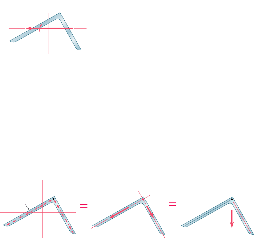
Turning our attention to thin-walled members possessing no
plane of symmetry, we now consider the case of an angle shape
subjected to a vertical load P. If the member is oriented in such a
way that the load P is perpendicular to one of the principal centroi-
dal axes Cz of the cross section, the couple vector M representing
the bending moment in a given section will be directed along Cz
(Fig. 6.55), and the neutral axis will coincide with that axis (cf. Sec.
4.13). Equation (4.16), therefore, is applicable and can be used to
compute the normal stresses in the section. We now propose to de-
termine where the load P should be applied if Eq. (6.6) is to define
the shearing stresses in the section, i.e., if the member is to bend
without twisting.
Let us assume that the shearing stresses in the section are defined
by Eq. (6.6). As in the case of the channel member considered earlier,
the elementary shearing forces exerted on the section can be expressed
as dF 5 q ds, with q 5 VQyI, where Q represents a first moment
with respect to the neutral axis (Fig. 6.56a). We note that the resultant
of the shearing forces exerted on portion OA of the cross section is a
force F
1
directed along OA, and that the resultant of the shearing
forces exerted on portion OB is a force F
2
along OB (Fig. 6.56b). Since
both F
1
and F
2
pass through point O at the corner of the angle, it
follows that their own resultant, which is the shear V in the section,
must also pass through O (Fig. 6.56c). We conclude that the mem-
ber will not be twisted if the line of action of the load P passes
through the corner O of the section in which it is applied.
y
z
M
N.A.
C
A
B
Fig. 6.55 Beam without plane
of symmetry.
y
z
dF q ds
N.A.
C
A
B
O
(a) Shear stresses (b) Resultant forces on elements (c) Placement of V to eliminate twisting
V
A
O
B
F
1
F
2
A
O
B
Fig. 6.56
The same reasoning can be applied when the load P is perpen-
dicular to the other principal centroidal axis Cy of the angle section.
And, since any load P applied at the corner O of a cross section can
be resolved into components perpendicular to the principal axes, it
follows that the member will not be twisted if each load is applied
at the corner O of a cross section. We thus conclude that O is the
shear center of the section.
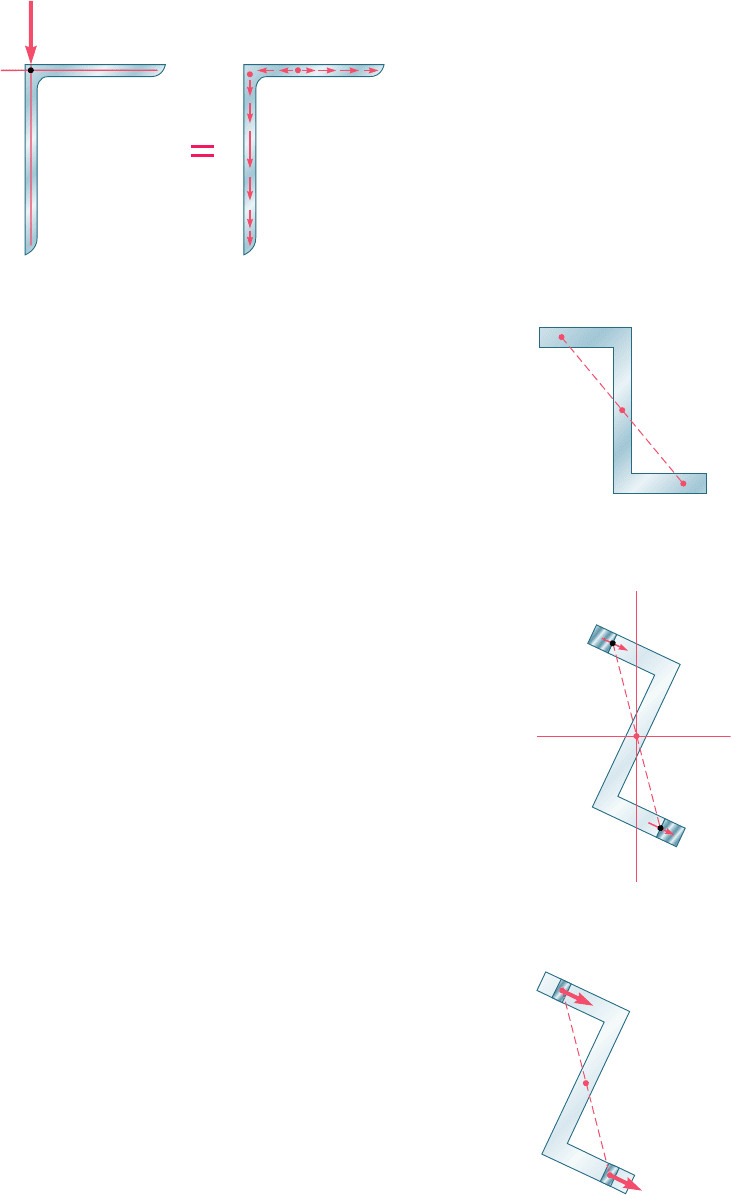
Angle shapes with one vertical and one horizontal leg are
encountered in many structures. It follows from the preceding dis-
cussion that such members will not be twisted if vertical loads are
applied along the center line of their vertical leg. We note from
Fig. 6.57 that the resultant of the elementary shearing forces exerted
on the vertical portion OA of a given section will be equal to the
bee80288_ch06_380-435.indd Page 420 10/28/10 8:03:03 PM user-f499bee80288_ch06_380-435.indd Page 420 10/28/10 8:03:03 PM user-f499 /Volumes/201/MHDQ251/bee80288_disk1of1/0073380288/bee80288_pagefiles/Volumes/201/MHDQ251/bee80288_disk1of1/0073380288/bee80288_pagefiles
Apago PDF Enhancer
421
shear V, while the resultant of the shearing forces on the horizontal
portion OB will be zero:
#
A
O
q ds 5 V
#
B
O
q ds 5 0
This does not mean, however, that there will be no shearing stress in
the horizontal leg of the member. By resolving the shear V into com-
ponents perpendicular to the principal centroidal axes of the section
and computing the shearing stress at every point, we would verify that
t is zero at only one point between O and B (see Sample Prob. 6.6).
Another type of thin-walled member frequently encountered in
practice is the Z shape. While the cross section of a Z shape does not
possess any axis of symmetry, it does possess a center of symmetry O
(Fig. 6.58). This means that, to any point H of the cross section cor-
responds another point H9 such that the segment of straight line HH9
is bisected by O. Clearly, the center of symmetry O coincides with
the centroid of the cross section. As you will see presently, point O
is also the shear center of the cross section.
As we did earlier in the case of an angle shape, we assume that
the loads are applied in a plane perpendicular to one of the principal
axes of the section, so that this axis is also the neutral axis of the
section (Fig. 6.59). We further assume that the shearing stresses in
the section are defined by Eq. (6.6), i.e., that the member is bent
without being twisted. Denoting by Q the first moment about the
neutral axis of portion AH of the cross section, and by Q9 the first
moment of portion EH9, we note that Q9 5 2Q. Thus the shearing
stresses at H and H9 have the same magnitude and the same direc-
tion, and the shearing forces exerted on small elements of area dA
located respectively at H and H9 are equal forces that have equal
and opposite moments about O (Fig. 6.60). Since this is true for any
pair of symmetric elements, it follows that the resultant of the shear-
ing forces exerted on the section has a zero moment about O. This
means that the shear V in the section is directed along a line that
passes through O. Since this analysis can be repeated when the loads
are applied in a plane perpendicular to the other principal axis, we
conclude that point O is the shear center of the section.
dF ⫽ q ds
V
A
O
B
A
O
B
Fig. 6.57 Angle section.
A
H
O
B
D
E
H'
Fig. 6.58 Z section.
A
H
O
B
y
z
N.A.
D
E
H'
Fig. 6.59
A
dA
dF
dF
dA
H
O
B
D
E
H'
Fig. 6.60
6.9 Unsymmetric Loading of Thin-Walled
Members; Shear Center
bee80288_ch06_380-435.indd Page 421 11/16/10 5:21:21 PM user-f499bee80288_ch06_380-435.indd Page 421 11/16/10 5:21:21 PM user-f499 /Volumes/201/MHDQ251/bee80288_disk1of1/0073380288/bee80288_pagefiles/Volumes/201/MHDQ251/bee80288_disk1of1/0073380288/bee80288_pagefiles
Apago PDF Enhancer
422
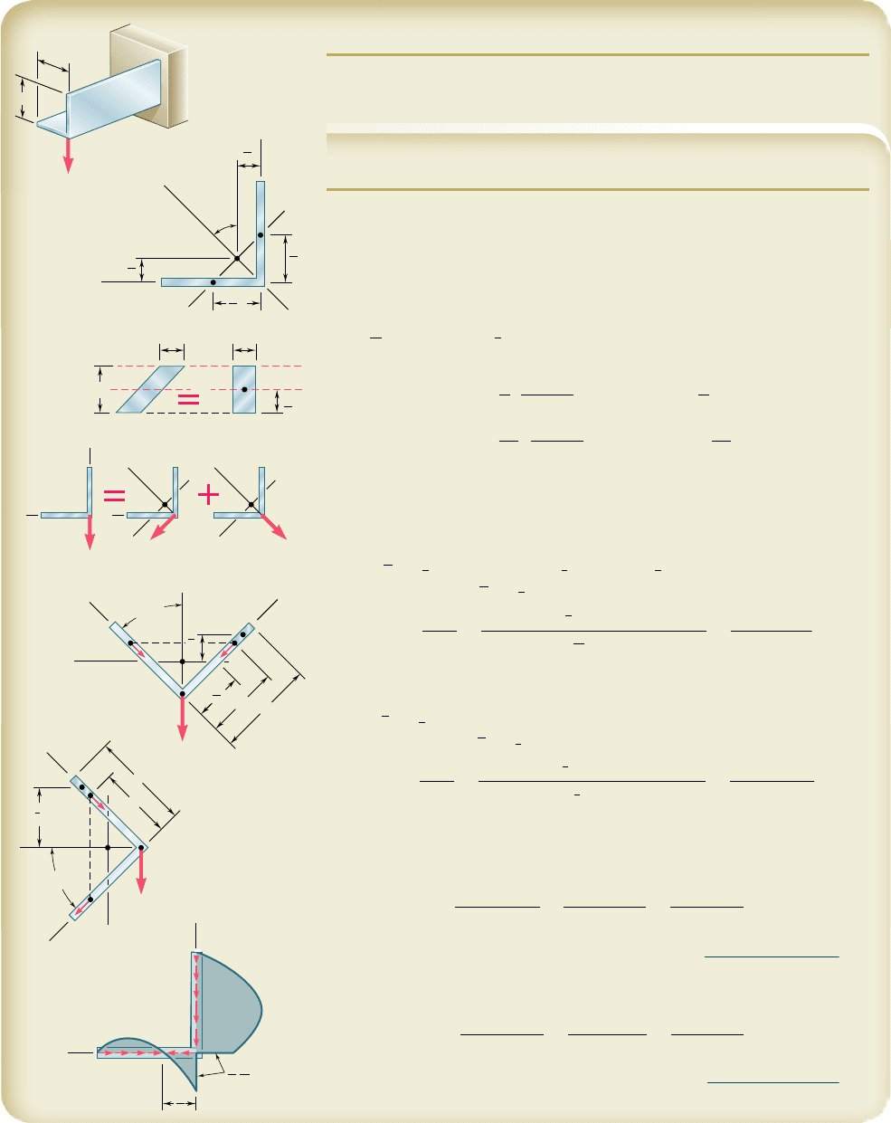
SAMPLE PROBLEM 6.6
Determine the distribution of shearing stresses in the thin-walled angle
shape DE of uniform thickness t for the loading shown.
a
a
D
E
P
B
y
y'
z
z'
C
A
O
a
45
1
2
a
1
2
a
4
a
4
1
2
h
h
bb
nnn
mm m
n
z'
z'
y'
y'
A
B
O
V P
y
z
C
O
O
V
z'
P cos 45
V
y'
P cos 45
C
z
'
y'
y'
2
1
z
1
1
B
e
a
a
y
O
A
f
V
y'
P cos 45
y
C
45
z'
z'
y
'
a
z
2
2
B
e
O
A
f
V
z'
P cos 45
y
y
C
45
B
A
z
O
y
a
3
3
4
P
at
SOLUTION
Shear Center. We recall from Sec. 6.9 that the shear center of the
cross section of a thin-walled angle shape is located at its corner. Since the
load P is applied at D, it causes bending but no twisting of the shape.
Principal Axes. We locate the centroid C of a given cross section AOB.
Since the y9 axis is an axis of symmetry, the y9 and z9 axes are the principal
centroidal axes of the section. We recall that for the parallelogram shown
I
nn
5
1
12
bh
3
and I
mm
5
1
3
bh
3
. Considering each leg of the section as a paral-
lelogram, we now determine the centroidal moments of inertia I
y9
and I
z9
:
I
y¿
5 2
c
1
3
a
t
cos 45°
b
1a cos 45°2
3
d
5
1
3
ta
3
I
z¿
5 2
c
1
12
a
t
cos 45°
b
1a cos 45°2
3
d
5
1
12
ta
3
Superposition. The shear V in the section is equal to the load P. We
resolve it into components parallel to the principal axes.
Shearing Stresses Due to V
y 9
. We determine the shearing stress at
point e of coordinate y:
y
¿ 5
1
2
1a 1 y2 cos 45° 2
1
2
a cos 45° 5
1
2
y cos 45°
Q 5 t1a 2 y2
y¿ 5
1
2
t1a 2 y2y cos 45°
t
1
5
V
y¿
Q
I
z¿
t
5
1P cos 45°23
1
2
t1a 2 y2y cos 45°4
1
1
12
ta
3
2
t
5
3P1a 2 y2
y
ta
3
The shearing stress at point f is represented by a similar function of z.
Shearing Stresses Due to V
z9
. We again consider point e:
z¿ 5
1
2
1a 1 y2 cos 45°
Q 5 1a 2 y2
tz¿ 5
1
2
1a
2
2 y
2
2t cos 45°
t
2
5
V
z¿
Q
I
y¿
t
5
1P cos 45°23
1
2
1a
2
2 y
2
2t cos 45°4
1
1
3
ta
3
2t
5
3P1a
2
2 y
2
2
4ta
3
The shearing stress at point f is represented by a similar function of z.
Combined Stresses. Along the Vertical Leg. The shearing stress at
point e is
t
e
5 t
2
1 t
1
5
3P1a
2
2 y
2
2
4
ta
3
1
3P1a 2 y2
y
ta
3
5
3P1a 2 y
2
4
ta
3
31a 1 y21 4y4
t
e
5
3P
1
a 2 y
21
a 1 5y
2
4
ta
3
◀
Along the Horizontal Leg. The shearing stress at point f is
t
f
5 t
2
2 t
1
5
3P1a
2
2 z
2
2
4
ta
3
2
3P1a 2 z2
z
ta
3
5
3P1a 2 z
2
4
ta
3
31a 1 z22 4z4
t
f
5
3P
1
a 2 z
21
a 2 3z
2
4
ta
3
◀
bee80288_ch06_380-435.indd Page 422 11/13/10 12:26:09 AM user-f499bee80288_ch06_380-435.indd Page 422 11/13/10 12:26:09 AM user-f499 /Users/user-f499/Desktop/Temp Work/Don't Delete Job/MHDQ251:Beer:201/ch06/Users/user-f499/Desktop/Temp Work/Don't Delete Job/MHDQ251:Beer:201/ch06
Apago PDF Enhancer
PROBLEMS
423
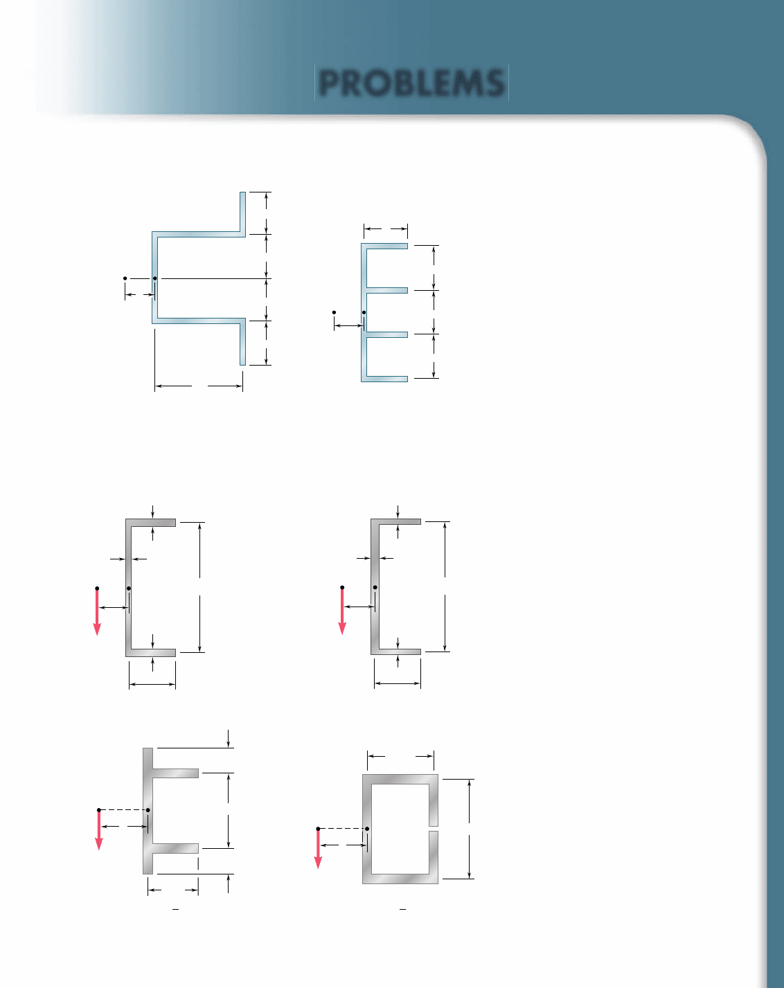
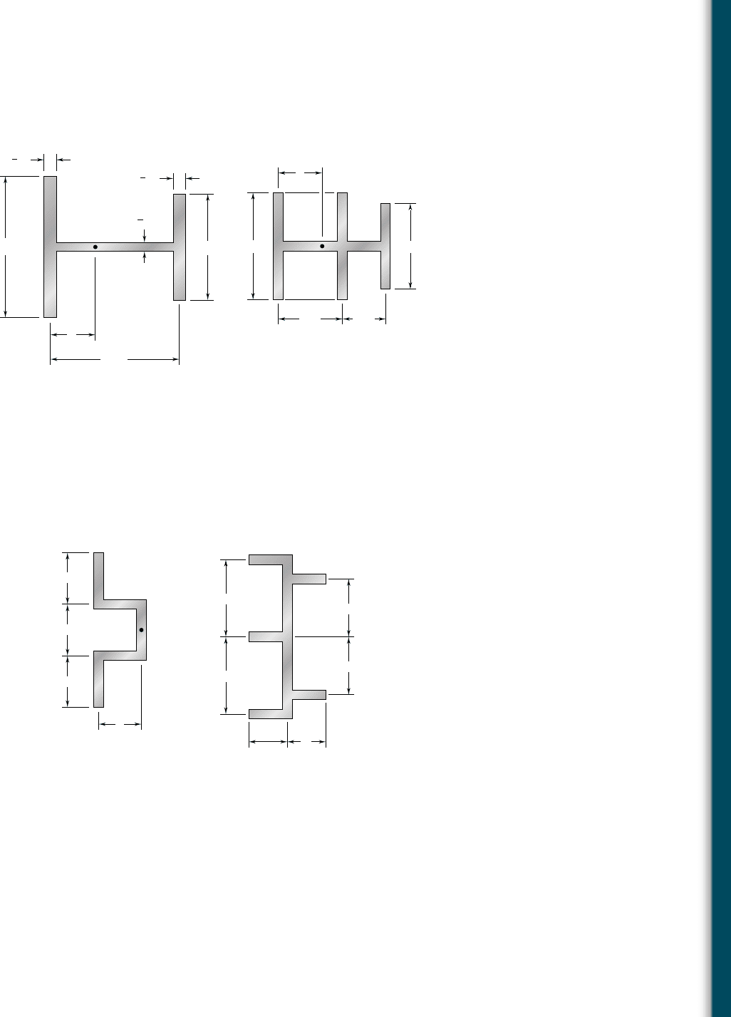
6.63 through 6.66 An extruded beam has the cross section shown.
Determine (a) the location of the shear center O, (b) the distribu-
tion of the shearing stresses caused by the vertical shearing force
V shown applied at O.
6.61 and 6.62 Determine the location of the shear center O of a thin-
walled beam of uniform thickness having the cross section shown.
2a
E
F
e
O
A
D
B
a
a
a
a
G
Fig. P6.61
e
E
F
O
A
a
D
HJ
B
a
a
a
G
Fig. P6.62
Fig. P6.63
72 mm
B
O
D
C
E
192 mm
A
e
12 mm
12 mm
6 mm
V
⫽ 110 kN
72 mm
B
O
D
C
E
192 mm
A
e
6 mm
6 mm
12 mm
V
⫽ 110 kN
Fig. P6.64
4.0 in.
6.0 in.
A
DB
G
EF
in.t ⫽
1
8
V
⫽ 2.75 kips
O
e
Fig. P6.66
V
⫽ 2.75 kips
in.t ⫽
1
8
4 in.
2 in.
6 in.
A
B
D
O
E
G
e
F
2 in.
Fig. P6.65
bee80288_ch06_380-435.indd Page 423 10/29/10 8:36:12 PM user-f499bee80288_ch06_380-435.indd Page 423 10/29/10 8:36:12 PM user-f499 /Volumes/201/MHDQ251/bee80288_disk1of1/0073380288/bee80288_pagefiles/Volumes/201/MHDQ251/bee80288_disk1of1/0073380288/bee80288_pagefiles
Apago PDF Enhancer
424
Shearing Stresses in Beams
and Thin-Walled Members
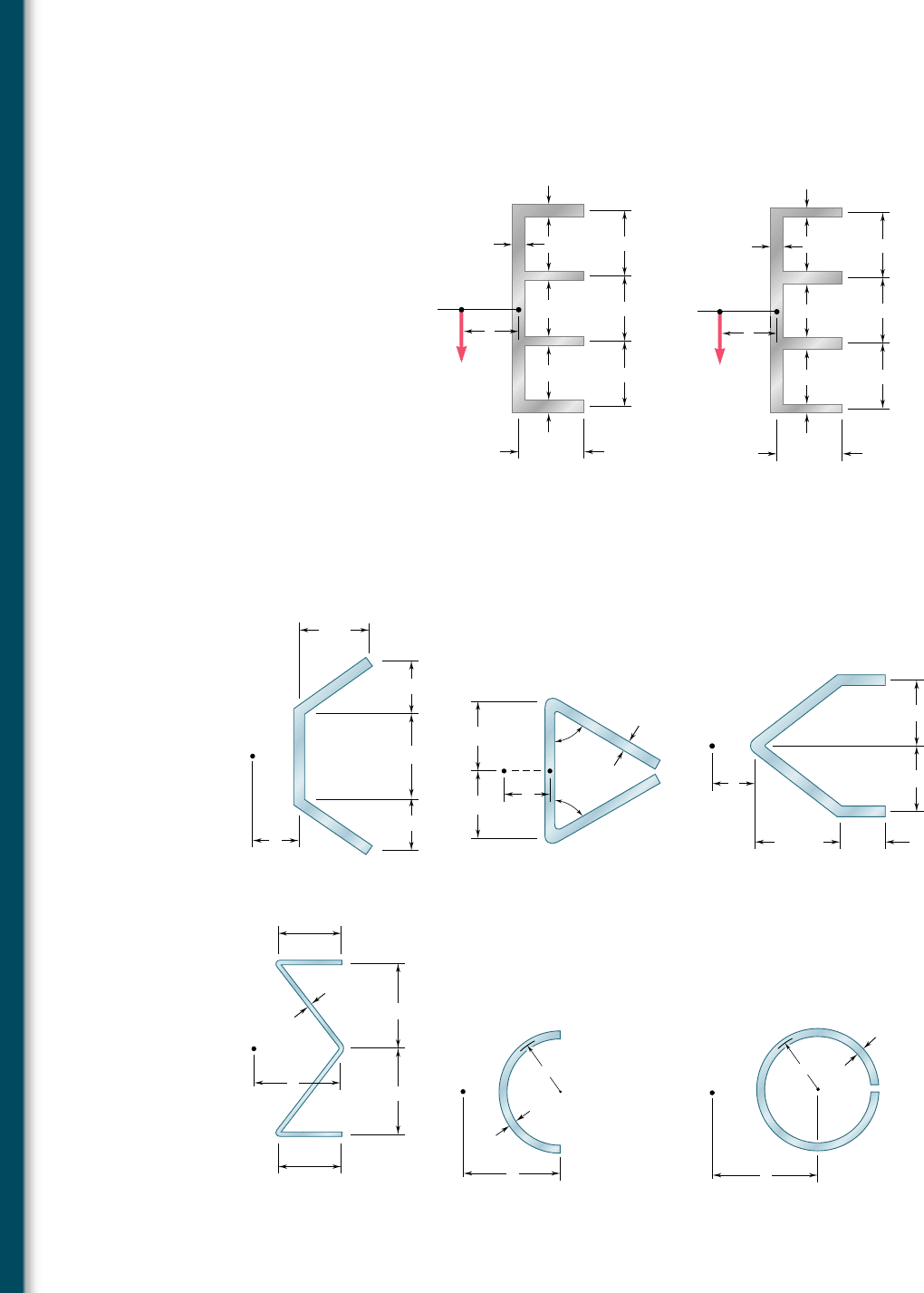
6.69 through 6.74 Determine the location of the shear center O
of a thin-walled beam of uniform thickness having the cross section
shown.
A
E
e
O
D
B
5 in.
4 in.
3 in.
3 in.
Fig. P6.69
60 mm
A
e
B
EF
D
O
60 mm
80 mm
40 mm
Fig. P6.71
E
60
60
F
e
O
A
D
B
35 mm
35 mm
6 mm
Fig. P6.70
E
2 in.
2 in.
0.1 in.
1.5 in.
1.5 in.
F
e
O
A
D
B
Fig. P6.72
t
e
O
A
a
B
Fig. P6.73
e
O
A
at
B
Fig. P6.74
6.67 through 6.68 An extruded beam has the cross section shown.
Determine (a) the location of the shear center O, (b) the distribu-
tion of the shearing stresses caused by the vertical shearing force
V shown applied at O.
O
z
6 mm
6 mm
30 m
m
30 m
m
30 m
m
6 mm
30 mm
4 mm
4 mm
A
B
DE
F
e
H
J
G
V 35 kN
I
z
1.149 10
6
mm
4
Fig. P6.67
I
z
0.933 10
6
mm
4
O
z
4 mm
6 mm
30 m
m
30 m
m
30 m
m
4 mm
30 mm
6 mm
6 mm
A
B
DE
F
e
H
J
G
V 35 kN
Fig. P6.68
bee80288_ch06_380-435.indd Page 424 11/13/10 12:26:25 AM user-f499bee80288_ch06_380-435.indd Page 424 11/13/10 12:26:25 AM user-f499 /Users/user-f499/Desktop/Temp Work/Don't Delete Job/MHDQ251:Beer:201/ch06/Users/user-f499/Desktop/Temp Work/Don't Delete Job/MHDQ251:Beer:201/ch06
Apago PDF Enhancer
425
Problems
6.77 and 6.78 A thin-walled beam of uniform thickness has the cross
section shown. Determine the dimension b for which the shear
center O of the cross section is located at the point indicated.
6.79 For the angle shape and loading of Sample Prob. 6.6, check that
e q dz 5 0 along the horizontal leg of the angle and e q dy 5 P
along its vertical leg.
6.80 For the angle shape and loading of Sample Prob. 6.6, (a) determine
the points where the shearing stress is maximum and the corre-
sponding values of the stress, (b) verify that the points obtained are
located on the neutral axis corresponding to the given loading.
Fig. P6.77 Fig. P6.78
30 mm
b
A
F
J
B
D
G
O
H
E
K
60 mm
60 mm
45 mm
45 mm
60 mm
60 mm
60 mm
A
B
D
O
E
F
G
b
6.75 and 6.76 A thin-walled beam has the cross section shown.
Determine the location of the shear center O of the cross section.
Fig. P6.75
5 in.
3 in.
B
O
e
AD
E
G
F
2 in.
4 in.
Fig. P6.76
e
8 in.
6 in.
8 in.
O
in.
1
2
in.
3
4
in.
3
4
bee80288_ch06_380-435.indd Page 425 10/28/10 8:03:55 PM user-f499bee80288_ch06_380-435.indd Page 425 10/28/10 8:03:55 PM user-f499 /Volumes/201/MHDQ251/bee80288_disk1of1/0073380288/bee80288_pagefiles/Volumes/201/MHDQ251/bee80288_disk1of1/0073380288/bee80288_pagefiles
Apago PDF Enhancer
426
Shearing Stresses in Beams
and Thin-Walled Members
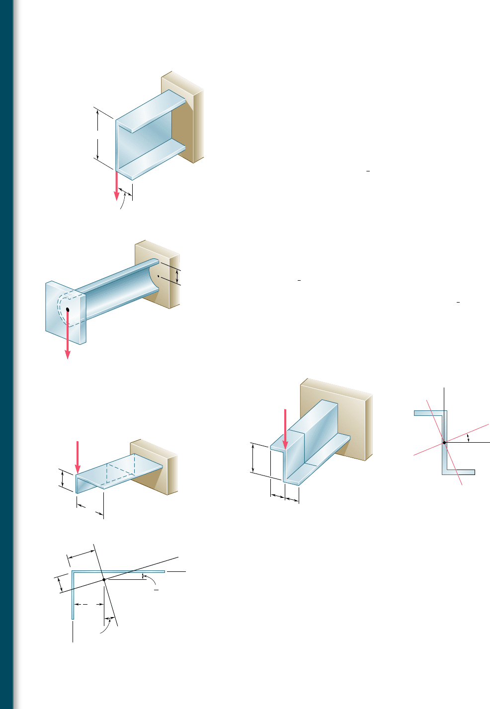
*6.81 A steel plate, 160 mm wide and 8 mm thick, is bent to form the
channel shown. Knowing that the vertical load P acts at a point in
the midplane of the web of the channel, determine (a) the torque
T that would cause the channel to twist in the same way that it
does under the load P, (b) the maximum shearing stress in the
channel caused by the load P.
*6.82 Solve Prob. 6.81, assuming that a 6-mm-thick plate is bent to form
the channel shown.
*6.83 The cantilever beam AB, consisting of half of a thin-walled pipe
of 1.25-in. mean radius and
3
8
-in. wall thickness, is subjected to a
500-lb vertical load. Knowing that the line of action of the load
passes through the centroid C of the cross section of the beam,
determine (a) the equivalent force-couple system at the shear cen-
ter of the cross section, (b) the maximum shearing stress in the
beam. (Hint: The shear center O of this cross section was shown
in Prob. 6.73 to be located twice as far from its vertical diameter
as its centroid C.)
*6.84 Solve Prob. 6.83, assuming that the thickness of the beam is
reduced to
1
4
in.
*6.85 The cantilever beam shown consists of a Z shape of
1
4
-in. thickness.
For the given loading, determine the distribution of the shearing
stresses along line A9B9 in the upper horizontal leg of the Z shape.
The x9 and y9 axes are the principal centroidal axes of the cross
section and the corresponding moments of inertia are I
x9
5 166.3 in
4
and I
y9
5 13.61 in
4
.
12 in.
6 in.
6 in.
22.5
A'
A'
B'
B'
C'
y
x
x
'
y'
A
B
D'
D'
E'
E'
E
D
3 kips
(a)(b)
Fig. P6.85
*6.86 For the cantilever beam and loading of Prob. 6.85, determine the
distribution of the shearing stress along line B9D9 in the vertical
web of the Z shape.
*6.87 Determine the distribution of the shearing stresses along line D9B9
in the horizontal leg of the angle shape for the loading shown. The
x9 and y9 axes are the principal centroidal axes of the cross section.
*6.88 For the angle shape and loading of Prob. 6.87, determine the distri-
bution of the shearing stresses along line D9A9 in the vertical leg.
2a
15.8
I
x'
1.428ta
3
I
y'
0.1557ta
3
0.342a
0.596a
a
A
B
B'
D'
D
A'
A'
D'
x'
y'
x
y
C'
B'
P
a
2
3
a
6
Fig. P6.87
P 15 kN
100 mm
B
D
E
30 mm
A
Fig. P6.81
1.25 in.
500 lb
A
B
C
Fig. P6.83
bee80288_ch06_380-435.indd Page 426 10/28/10 8:03:55 PM user-f499bee80288_ch06_380-435.indd Page 426 10/28/10 8:03:55 PM user-f499 /Volumes/201/MHDQ251/bee80288_disk1of1/0073380288/bee80288_pagefiles/Volumes/201/MHDQ251/bee80288_disk1of1/0073380288/bee80288_pagefiles
