Beer F.P., Johnston E.R., DeWolf J.T., Mazurek D.F. Mechanics of Materials
Подождите немного. Документ загружается.

Apago PDF Enhancer
SAMPLE PROBLEM 7.1
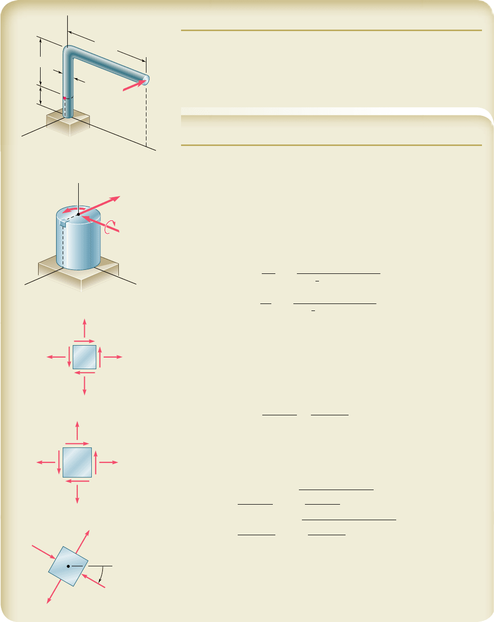
A single horizontal force P of magnitude 150 lb is applied to end D of lever
ABD. Knowing that portion AB of the lever has a diameter of 1.2 in., deter-
mine (a) the normal and shearing stresses on an element located at point H
and having sides parallel to the x and y axes, (b) the principal planes and the
principal stresses at point H.
SOLUTION
Force-Couple System. We replace the force P by an equivalent force-
couple system at the center C of the transverse section containing point H:
P 5 150 lb
T 5
1
150 lb
21
18 in.
2
5 2.7 kip ? in.
M
x
5
1
150 lb
21
10 in.
2
5 1.5 kip ? in.
a. Stresses S
x
, S
y
, T
xy
at Point H. Using the sign convention shown
in Fig. 7.2, we determine the sense and the sign of each stress component
by carefully examining the sketch of the force-couple system at point C:
s
x
5 0 s
y
51
Mc
I
51
1
1.5 kip ? in.
21
0.6 in.
2
1
4
p
1
0.6 in.
2
4
s
y
518.84 ksib
t
xy
51
Tc
J
51
1
2.7 kip ? in.
21
0.6 in.
2
1
2
p
1
0.6 in.
2
4
t
xy
517.96 ksib
We note that the shearing force P does not cause any shearing stress at
point H.
b. Principal Planes and Principal Stresses. Substituting the values of
the stress components into Eq. (7.12), we determine the orientation of the
principal planes:
tan 2u
p
5
2t
xy
s
x
2 s
y
5
217.96
2
0 2 8.84
521.80
2 u
p
5261.0°and180° 2 61.0° 51119°
u
p
5230.5°and159.5°b
Substituting into Eq. (7.14), we determine the magnitudes of the principal
stresses:
s
max, min
5
s
x
1 s
y
2
6
B
a
s
x
2 s
y
2
b
2
1 t
xy
2
5
0 1 8.84
2
6
B
a
0 2 8.84
2
b
2
1 17.962
2
514.42 6 9.10
s
max
5113.52 ksib
s
m
i
n
524.68 ksib
Considering face ab of the element shown, we make u
p
5 230.58 in Eq. (7.5)
and find s
x9
5 24.68 ksi. We conclude that the principal stresses are as
shown.
M
x
1.5 kip · in.
T 2.7 kip · in.
H
x
z
y
C
P 150 lb
y
x
xy
xy
7.96 ksi
y
8.84 ksi
x
0
p
30.5
max
13.52 ksi
min
4.68 ksi
H
a
b
18 in.
1.2 in.
H
A
D
B
y
z
x
10 in.
4 in.
P
447
bee80288_ch07_436-511.indd Page 447 11/18/10 7:33:25 PM user-f499bee80288_ch07_436-511.indd Page 447 11/18/10 7:33:25 PM user-f499 /Users/user-f499/Desktop/Temp Work/Don't Delete Job/MHDQ251:Beer:201/ch07/Users/user-f499/Desktop/Temp Work/Don't Delete Job/MHDQ251:Beer:201/ch07
Apago PDF Enhancer
PROBLEMS
448
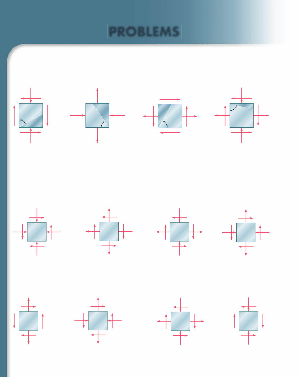
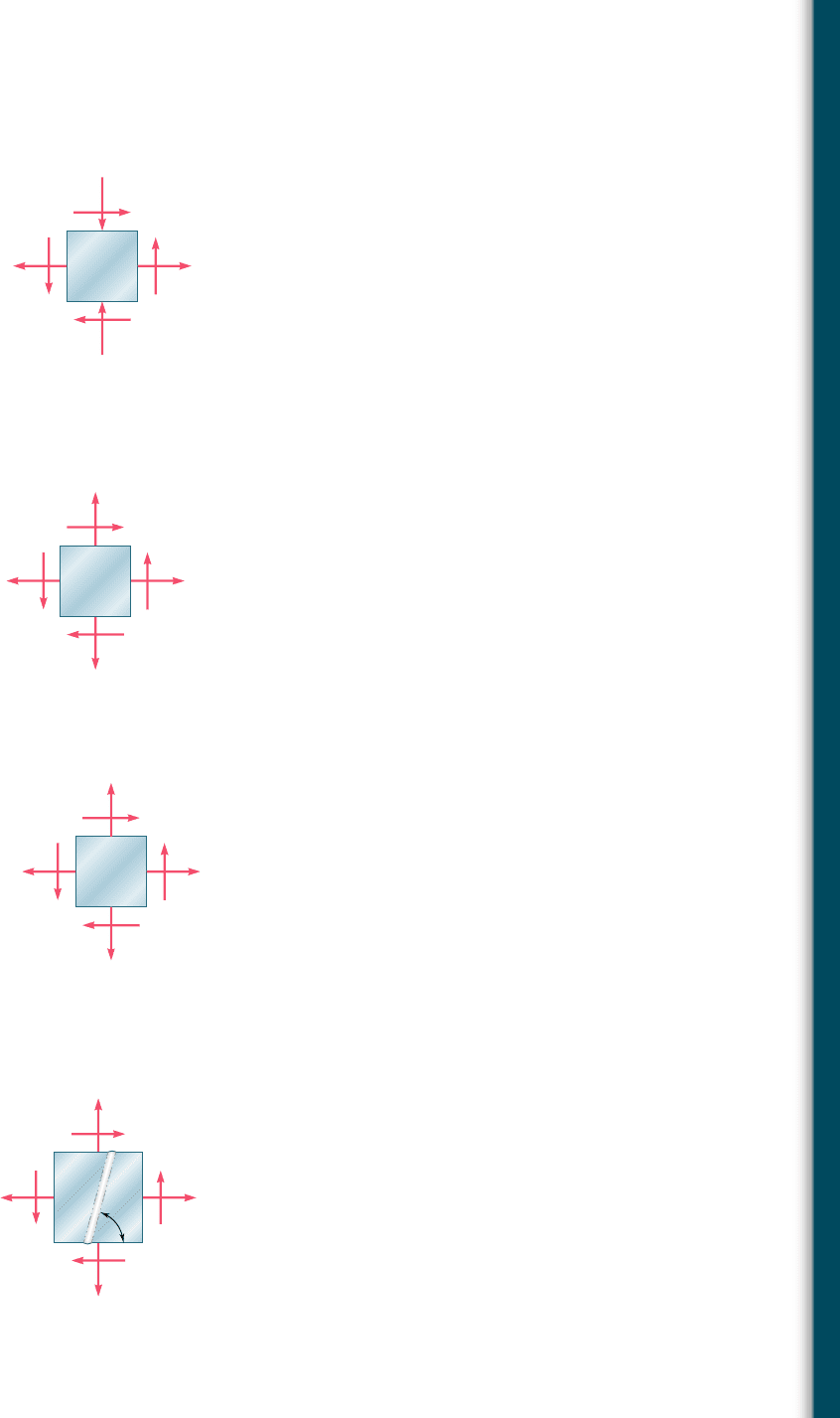
7.5 through 7.8 For the given state of stress, determine (a) the
principal planes, (b) the principal stresses.
7.9 through 7.12 For the given state of stress, determine (a) the
orientation of the planes of maximum in-plane shearing stress,
(b) the maximum in-plane shearing stress, (c) the corresponding
normal stress.
7.1 through 7.4 For the given state of stress, determine the normal
and shearing stresses exerted on the oblique face of the shaded tri-
angular element shown. Use a method of analysis based on the equi-
librium of that element, as was done in the derivations of Sec. 7.2.
10 ksi
15 ksi
60
Fig. P7.1
80 MPa
40 MP
a
55
Fig. P7.2
6 ksi
60
5 ksi
Fig. P7.3
45 MPa
27 MP
a
75
18 MPa
Fig. P7.4
40 MPa
35 MPa
60 MP
a
Fig. P7.5 and P7.9
12 ksi
15 ksi
4 ksi
Fig. P7.7 and P7.11
12 ksi
5 ksi
8 ksi
Fig. P7.8 and P7.12
50 MPa
10 MP
a
15 MPa
Fig. P7.6 and P7.10
7.13 through 7.16 For the given state of stress, determine the nor-
mal and shearing stresses after the element shown has been rotated
through (a) 258 clockwise, (b) 108 counterclockwise.
90 MPa
30 MPa
60 MP
a
Fig. P7.14
80 MPa
50 MP
a
Fig. P7.16
12 ksi
6 ksi
8 ksi
Fig. P7.15
8 ksi
5 ksi
Fig. P7.13
bee80288_ch07_436-511.indd Page 448 10/30/10 1:37:49 AM user-f499bee80288_ch07_436-511.indd Page 448 10/30/10 1:37:49 AM user-f499 /Users/user-f499/Desktop/Temp Work/Don't Delete Job/MHDQ251:Beer:201/ch07/Users/user-f499/Desktop/Temp Work/Don't Delete Job/MHDQ251:Beer:201/ch07
Apago PDF Enhancer
449
Problems
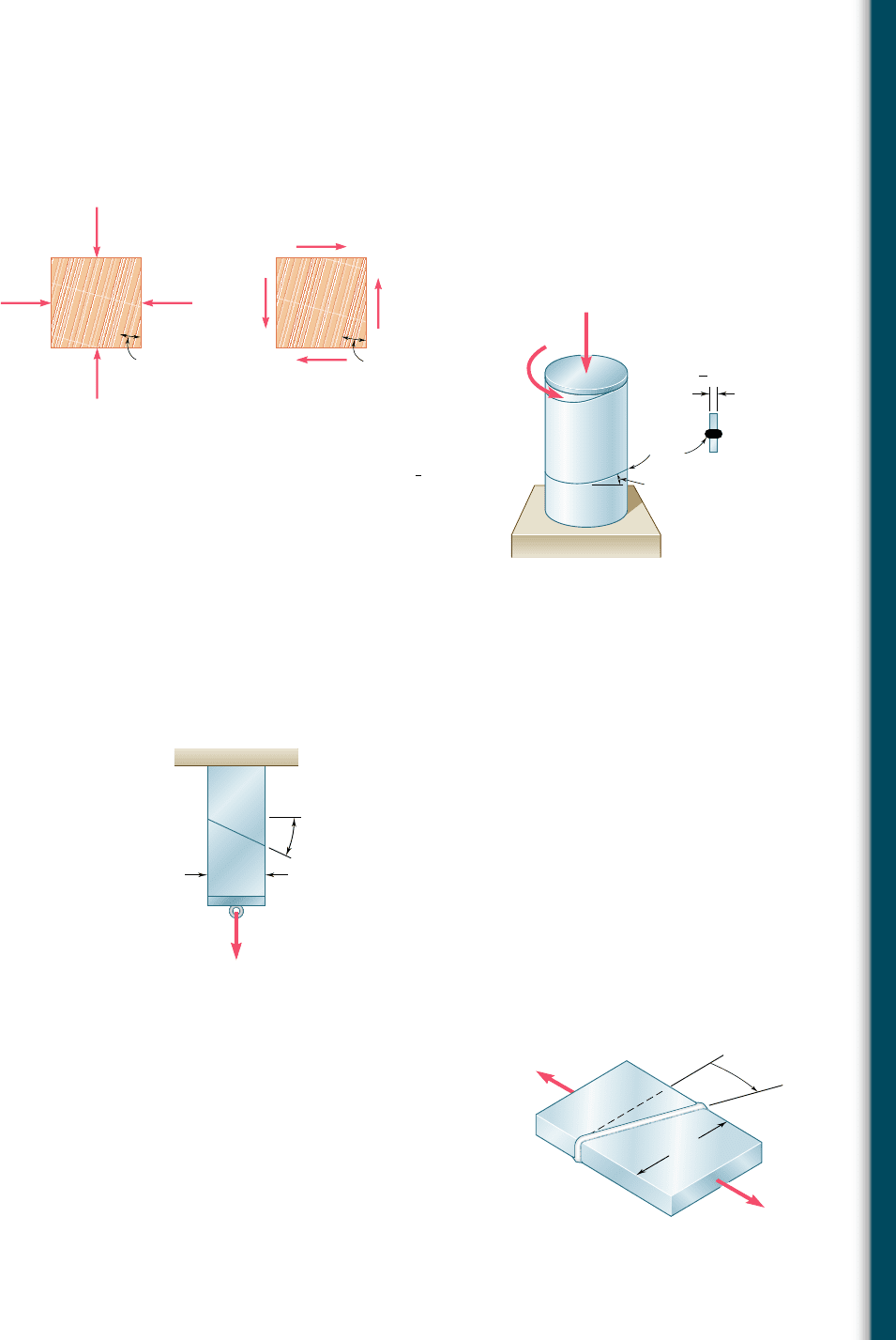
7.19 A steel pipe of 12-in. outer diameter is fabricated from
1
4
-in.-thick
plate by welding along a helix that forms an angle of 22.58 with a
plane perpendicular to the axis of the pipe. Knowing that a 40-kip
axial force P and an 80-kip ? in. torque T, each directed as shown,
are applied to the pipe, determine s and t in directions, respec-
tively, normal and tangential to the weld.
7.20 Two members of uniform cross section 50 3 80 mm are glued
together along plane a-a that forms an angle of 258 with the hori-
zontal. Knowing that the allowable stresses for the glued joint are
s 5 800 kPa and t 5 600 kPa, determine the largest centric load
P that can be applied.
7.17 and 7.18 The grain of a wooden member forms an angle of 158
with the vertical. For the state of stress shown, determine (a) the
in-plane shearing stress parallel to the grain, (b) the normal stress
perpendicular to the grain.
400 psi
15⬚
Fig. P7.18
1.6 MPa
4 MP
a
15⬚
Fig. P7.17
22.5°
in.
1
4
P
T
Weld
Fig. P7.19
P
a
25⬚
50 mm
a
Fig. P7.20
100 kN

100 kN
80 mm
Fig. P7.21 and P7.22
7.21 Two steel plates of uniform cross section 10 3 80 mm are welded
together as shown. Knowing that centric 100-kN forces are applied
to the welded plates and that b 5 258, determine (a) the in-plane
shearing stress parallel to the weld, (b) the normal stress perpen-
dicular to the weld.
7.22 Two steel plates of uniform cross section 10 3 80 mm are welded
together as shown. Knowing that centric 100-kN forces are applied
to the welded plates and that the in-plane shearing stress parallel
to the weld is 30 MPa, determine (a) the angle b, (b) the corre-
sponding normal stress perpendicular to the weld.
bee80288_ch07_436-511.indd Page 449 11/19/10 2:56:13 PM user-f499bee80288_ch07_436-511.indd Page 449 11/19/10 2:56:13 PM user-f499 /Users/user-f499/Desktop/Temp Work/Don't Delete Job/MHDQ251:Beer:201/ch07/Users/user-f499/Desktop/Temp Work/Don't Delete Job/MHDQ251:Beer:201/ch07
Apago PDF Enhancer
450
Transformations of Stress and Strain
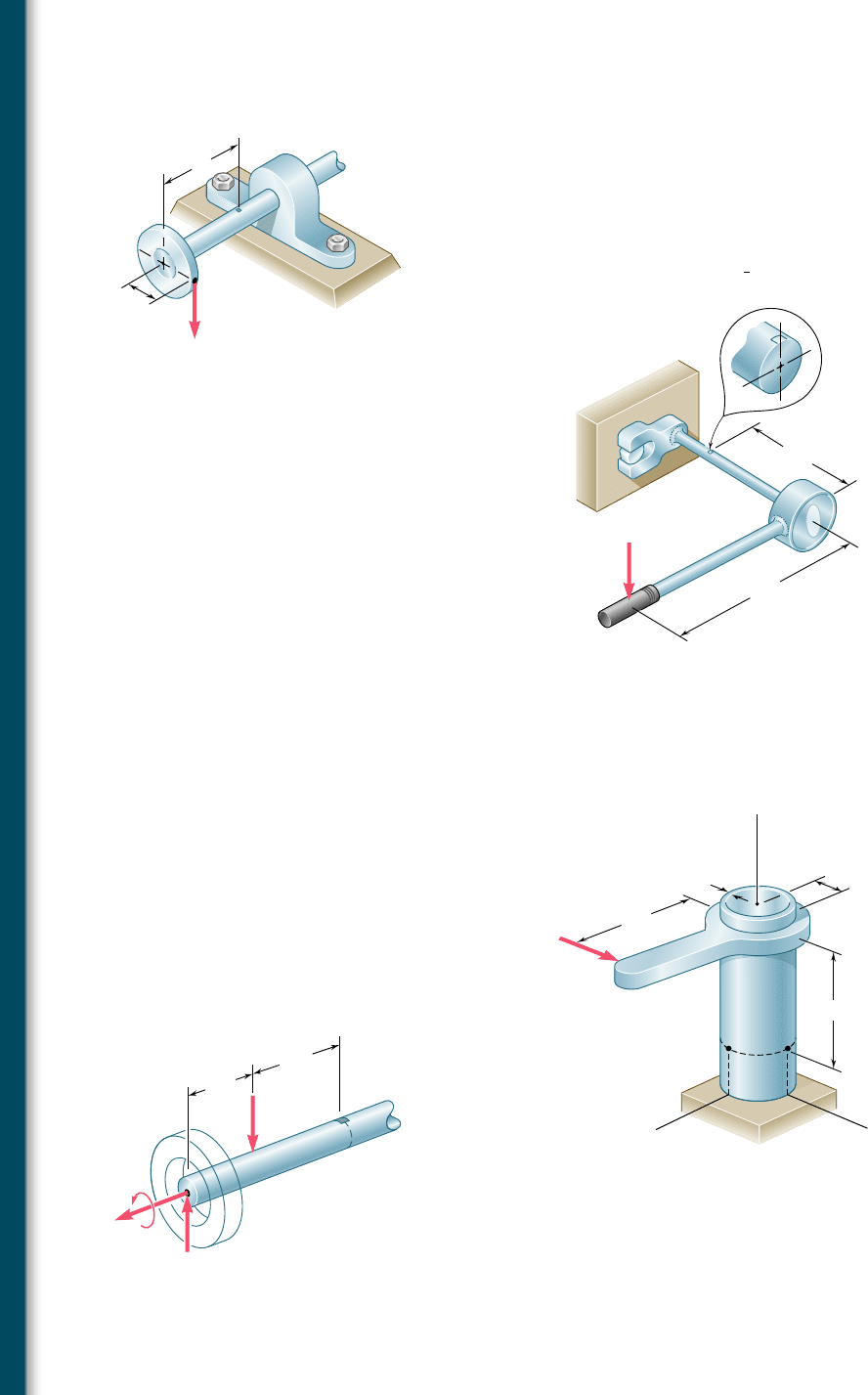
7.25 The steel pipe AB has a 102-mm outer diameter and a 6-mm wall
thickness. Knowing that arm CD is rigidly attached to the pipe,
determine the principal stresses and the maximum shearing stress
at point K.
7.23 A 400-lb vertical force is applied at D to a gear attached to the
solid 1-in. diameter shaft AB. Determine the principal stresses and
the maximum shearing stress at point H located as shown on top
of the shaft.
7.2 4 A mechanic uses a crowfoot wrench to loosen a bolt at E. Knowing
that the mechanic applies a vertical 24-lb force at A, determine the
principal stresses and the maximum shearing stress at point H
located as shown on top of the
3
4
-in. diameter shaft.
6 in.
2 in.
D
A
B
H
C
400 lb
Fig. P7.23
24 lb
10 in.
6 in.
E
B
A
H
Fig. P7.24
200 mm
6 mm
150 mm
51 mm
z
x
T
A
y
D
KH
10 kN
A
B
C
Fig. P7.25
7.26 The axle of an automobile is acted upon by the forces and couple
shown. Knowing that the diameter of the solid axle is 32 mm,
determine (a) the principal planes and principal stresses at point
H located on top of the axle, (b) the maximum shearing stress at
the same point.
3 kN
3 kN
350 N · m
0.15 m
H
0.2 m
Fig. P7.26
bee80288_ch07_436-511.indd Page 450 11/17/10 11:10:41 PM user-f499bee80288_ch07_436-511.indd Page 450 11/17/10 11:10:41 PM user-f499 /Users/user-f499/Desktop/Temp Work/Don't Delete Job/MHDQ251:Beer:201/ch07/Users/user-f499/Desktop/Temp Work/Don't Delete Job/MHDQ251:Beer:201/ch07
Apago PDF Enhancer
451
Problems
7.30 For the state of plane stress shown, determine (a) the value of t
xy
for which the in-plane shearing stress parallel to the weld is zero,
(b) the corresponding principal stresses.
7.27 For the state of plane stress shown, determine (a) the largest value
of t
xy
for which the maximum in-plane shearing stress is equal to
or less than 12 ksi, (b) the corresponding principal stresses.
8 ksi
10 ksi
xy
Fig. P7.27
60 MP
a
20 MPa
y
Fig. P7.28
15 ksi
8 ksi
x
Fig. P7.29
xy
12 MP
a
2 MPa
75
Fig. P7.30
7.28 For the state of plane stress shown, determine the largest value of
s
y
for which the maximum in-plane shearing stress is equal to or
less than 75 MPa.
7.29 Determine the range of values of s
x
for which the maximum in-
plane shearing stress is equal to or less than 10 ksi.
bee80288_ch07_436-511.indd Page 451 10/30/10 1:38:45 AM user-f499bee80288_ch07_436-511.indd Page 451 10/30/10 1:38:45 AM user-f499 /Users/user-f499/Desktop/Temp Work/Don't Delete Job/MHDQ251:Beer:201/ch07/Users/user-f499/Desktop/Temp Work/Don't Delete Job/MHDQ251:Beer:201/ch07
Apago PDF Enhancer
452
Transformations of Stress and Strain
7.4 MOHR’S CIRCLE FOR PLANE STRESS
The circle used in the preceding section to derive some of the basic
formulas relating to the transformation of plane stress was first
introduced by the German engineer Otto Mohr (1835–1918) and is
known as Mohr’s circle for plane stress. As you will see presently,
this circle can be used to obtain an alternative method for the solu-
tion of the various problems considered in Secs. 7.2 and 7.3. This
method is based on simple geometric considerations and does not
require the use of specialized formulas. While originally designed
for graphical solutions, it lends itself well to the use of a
calculator.
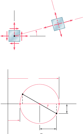
Consider a square element of a material subjected to plane
stress (Fig. 7.15a), and let s
x
, s
y
, and t
xy
be the components of the
stress exerted on the element. We plot a point X of coordinates s
x
and 2t
xy
, and a point Y of coordinates s
y
and 1t
xy
(Fig. 7.15b). If
t
xy
is positive, as assumed in Fig. 7.15a, point X is located below the
s axis and point Y above, as shown in Fig. 7.15b. If t
xy
is negative,
X is located above the s axis and Y below. Joining X and Y by a
straight line, we define the point C of intersection of line XY with
the s axis and draw the circle of center C and diameter XY. Noting
that the abscissa of C and the radius of the circle are respectively
equal to the quantities s
ave
and R defined by Eqs. (7.10), we con-
clude that the circle obtained is Mohr’s circle for plane stress. Thus
the abscissas of points A and B where the circle intersects the s axis
represent respectively the principal stresses s
max
and s
min
at the
point considered.
We also note that, since tan (XCA) 5 2t
xy
y(s
x
2 s
y
), the angle
XCA is equal in magnitude to one of the angles 2u
p
that satisfy Eq.
(7.12). Thus, the angle u
p
that defines in Fig. 7.15a the orientation
of the principal plane corresponding to point A in Fig. 7.15b can be
obtained by dividing in half the angle XCA measured on Mohr’s cir-
cle. We further observe that if s
x
. s
y
and t
xy
. 0, as in the case
considered here, the rotation that brings CX into CA is counterclock-
wise. But, in that case, the angle u
p
obtained from Eq. (7.12) and
defining the direction of the normal Oa to the principal plane is
positive; thus, the rotation bringing Ox into Oa is also counterclock-
wise. We conclude that the senses of rotation in both parts of Fig. 7.15
are the same; if a counterclockwise rotation through 2u
p
is required
to bring CX into CA on Mohr’s circle, a counterclockwise rotation
through u
p
will bring Ox into Oa in Fig. 7.15a.†
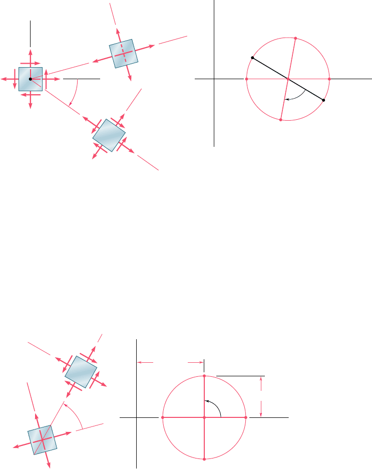
Since Mohr’s circle is uniquely defined, the same circle can be
obtained by considering the stress components s
x9
, s
y9
, and t
x9y9
, cor-
responding to the x9 and y9 axes shown in Fig. 7.16a. The point X9 of
coordinates s
x9
and 2t
x9y9
, and the point Y9 of coordinates s
y9
and
1t
x9y9
, are therefore located on Mohr’s circle, and the angle X9CA in
Fig. 7.16b must be equal to twice the angle x9Oa in Fig. 7.16a. Since,
as noted before, the angle XCA is twice the angle xOa, it follows that
†This is due to the fact that we are using the circle of Fig 7.8 rather than the circle of
Fig. 7.7 as Mohr’s circle.
p
y
max
max
min
min
x
xy
O
x
a
b
y
(a)
Fig. 7.15 Mohr’s circle.
max
min
x
y
(b)
O
BA
Y ,
C
(
)
y
xy
(
2
p
)
X ,
x
xy
xy
(
)
1
2
bee80288_ch07_436-511.indd Page 452 11/17/10 11:10:50 PM user-f499bee80288_ch07_436-511.indd Page 452 11/17/10 11:10:50 PM user-f499 /Users/user-f499/Desktop/Temp Work/Don't Delete Job/MHDQ251:Beer:201/ch07/Users/user-f499/Desktop/Temp Work/Don't Delete Job/MHDQ251:Beer:201/ch07
Apago PDF Enhancer
453
the angle XCX9 in Fig. 7.16b is twice the angle xOx9 in Fig. 7.16a. Thus
the diameter X9Y9 defining the normal and shearing stresses s
x9
, s
y9
,
and t
x9y9
can be obtained by rotating the diameter XY through an angle
equal to twice the angle u formed by the x9and x axes in Fig. 7.16a.
We note that the rotation that brings the diameter XY into the diameter
X9Y9 in Fig. 7.16b has the same sense as the rotation that brings the
xy axes into the x9y9 axes in Fig. 7.16a.
7.4 Mohr’s Circle for Plane Stress
y
x
xy
O
y'
x'
y'
x'
max
min
x'y'
x
2
a
b
y
(a)(b)
Y'
X
ABOC
Y
,
y'
x'y
(
'
)
X' ,
x'
x'y
(
'
)
Fig. 7.16
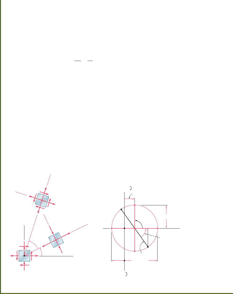
The property we have just indicated can be used to verify the
fact that the planes of maximum shearing stress are at 458 to the
principal planes. Indeed, we recall that points D and E on Mohr’s
circle correspond to the planes of maximum shearing stress, while A
and B correspond to the principal planes (Fig. 7.17b). Since the
diameters AB and DE of Mohr’s circle are at 908 to each other, it
follows that the faces of the corresponding elements are at 458 to
each other (Fig. 7.17a).
ave
'
'
'
(a)(b)
O
O
BC A
D
E
max
min
max
max
45
90
b
d
a
e
Fig. 7.17
bee80288_ch07_436-511.indd Page 453 10/30/10 1:38:56 AM user-f499bee80288_ch07_436-511.indd Page 453 10/30/10 1:38:56 AM user-f499 /Users/user-f499/Desktop/Temp Work/Don't Delete Job/MHDQ251:Beer:201/ch07/Users/user-f499/Desktop/Temp Work/Don't Delete Job/MHDQ251:Beer:201/ch07
Apago PDF Enhancer
454
Transformations of Stress and Strain
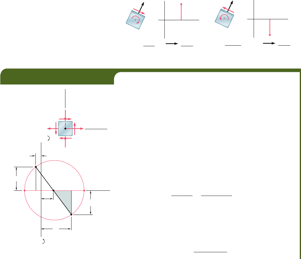
The construction of Mohr’s circle for plane stress is greatly simpli-
fied if we consider separately each face of the element used to define
the stress components. From Figs. 7.15 and 7.16 we observe that, when
the shearing stress exerted on a given face tends to rotate the element
clockwise, the point on Mohr’s circle corresponding to that face is
located above the s axis. When the shearing stress on a given face tends
to rotate the element counterclockwise, the point corresponding to that
face is located below the s axis (Fig. 7.18).† As far as the normal
stresses are concerned, the usual convention holds, i.e., a tensile stress
is considered as positive and is plotted to the right, while a compressive
stress is considered as negative and is plotted to the left.
(a) Clockwise Above
(b) Counterclockwise Below
Fig. 7.18 Convention for plotting shearing stress on Mohr’s circle.
†The following jingle is helpful in remembering this convention. “In the kitchen, the clock
is above, and the counter is below.”
B
G
Y
CF A
(MPa)
(MPa)
O
R
X
(b)
40
20
10
50
40
EXAMPLE 7.02
For the state of plane stress already considered in Example 7.01,
(a) construct Mohr’s circle, (b) determine the principal stresses,
(c) determine the maximum shearing stress and the corresponding normal
stress.
(a) Construction of Mohr’s Circle. We note from Fig. 7.19a that
the normal stress exerted on the face oriented toward the x axis is
tensile (positive) and that the shearing stress exerted on that face tends
to rotate the element counterclockwise. Point X of Mohr’s circle, there-
fore, will be plotted to the right of the vertical axis and below the hori-
zontal axis (Fig. 7.19b). A similar inspection of the normal stress and
shearing stress exerted on the upper face of the element shows that
point Y should be plotted to the left of the vertical axis and above the
horizontal axis. Drawing the line XY, we obtain the center C of Mohr’s
circle; its abscissa is
s
ave
5
s
x
1 s
y
2
5
50 1 1210
2
2
5 20 MPa
Since the sides of the shaded triangle are
CF 5 50 2 20 5 30 MPa
andFX 5 40 MPa
the radius of the circle is
R 5 CX 5 21302
2
1 1402
2
5 50 MPa
O
x
y
10 MPa
40 MPa
50 MPa
(a)
Fig. 7.19
bee80288_ch07_436-511.indd Page 454 10/30/10 1:39:01 AM user-f499bee80288_ch07_436-511.indd Page 454 10/30/10 1:39:01 AM user-f499 /Users/user-f499/Desktop/Temp Work/Don't Delete Job/MHDQ251:Beer:201/ch07/Users/user-f499/Desktop/Temp Work/Don't Delete Job/MHDQ251:Beer:201/ch07
Apago PDF Enhancer
(b) Principal Planes and Principal Stresses. The principal
stresses are
s
max
5 OA 5 OC 1 CA 5 20 1
5
0 5
7
0 MPa
s
m
i
n
5 OB 5 OC 2 BC 5 20 2
5
0 5230 MPa
Recalling that the angle ACX represents 2u
p
(Fig. 7.19b), we write
tan 2
u
p
5
FX
CF
5
40
30
2 u
p
5 53.1°u
p
5 26.6°
Since the rotation which brings CX into CA in Fig. 7.20b is counterclock-
wise, the rotation that brings Ox into the axis Oa corresponding to s
max
in Fig. 7.20a is also counterclockwise.
(c) Maximum Shearing Stress. Since a further rotation of 908
counterclockwise brings CA into CD in Fig. 7.20b, a further rotation of
458 counterclockwise will bring the axis Oa into the axis Od corresponding
to the maximum shearing stress in Fig. 7.20a. We note from Fig. 7.20b
that t
max
5 R 5 50 MPa and that the corresponding normal stress is s9 5
s
ave
5 20 MPa. Since point D is located above the s axis in Fig. 7.20b,
the shearing stresses exerted on the faces perpendicular to Od in Fig. 7.20a
must be directed so that they will tend to rotate the element clockwise.
O
B
Y
C
D
A
(MPa)
(MPa)
O
X
(b)
max
50
p
53.1°2
90
R 50
E
70
max
30
min
ave
20'
p
45
70 MPa
max
50 MPa
max
30 MPa
min
20 MPa'
20 MPa'
x
y
b
a
(a)
e
d
Fig. 7.20
455
bee80288_ch07_436-511.indd Page 455 10/30/10 1:39:06 AM user-f499bee80288_ch07_436-511.indd Page 455 10/30/10 1:39:06 AM user-f499 /Users/user-f499/Desktop/Temp Work/Don't Delete Job/MHDQ251:Beer:201/ch07/Users/user-f499/Desktop/Temp Work/Don't Delete Job/MHDQ251:Beer:201/ch07
Apago PDF Enhancer
456
Transformations of Stress and Strain
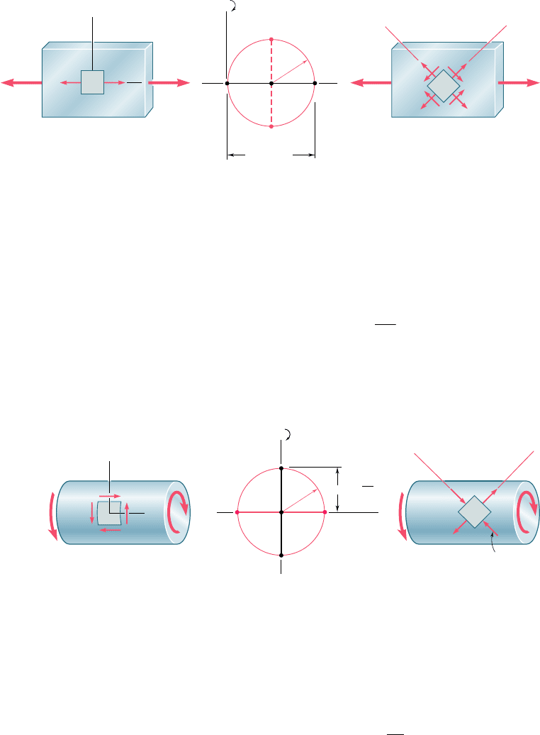
Mohr’s circle provides a convenient way of checking the results
obtained earlier for stresses under a centric axial loading (Sec. 1.12)
and under a torsional loading (Sec. 3.4). In the first case (Fig. 7.21a),
we have s
x
5 PyA, s
y
5 0, and t
xy
5 0. The corresponding points
X and Y define a circle of radius R 5 Py2A that passes through the
origin of coordinates (Fig. 7.21b). Points D and E yield the orienta-
tion of the planes of maximum shearing stress (Fig. 7.21c), as well
as the values of t
max
and of the corresponding normal stresses s9:
t
max
5 s¿ 5 R 5
P
2
A
(7.18)
In the case of torsion (Fig. 7.22a), we have s
x
5 s
y
5 0 and
t
xy
5 t
max
5 TcyJ. Points X and Y, therefore, are located on the t axis,
and Mohr’s circle is a circle of radius R 5 TcyJ centered at the origin
(Fig. 7.22b). Points A and B define the principal planes (Fig. 7.22c)
and the principal stresses:
s
max, min
56R 56
Tc
J
(7.19)
P'
x
P/A
D
E
C
Y
x
y
ed
X
R
x
(b)(a)(c)
PP'
'
max
P
Fig. 7.21 Mohr’s circle for centric axial loading.
T'
T
y
x
T'
T
b
a
Y
X
CBA
R
max
max
max
min
Tc
J
(a)(b)(c)
Fig. 7.22 Mohr’s circle for torsional loading.
bee80288_ch07_436-511.indd Page 456 10/30/10 1:39:08 AM user-f499bee80288_ch07_436-511.indd Page 456 10/30/10 1:39:08 AM user-f499 /Users/user-f499/Desktop/Temp Work/Don't Delete Job/MHDQ251:Beer:201/ch07/Users/user-f499/Desktop/Temp Work/Don't Delete Job/MHDQ251:Beer:201/ch07